Secure ACI Data Centers:
Deploying Highly Available
Services with Cisco and F5
Contents
Secure ACI Data Center: Deploying Highly Available Services with Cisco and F5 3
Next-‐Generation Data Center Fabric Architecture 3
Service Insertion Workflow in APIC 5
Solution Overview 7
Infrastructure Configuration 7
Bridge Domains 7
Transit Bridge Domain 8
Implementing Services with ASA and BIG-‐IP 10
Device Management Connectivity 11 Product Version Compatibility 11 Importing a Device Package 12
Procedure 13
Device Pre-‐Configuration 14
Pre-‐Configure ASA Device 14 Pre-‐Configure BIG-‐IP Device 15
Procedure 16
Device Installation 19
Procedure 19
ASAv HA Device Configuration 21
Procedure 21
BIG-‐IP LTM HA Device Configuration 25
Procedure 25
Service Graph Template Creation 28
Procedure 28
Verification 44
Subscribing Additional EPGs 44
Test Topology 46
Troubleshooting tips 47
Secure ACI Data Center: Deploying Highly Available
Services with Cisco and F5
Cisco and F5 have partnered to create a how-‐to guide describing the best practices for implementing highly available virtual services in the Cisco® Application Centric Infrastructure (Cisco ACI™) enhanced data center. This white paper focuses on how to implement a multiservice service graph (SG) between groups of endpoints. It focuses on the Cisco Adaptive Security Virtual Appliance (ASAv) and the F5 BIG-‐IP Local Traffic Manager (LTM) load balancer (LB) Virtual Appliance deployed on a VMware virtualized server farm connected to a Cisco ACI fabric of leaf and spine switches.
Next-‐Generation Data Center Fabric Architecture
The ACI framework revolutionizes the traditional data center model by separating logical and physical network topologies and enabling centralized control, automation, and service orchestration. The next-‐ generation data center fabric becomes an ultra-‐high-‐speed network that can dynamically configure and interconnect heterogeneous devices based on application policy needs. The Application Policy
Infrastructure Controller (APIC) represents a single point of orchestration, policy provisioning, and network intelligence. Cisco ACI is designed to translate application requirements into services required for
successfully deploying applications in a simplified and automated fashion. The two key network elements for this white paper are as follows:
• Endpoint groups (EPGs) define similar service consumers in terms of application services and
usage. For instance, all web servers on the same network segment may be grouped into a single EPG. Each leaf port can belong to any number of EPGs. Networks that are external to the fabric are represented as EPGs as well. The fabric controls communication between different EPGs according to a configured policy set, and the default behavior is to block all other traffic.
• Service graphs (SGs) or service chains are ordered processing sequences of inter-‐EPG traffic
through service nodes based on the established contracts. For each allowed flow in a contract, the associated SG defines the packet path through the network. For instance, the administrator may have all HTTPS traffic on TCP port 443 traverse a stateful firewall, then a load balancer, and finally a network analysis device. SGs allow for a greater level of abstraction and reuse, which also supports policy simplification.
Figure 1 illustrates a fabric view of the network and its physical and virtual devices. Any device attaches to the fabric at any available port at any physical location. The desired topology is created completely by the
348072
Figure 1. Fabric Network View and Device Attachment
Service Customers
More information on how the new ACI model abstracts other network elements can be found at the following URLs:
• Cisco ACI—
http://www.cisco.com/c/en/us/solutions/data-‐center-‐virtualization/application-‐centric-‐ infrastructure/index.html
• Cisco APIC—
http://www.cisco.com/c/en/us/products/cloud-‐systems-‐management/application-‐policy-‐infrastructu re-‐controller-‐apic/index.html
• F5 Synthesis products on ACI—https://devcentral.f5.com/cisco/getting-‐started
This white paper assumes that readers have a basic understanding of ACI terminology and functionality, and will read the referenced documents, thus reducing the need for this document to duplicate design, configuration steps, and concepts.
ACI Fabric
Spine Nodes
Leaf Nodes
Virtual
Leaf
Service Insertion Workflow in APIC
Figure 2 shows a logical workflow composed of five basic steps needed to add a service and graph it into EPG communication paths. Upon completion, this workflow creates a tenant and renders an SG in the fabric. Devices are set up to allow registration, so the APIC can then orchestrate the device data plane for a given tenant.
Figure 2. Service Insertion Workflow
To address the workload, a tenant can define additional service devices and consume those into new SGs. Further, any SG can easily be upgraded or downgraded to leverage any registered ASA devices of different performance levels. In this paper, only a single high-‐availability (HA) device pair was created for each service type within the tenant.
The five general steps in creating a tenant with ASA services are as follows:
1. Create the tenant – Creation of the tenant along with its application profiles, EPGs, bridge
domains (BDs), and contracts is the basis needed before any L4–L7 services can be added. Refer to APIC documentation for more details on this step.
2. Define the L4–L7 service device clusters – Allow for virtual (VMM) or physical domain clusters of devices. Register them to the APIC.
3. Create the SG – Device-‐specific policies are created and ready for provisioning to any registered devices (for example, security policy, LB listener, ports/protocols, and so on).
Create Tenant Service Device Add L4–L7
Cluster
Create Service Graph
Logical Device Context
Apply Graph to Contract
348073
• Contract
• Bridge domains
• EPGs
• Define logical
cluster for each device
• Register ASAs
and F5 to respective devices
• High availability
• Supports both
physical and virtual
• Define device
configuration
• Data plane
• Security policy
• LB pool
• Listener address
• Device-specific
features
• Connectors to
bridge domains
• Clusters to SGs
• Render in fabric
• Orchestrate
device data plane
• Verify deployed
For more information on ACI service insertion, refer to Service Insertion with Cisco Application Centric Infrastructure, available at the following URL: http://www.cisco.com/c/en/us/solutions/collateral/data-‐ center-‐virtualization/application-‐centric-‐infrastructure/white-‐paper-‐c11-‐732493.html
Solution Overview
Following the service insertion workflow, the topology shown in Figure 3 was created to illustrate the benefits of a highly available ACI design using the Cisco ASAv firewall and the F5 BIG-‐IP virtual load balancer.
Figure 3. Simplified Topology of EPGs, Contracts, and Devices
This diagram is not meant to illustrate all possible architectures but rather to communicate a typical architecture, showing where the devices fit into a Cisco ACI architecture.
Infrastructure Configuration
The following sections describe the topology configurations implemented before services deployment.
Bridge Domains
Bridge domains are a fundamental element of the ACI infrastructure and have specific capabilities and features critical to the successful deployment of services within the fabric. In the test topology, each of the EPGs, networks, and bridge domains are deployed using the standard settings following the ACI design guide.
Table 1. Bridge Domains, EPGs, and Subnets
Note Additional EPGs were configured for testing purposes, but not listed here.
The L3 outside external routed connection was implemented following the Connecting Application Centric Infrastructure (ACI) to Outside Layer 2 and 3 Networks white paper. More information can be found at the following URL:
http://www.cisco.com/c/en/us/solutions/collateral/data-‐center-‐virtualization/application-‐centric-‐ infrastructure/white-‐paper-‐c07-‐732033.html
Transit Bridge Domain
The firewall must be deployed between two separate BDs. This is true even for transparent firewall mode where the subnet can be added only in a single BD. A second BD must be created with no subnet assigned to it.
Note A transparent ASA firewall cannot be deployed between two EPGs in the same BD; the ASA
will not know which interface contains the source and destination devices. Each ASA interface must be in a different BD.
Endpoint Group Bridge Domain Subnet
CDE-WS (web servers) Francisco-Net1-BD21 10.11.21.0/24 CDE-DB (web database) Francisco-Net1-BD21 10.11.21.0/24 ASA_Out (ASA external interface Francisco-Net1-BD22 10.11.22.0/24 L3-Outside (External Routed L3 network) 0.0.0.0/0
HA-ASA-FO Francisco-Net1-BD-HA-L2 None
HA-ASA-State Francisco-Net1-BD-HA-L2 None
HA-F5-FOState Francisco-Net1-BD-HA-L2 None
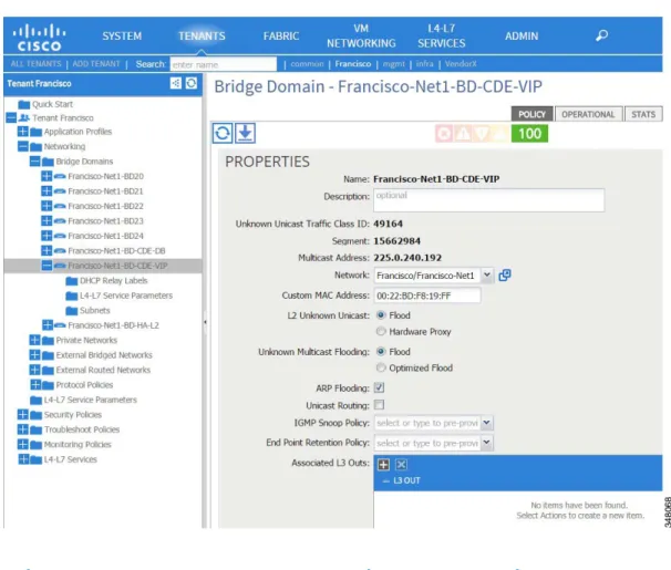
For a multiservices SG, this will be an intermediary BD for the internal interface of the firewall and external interface of the LB. To facilitate proper discovery and communications, specify the following properties for this BD, adjust these settings (see Figure 4):
• Network: the private network containing the EPGs • L2 Unknown Unicast: Flood
• ARP Flooding: enabled • Unicast Routing: disabled
When finished, click Submit to save these settings.
Figure 4. Bridge Domain Configuration
Implementing Services with ASA and BIG-‐IP
The following sections show how to deploy a multiservices SG using the Cisco ASAv firewall and F5 LTM virtual load balancer to a tenant’s L4–L7 services. The vendor-‐specific device packages import features into APIC and display configurations through the GUI or API. Devices are created and then deployed using an SG.
The ASA integrates into ACI as a service producer in the following modes:
• Go-‐To – The routed firewall maintains static and dynamic routing and ARP tables.
• Go-‐Through – The transparent firewall bridges VLANs and tracks MAC address tables.
These two modes are selected in the APIC when the device is added, and must match the configured ASA firewall mode.
Additional information about deploying ASAs in the ACI fabric can be found in the guide
Integrating the Cisco ASA with Cisco Nexus 9000 Series Switches and the Cisco Application Centric Infrastructure at the following URL:
http://www.cisco.com/c/en/us/solutions/collateral/data-‐center-‐virtualization/application-‐centric-‐
The F5 BIG-‐IP integrates into the ACI fabric as a service producer in the following modes:
• Single context • Multi-‐context
More information about F5 and devices ready for the ACI fabric can be found in the F5 APIC Users’ Guide at the following URL:
https://downloads.f5.com/esd/serveDownload.jsp?path=/third-‐party-‐ integration/ciscoapic/1.1.1/english/build-‐161/&sw=Third-‐Party-‐
Integration&pro=CiscoAPIC&ver=1.1.1&container=Build-‐161&file=cis co-‐apic-‐users-‐guide-‐build-‐161a.pdf
Device Management Connectivity
Each device is managed via a separate management interface. The management port of the system is connected to out-‐of-‐band switches outside of the ACI architecture (not shown in diagrams) providing management-‐only access.
Product Version Compatibility
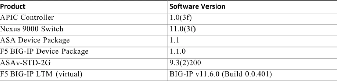
The following sections of this solution guide are based on the versions specified in Table 2. As the Cisco ACI solution evolves, the APIC GUI will change, prompting relevant changes in device package support and updates to the various solution guides.
Table 2. Cisco ACI with ASA and F5 Solution Product Versions
Product Software Version
APIC Controller 1.0(3f)
Nexus 9000 Switch 11.0(3f)
ASA Device Package 1.1
F5 BIG-IP Device Package 1.1.0
ASAv-STD-2G 9.3(2)200
F5 BIG-IP LTM (virtual) BIG-IP v11.6.0 (Build 0.0.401)
Importing a Device Package
For APIC to understand a device’s capabilities, a device package must be imported. Multiple versions of the package can be installed in APIC.
The ASA APIC package is available on the Cisco website:
https://software.cisco.com/download/type.html?mdfid=286119613&flowid=50242
The F5 Device Package for Cisco APIC is available as a free download via http://downloads.f5.com
Procedure
Step 1 Navigate to L4–L7 SERVICES / PACKAGES.
Step 2 Right-‐click on L4–L7 Service Device Types to import the device package (see Figure
5.)
Figure 5. L4–L7 Service Device Types
Step 3 Import and review the latest device package previously downloaded to your PC. The
example in Figure 6 shows the ASA device package downloaded from Cisco.com. The BIG-‐IP device package will also need to be downloaded and imported from F5.com.
Figure 6. Import Device Package
Device installation and configuration can now be performed in the APIC, exposing the features supported by the imported version of the device package.
Device Pre-‐Configuration
Before a device can be added to the APIC, it requires some basic configurations to enable secure network connectivity and authentication credentials to its management interface. The following sections show the necessary configurations for the ASAv and BIG-‐IP devices.
Pre-‐Configure ASA Device
Before applying the initial configurations, the ASA device should be placed in the appropriate firewall mode; transparent for Go-‐Through or routed for Go-‐To, so the mode matches the option under the APIC device policy.
!For Go-To mode (ASA comes up in Routed mode be default) no firewall transparent !For Go-Through mode (used in this solution) firewall transparent
Note Changing firewall modes erases the ASA configuration. The proper mode should be selected
before additional configurations are entered in the device.
The following ASA preconfiguration allows the APIC to communicate with and register the ASA device under L4–L7 services. The ASA M0/0 interface is connected to a separate switch outside of the fabric, and is reachable by the APIC.
!Management interface (OOB) interface Management0/0
management-only nameif management security-level 0
ip address 10.11.241.151 255.255.255.0 !Credentials for ssl session
aaa authentication http console LOCAL http server enable
http 10.11.236.0 255.255.255.0 management
username apic password <device_password> privilege 15
!ROUTES needed to reach APIC’s
route management 10.11.236.131 255.255.255.255 10.11.241.1 1 route management 10.11.236.132 255.255.255.255 10.11.241.1 1 route management 10.11.236.133 255.255.255.255 10.11.241.1 1 !Ensure Crypto key is
present on ASA ASAv-1# show crypto key
PST Mar 6 2015 Key name: <Default-RSA-Key>
Usage: General Purpose Key !Ensure the device is
properly licensed ASAv-1# show license all
Cisco Smart Licensing Agent, Version 1.1.4_throttle/13 Smart Licensing Enabled: Yes
UDI: PID:ASAv,S N:XXXXXXXX XX
Compliance Status: In Compliance
Pre-‐Configure BIG-‐IP Device
The BIG-‐IP virtual edition is installed by following the BIG-‐IP Virtual Edition Setup Guide for VMware ESXi. For more information, see the following URL:
https://support.f5.com/kb/en-‐us/products/big-‐ip_ltm/manuals/product/ve-‐vmware-‐esx-‐esxi-‐11-‐3-‐ 0.html
After deploying the BIG-‐IP virtual appliance, initial configurations are performed first via the console CLI and then in the device web interface.
All of the prerequisites and detailed steps for installing the BIG-‐IP can be found in the BIG-‐ IP_Virtual_Edition_Setup_Guide_for_VMware_ESXi at the following URL:
https://support.f5.com/content/kb/en-‐us/products/big-‐ip_ltm/manuals/product/ve-‐vmware-‐esx-‐esxi-‐ 11-‐ 3-‐0/_jcr_content/pdfAttach/download/file.res/BIG-‐
IP_Virtual_Edition_Setup_Guide_for_VMware_ES_Xi.pdf
Procedure
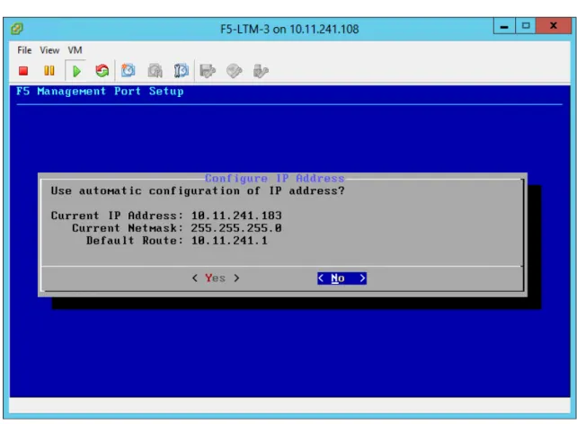
Step 1 To assign the management IP address and initial settings, log into the device from the
vSphere console interface (username: root / password: default) and execute the config command.
Step 2 Enter the management IP address, netmask, and default route, as shown in Figure 7.
Figure 7. F5 Management Port Setup
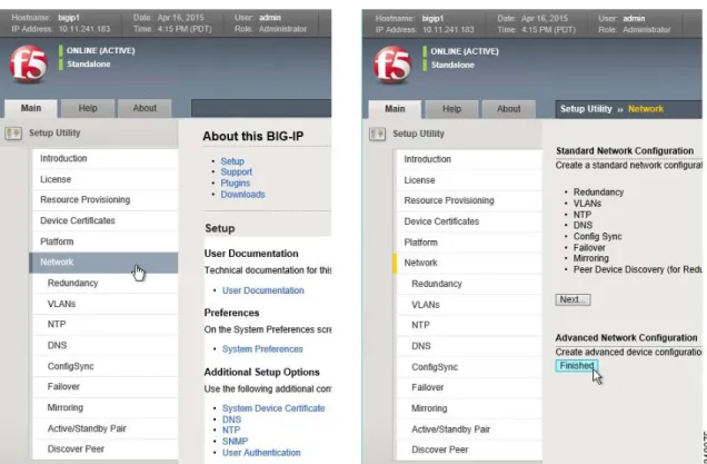
Step 3 Next, open the web interface by connecting to the device’s management IP address
https://<ip address>/ and log in with the default credentials (admin / default).
Step 4 Under the Setup Utility menu, click Network and then Finished, as shown in Figure 8.
Figure 8. F5 Setup Utility Menu
Step 5 Once the configuration is saved, select System from the main menu, then License.
Step 6 If the device is not already licensed, follow the steps in the installation guide to obtain
and install the proper device license.
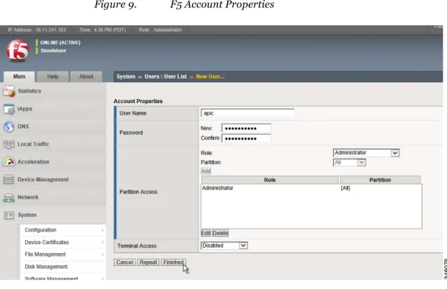
Cisco recommends adding a unique user account to be used by the APIC (best practice security is to never use default system accounts; they should be disabled and removed).
Step 7 Under the Main menu, select System and Users.
Step 8 Click the Create button in the upper right corner. Add the APIC username, set a complex
password, and specify the proper partition access (see Figure 9).
Figure 9. F5 Account Properties
Step 9 Click Finished.
This completes the pre-‐configuration steps necessary to deploy the F5 BIG-‐IP device.
Device Installation
After the initial device pre-‐configurations have been completed, they can now be added to the APIC.
Procedure
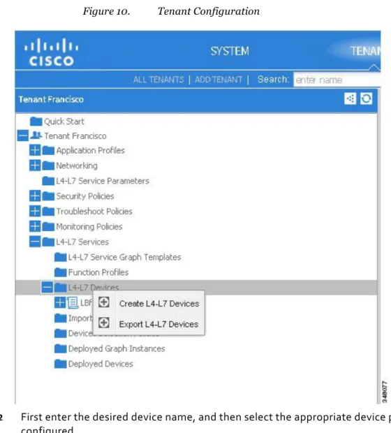
Step 1 From the APIC GUI, navigate to the appropriate tenant where the device is to be added
and select Create L4–L7 Devices from the popup menu (see Figure 10).
Each device package will require different information to be entered. The figures in the next section show the configuration of HA pairs for both the ASAv and F5 BIG-‐IP LTM LB.
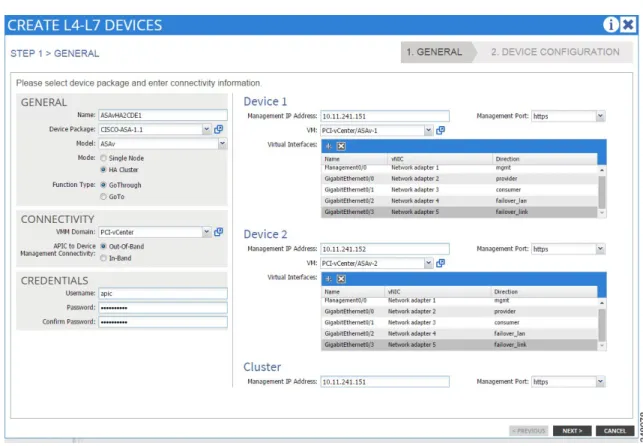
ASAv HA Device Configuration
Figure 11 shows the Create L4–L7 Devices configuration page.Figure 11. Create L4–L7 Devices—Step 1
Procedure
Step 1 The network adapters used for failover_lan and failover_link are connected to switched
network segments that span the pool of hypervisors. This can be implemented by creating EPGs and BDs, then associating them with an appropriate vSphere VMM domain. This will populate the port groups to vSphere where they can be assigned to the specified device vNIC adapters. (See Figure 12.)
Figure 12. Network Adapter Configuration
Step 2 Configure the failover interfaces and specify the standby IP addresses for the
management interfaces.
Step 3 To add the second failover interface for the state link, click the plus sign in the left column
of the parameters list next to the Failover Interface Configuration line. (See Figure 13.) Figure 13. Create L4–L7 Devices—Step 2
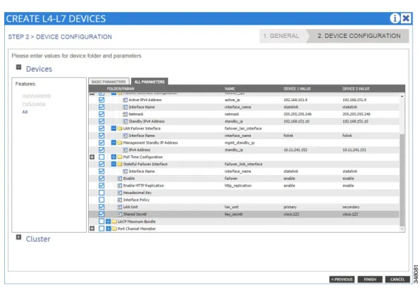
Step 4 Enable Failover and HTTP Replication, specify the secret key to encrypt communication, and
designate which unit is primary and secondary. (See Figure 14.)
Figure 14. Create L4–L7 Devices—Parameters
Step 5 After configuring the devices, click the Cluster option in the bottom left to add global
configurations used for the general device configuration (see Figure 15). These items include DNS Servers, Logging, and NTP settings. Be sure to specify the interfaces used for
communication and that appropriate routes in the device exist to support proper communications.
Figure 15. Global Configurations
Step 6 If the device configuration is complete and error-‐free, the installation completes and the
state shows stable. (See Figure 16.)
BIG-‐IP LTM HA Device Configuration
Procedure
Step 1 Assign the device name and select the package for the F5. When selecting the model, Manual
is the recommended setting.
Only the two data interfaces need to be configured, not the Failover state interface. You must use the format shown in Figure 17 for the interface names (1_1 and 1_2) and assign them to adapters 2 and 3. Network adapter 1 is used for out-‐of-‐band management of the device.
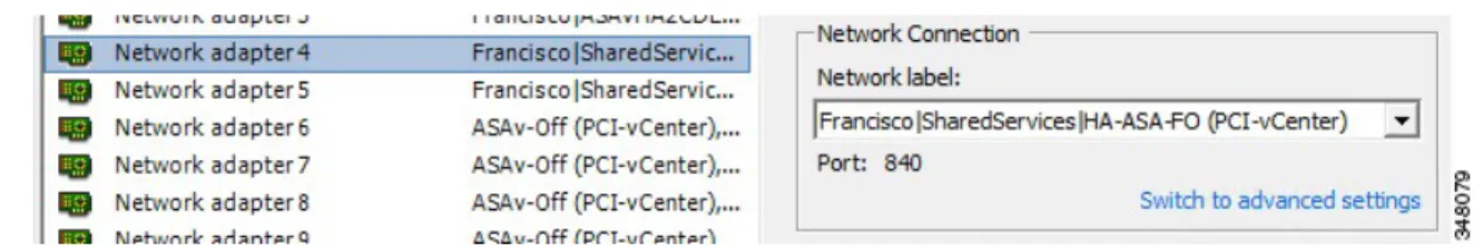
Step 2 Similar to the ASA device deployment, network adapter 4 is used for failover and must be
connected to a switched network segment that spans the pool of hypervisors. This can be implemented by creating an EPG and bridge domain, then associating it with an appropriate vSphere VMM Domain. This will populate the port group to vSphere where it can be assigned to the specified device virtual network interface card (vNIC) adapter. (See Figure 18.)
Step 3 On the next screen, the common device configurations such as DNS, Hostname, NTP, and
syslog servers are specified. (See Figure 19.) The failover interface must be identified as 1_3, and each device in the HA pair must be assigned a VLAN, IP address, and network mask.
Figure 19. BIG-IP LTM Configuration—Step 2
Step 4 After the device has been implemented, the configuration state will show stable if there are
Figure 20. Configuration Complete
Step 5 In the web interface of the F5 LB, the devices will show Online, Active, or Standby and
whether they are In Sync with each other in the top left corner. (See Figure 21.) Figure 21. F5 Load Balancer Web Interface
Service Graph Template Creation
Procedure
Step 1 Once the devices have been added to the APIC, and the device states are stable, the next
step is to create the SG template. (See Figure 22.) Figure 22. SG Template—Step 1
Step 2 Assign the SG template a descriptive name that will represent the functionality of the
services it can provide. In this solution, the two nodes will be deployed together with the firewall in transparent mode and the BIG-‐IP in two-‐arm mode. (See Figure 23 and Figure 24.)
Figure 23. SG Template Information (1)
Step 4 Once the SG is created, the next step is to apply the SG. This allows for selection of the
devices and EPGs that the SG will be deployed to via a contract. (See Figure 25.) Figure 25. Applying the SG
Overall, the SG will be initially deployed between the EPG containing the web servers and an EPG that contains the external bridge domain subnet of the ASA device.
Step 5 Define a new contract and filter the protocols matching the policy to be deployed in the ASA.
Click Next to proceed to the next step.
Figure 26. Apply L4–L7 SG Template to EPGs
Step 6 Select the L4–L7 ASA HA pair device created earlier.
for the traffic flow between the two devices. This will be the internal interface of the ASA and has specific settings defined earlier in this guide. A firewall must be deployed between two different bridge domains.
The ASA device package implements two access control entries by default, HTTP and HTTPS. None of the filters defined in the contract for the service graph are carried over into the access policy. By clicking the plus sign in the left parameters column, additional entries can be added. In this example, ICMP was added, and HTTP was changed to SSH.
Note At the time of this testing, the ASA package improperly numbered the order of the access
control entries. Each order number should be unique (for example, 10, 20, 30) but both default HTTP and HTTPS entries have 10 as the order number. You must change one or you will get an error when deploying the service graph.
Step 7 Configure the IP address and subnet mask of the bridge group interface. (See Figure 27.)
Figure 27. Step 2—Firewall
Step 8 Further down in the firewall configuration the access policy is applied to the interfaces (see
Figure 28).
The device package applies the access-‐list-‐inbound only to the internal interface as the default. For expected functionality, also apply the access-‐list-‐inbound to the external interface to allow permitted communications. More complex access policies can be defined and implemented separately for internal and external interfaces, but such configuration was beyond the scope of this paper.
Figure 28. Access Policy Applied to Interfaces
Step 9 Configure the device default route under the external interface by expanding the static routes
list and specifying the network, netmask, and gateway used for the bridge-‐group BD subnet. (See Figure 29.)
Step 10 Before completing the deployment of the SG, it is a best practice to disconnect the data
interfaces of the ASAv to prevent network loops during deployment. This is performed in the vSphere console. (See Figure 30.)
Figure 30. Disconnecting the Data Interfaces of the ASAv
The next step is the configuration of the LB.
Step 12 Enter the following features and parameters on the ALL PARAMETERS tab:
Device Config > LocalTraffic > Monitor Monitor Frequency = 5
Monitor Send String = GET \r\n Monitor Protocol = HTTPS
Number of Monitor Failures to Trigger = 3 Pool > Pool Monitor
Select Pool Monitor = LocalTraffic/Monitor
Load Balancing Method = ROUND_ROBIN (Select:C1) Network > External SelfIP
Enable Floating = NO
External Self IP = 10.11.22.183 Self IP Netmask = 255.255.255.0 Internal SelfIP
Enable Floating? = NO
Internal Self IP Address = 10.11.21.183 Internal Self Netmask = 255.255.255.0 Route
Destination IP Address = 0.0.0.0 Destination Netmask = 0.0.0.0
Next Hop Router IP Address = 10.11.22.1 Function Config > Listener
Protocol = TCP
Virtual Server IP Address = 10.11.22.101 Virtual Server Netmask = 255.255.255.255 Virtual Server Destination Port = 443 Network Relationship
Select Network = Network Pool
EPG Connect Rate Limit = 2000 EPG Connection Limit = 2000 EPG Destination Port = 443 EPG Ratio = 1
Figure 31 shows the various sections of the ALL PARAMETERS tab. Figure 31. ALL PARAMETERS Tab (1)
Step 13 After completing configuration of the LB, click FINISH.
Step 14 Deploying the SG completes the data plane configuration needed for the firewall and LB.
The above parameters defined in APIC translate to the following excerpts of ASA configuration:
interface GigabitEthernet0/0 nameif internalIf bridge-group 1 security-level 100 ! interface GigabitEthernet0/1 nameif externalIf bridge-group 1 security-level 50 ! interface GigabitEthernet0/2 description LAN Failover Interface
!
interface GigabitEthernet0/3 description STATE Failover Interface
!
interface Management0/0 management-only
nameif management security-level 0
ip address 10.11.241.151 255.255.255.0 standby 10.11.241.152 !
interface BVI1
ip address 10.11.22.251 255.255.255.0 ! dns server-group DefaultDNS name-server 10.11.230.100 name-server 10.11.230.101 domain-name cisco-x.com !
access-list access-list-inbound extended permit tcp any any eq ssh access-list access-list-inbound extended permit tcp any any eq https access-list access-list-inbound extended permit icmp any any
!
logging enable
logging buffer-size 100000 logging buffered
informational
logging host management 10.11.230.161 !
failover
failover lan unit primary failover lan interface folink
GigabitEthernet0/2 failover key ***** failover replication http
failover link statelink GigabitEthernet0/3
failover interface ip folink 192.168.151.1 255.255.255.248 standby 192.168.151.2
failover interface ip statelink 192.168.151.9 255.255.255.248 standby 192.168.151.10
!
access-group access-list-inbound in interface internalIf access-group access-list-inbound in interface externalIf
!
route externalIf 0.0.0.0 0.0.0.0 10.11.22.1 1 !
ntp server 10.11.255.2 source management
ntp server 10.11.255.1 source management prefer
The above parameters defined in APIC translate to the following excerpts of BIGIP configuration:
sys global-settings { gui-setup disabled
hostname F5v-LTM-1.cisco-x.com mgmt-dhcp disabled } sys management-ip 10.11.241.181/24 { description configured-statically }
sys dns {
name-servers { 10.11.230.101 } }
sys ntp {
servers { 10.11.255.1 } sys sshd { }
sys state-mirroring { addr 192.168.181.1
}
sys syslog {
net route-domain /apic_4223/apic_422 3 { id 3149
vlans { /apic_4223/apic_4223_16401 /apic_4223/apic_4223_32785 } } net self /apic_4223/apic_4223_Inter nalSelfIP { address 10.11.21.181%3149/24 traffic-group /Common/traffic-group-local-only vlan /apic_4223/apic_4223_32785 } net self /apic_4223/apic_4223_Exter nalSelfIP { address 10.11.22.181%3149/24
traffic-group /Common/traffic-group-local-only vlan
/apic_4223/apic_4223_16401 }
net vlan /apic_4223/apic_4223_32785 { interfaces {
1.1 { } }
tag 109 }
net vlan /apic_4223/apic_4223_16401 { interfaces {
1.2 { } }
tag 184 }
net fdb vlan
/apic_4223/apic_4223_32785 { } net fdb vlan
/apic_4223/apic_4223_16401 { }
ltm node
/apic_4223/10.11.21 .101%3149 { address 10.11.21.101%3149 }
ltm node /apic_4223/10.11.21.102%3149 {
address 10.11.21.102%3149 } ltm node /apic_4223/10.11.2 2.201%3149 { address 10.11.22.201%3149
}
ltm pool
/apic_4223/apic_42 23_Pool { members { /apic_4223/10.11.21.10 1%3149:443 { address 10.11.21.101%3149 connection-limit 2000 rate-limit 2000 } /apic_4223/10.11.21.10 2%3149:443 { address 10.11.21.102%3149 connection-limit 2000 rate-limit 2000 } } monitor /apic_4223/apic_4223_Monitor } ltm virtual /apic_4223/apic_4223_4726_ ADC { destination
/apic_4223/10.11.22.101%31 49:443 ip-protocol tcp mask 255.255.255.255 mirror enabled pool
/apic_4223/apic_42 23_Pool profiles {
/Common/tcp { } }
source 0.0.0.0%3149/0 source-address-translation
{ type automap }
translate-address enabled translate-port enabled vlans {
/apic_4223/apic_4223_16401 } vlans-enabled } ltm virtual-address /apic_4223/10.11.22.101%3149 { address 10.11.22.101%3149 arp enabled
compatibility enabled
defaults-from /Common/https destination *:*
interval 5 ip-dscp 0
send "GET /\\r\\n" time-until-up 0 timeout 16
}
net route /apic_4223/apic_Route { gw 10.11.22.1%3149 network default%3149
Once the devices have been deployed, the external interface of the ASA device must be assigned to the appropriate bridge domain.
Step 15 Expand the firewall device under the Device Selection Policies for the tenant and select the BD
associated with the subnet used by the BVI IP address, then click Submit. (See Figure 32.) Figure 32. Selecting the BD—BVI IP Address
Step 16 Expand the LB device under the Device Selection Policies for the tenant and select the
BD associated with the subnet used by the internal IP address, then click Submit. (See Figure 33.)
Figure 33. Selecting the BD—Internal IP Address
Step 17 Expand the new SG that was created and deployed under the template and enable
Attachment Notification for each of the interfaces of the firewall and LB devices, clicking Submit for each. (See Figure 34.)
Step 18 Open the vSphere console and edit the settings for both of the ASAv devices, verify the
proper BDs have been automatically assigned to internal and external interfaces by the APIC, and then enable the interfaces by checking the Connected boxes. Click OK to save the settings. (See Figure 35.)
Figure 35. ASAv Virtual Machine Properties
Verification
A client system in the ASA_Out EPG can now open a browser and connect to the Listener VIP address and access resources from the pool of servers. (See Figure 36.)
Figure 36. Client1
Subscribing Additional EPGs
To enable other EPGs to use this same SG and access the Listener VIP address, add them as consumers of the ASA and LB_CDE contract. (See Figure 37.)
Clients from those EPGs (including the external EPG that represents systems outside of the ACI fabric) can also connect to the VIP address and the underlying pool of servers. (See Figure 38 and Figure 39.)
Figure 38. Client 2
Figure 39. External Client
In summary, highly available virtual services can be created, deployed, and managed via the ACI APIC controller, revolutionizing the traditional data center model with a single point of orchestration, policy provisioning, and network intelligence.
Test Topology
Figure 40 and Figure 41 represent the detailed topology used for testing. Figure 40. Hardware Connectivity
Figure 41. Logical APIC Configuration
Troubleshooting Tips
When installing and deploying the service devices, it is helpful to monitor the debug logs on the APIC for any errors that may occur. To monitor these logs, open an SSH terminal session to the APIC and use the following command to tail the appropriate log you wish to view:
tail -f /data/devicescript/F5.BIGIP.1.1.0/logs/debug.log tail -f /data/devicescript/CISCO.ASA.1.1/logs/debug.log
Several SSH sessions tailing multiple logs can be opened simultaneously. In a multiple APIC design (normally three), this log process may be active on any one of the APICs. Open a session to each APIC. When you identify the active logging APIC, you can then close the other session windows.