SmartNode™ Model 1200, 1400 & 4552
VoIP Gateway Routers
Quick Start Guide
Document Number: 13211U7-001 Rev. A Part Number: 07MSWGUI-QS
Revised: October 31, 2005
Sales Office: +1 (301) 975-1000 Technical Support: +1 (301) 975-1007 E-mail: [email protected]
1.0 Power up the SmartNode
1. Connect the SmartNode to a power source using the included power supply and cable.
2. When the Power LED stops blinking and remains lit, the SmartNode is ready to configure.
2.0 Set your PC to DHCP
• The SmartNode contains no user serviceable parts. The equipment shall be returned to Patton Electronics for repairs, or repaired by qualified service personnel.
• Mains Voltage: Do not open the case when the power cord is con-nected. For systems without a power switch, line voltages are present within the power supply when the power cord is connected. The mains outlet that is utilized to power the SmartNode router shall be within 10 feet (3 meters) of the device, shall be easily accessible, and protected by a circuit breaker
• The smartNode is not shipped with power cables. For AC powered units, ensure that the power cable used meets all applicable stan-dards for the country in which it is to be installed, and that it is con-nected to a wall outlet which has earth ground.
• Hazardous network voltages are present in WAN ports regardless of whether power to the SmartNode is ON or OFF. To avoid electric shock, use caution when near WAN ports. when detaching the cables, detach the end away from the SmartNode first.
• Do not work on the system or connect or disconnect cables during periods of lightning activity.
The interconnecting cables shall be acceptable for external use and shall be rated for the proper application with respect to voltage, current, anticipated temperature, flam-mability, and mechanical serviceability.
The interconnecting cables shall be acceptable for external use and shall be rated for the proper application with respect to voltage, current, anticipated temperature, flam-mability, and mechanical serviceability.
WARNING
CAUTION
This guide will allow you to quickly access the configuration interface of a SmartNode and give an overview of the different elements you can or need to configure. For detailed information on all configuration parameters refer to the SmartWare software configuration guide.
The SmartNode has a built in DHCP Server which allows an automatic IP connection with a connected PC. To pre-pare the connection you need to configure the PC to use DHCP. The following paragraphs show how to do this on Windows. For other operating systems refer to the operating instructions of the PC.
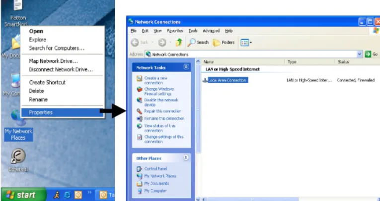
1. Right-click on My Network Places and select Properties in the context menu (see figure 1).
Figure 1. Displaying the Network Connections window
2. Double-click on Local Area Connection and click on Properties to open the Internet Protocol (TCP/IP) Properties window (see figure 2).
3. Select Obtain an IP address automatically and Obtain DNS server address automatically options.
4. Click OK to save changes and close the properties windows.
3.0 Connect the PC to the SmartNode LAN Port
Now use the included Ethernet cable to connect the configured PC to the SmartNode. The factory default config-uration of the SmartNode defines Ethernet port 0/1 as the LAN port.Note Most SmartNode Ethernet ports are Auto-MDIX which means that you can use a standard straight-wired Ethernet cable to connect to the PC or a hub/switch.
Figure 3. Connecting the SmartNode to the network
Note As an alternative, you can connect to the console port (available on most models). Refer to the appro-priate “Getting Started Guide” for detailed instructions on how to access the command line interface (CLI) through the console port.
3.1 Open the Configuration Interface
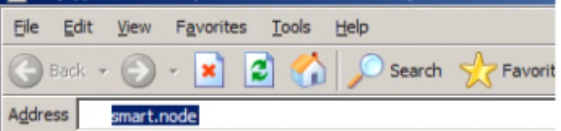
1. Once IP connectivity is established, use a web browser to get access to the SmartNode configuration inter-face. Enter “smart.node” in the address bar to get started (see figure 4).
Figure 4. Using a web browser to access the SmartNode configuration interface
Model Connect to port
SN1200/1400 ETH 0/1, use crossover cable or hub SN4552 ETH 0/1 any one of the 4 ports, Auto-MDIX
LAN (ETH 0/1) Network interface PC LAN Internet or WAN (optional) WAN (ETH 0/0)
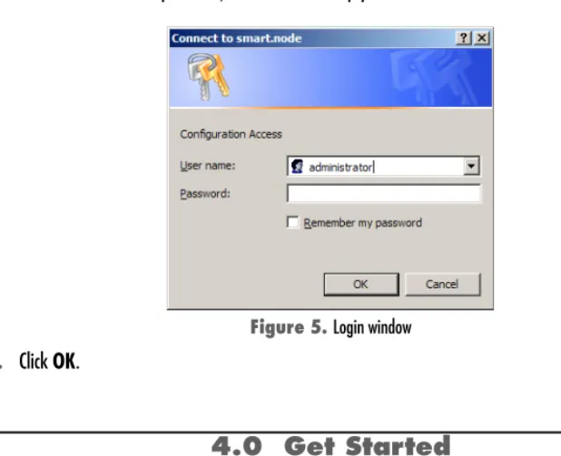
2. The subsequent pop-up window asks you for the login credentials (see figure 5). The factory default login credentials are:
User Name: administrator
Password: There is no password, leave this field empty
Figure 5. Login window 3. Click OK.
4.0 Get Started
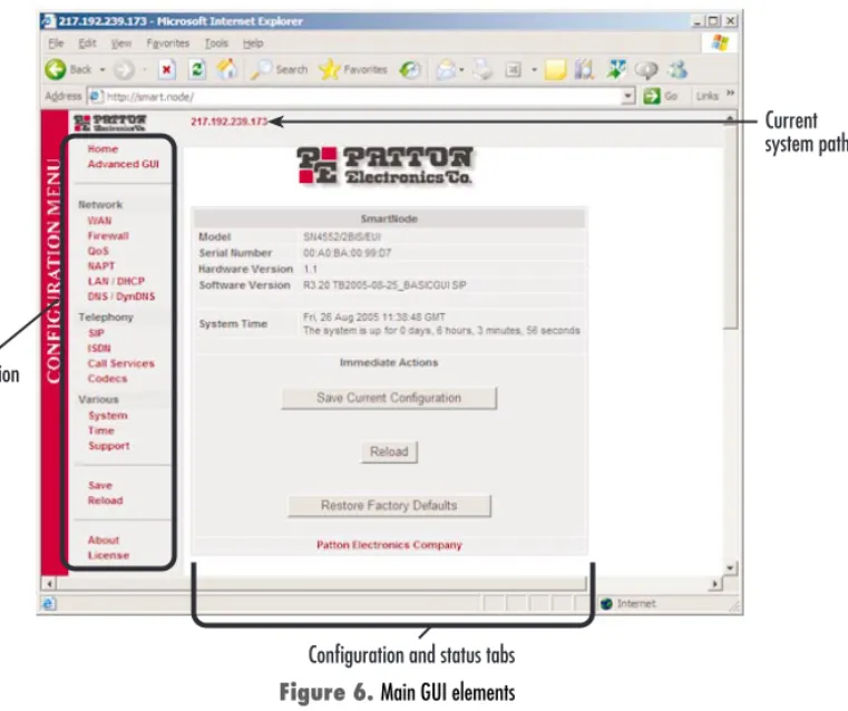
After successful login you get to the SmartNode home page, and you can configure your device. You will be pre-sented the following home page, which contains buttons to store the current configuration state, reload the device and restore to factory defaults. The home page also shows some system information. You can always go back to the home page by clicking Home in the navigation bar.
The GUI consists of the following main elements (see figure 6):
• The “Navigation Bar” on the left edge presents you with a menu listing giving access to the various
configura-tion and status pages of the SmartNode.
• At the top of the page you see the “Current System Path” which displays the location and element currently presented in the main area.
• The rest of the page displays the configuration and status information for the different features of
the SmartNode.
Figure 6. Main GUI elements
During the whole configuration process, all your changes are only applied—that is, saved in volatile memory (RAM). To store the settings in non-volatile memory (i.e. make them survive power failure or manual reload), return to the home page and press the Save Current Configuration button.
Navigation bar
Configuration and status tabs
Current system path
5.0 Access the Internet
Connect an Ethernet cable from the WAN port on the SmartNode to the upstream WAN Internet connection. Begin the configuration for Internet access with the WAN page.
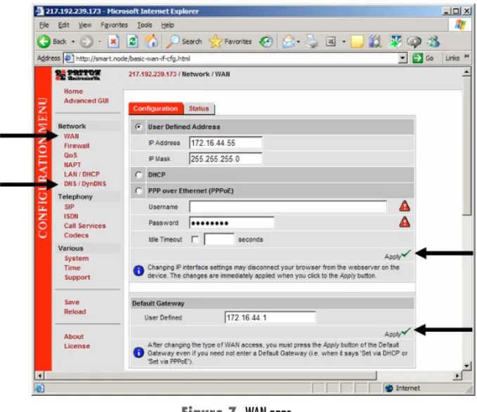
Figure 7. WAN page 5.1 Connecting a PC and logging in
Here are some special hints you may use when configuring your SmartNode:
There are three different configuration options for the WAN Internet connection (see figure 7):
• DHCP (client—factory default). The SmartNode’s WAN port has a DHCP client enabled that uses an
estab-lished Internet connection to get the Internet connectivity parameters (IP address, default gateway) automatically For each box containing an “Apply” button, fill in the required fields and press “apply” once. The settings are applied immediately after the button is pressed. If there are several boxes with an “Apply” button on one page, fill in the information per box and press the button for each box separately. This saves the new config-uration parameters in volatile memory (RAM) only.
The “alert” symbol shows you that somewhere a user input is missing for correct functionality. In the case of the present WAN page, you can ignore them, because the respective title bullet (“PPP over Ethernet”) is not selected.
The “info” symbol denotes hints to ease configuration or to avoid pitfalls. Read them whenever you encounter them!
from a DHCP server. Use this option when connecting the SmartNode to a DSL router, a cable modem, or to a company LAN (with a DHCP server). This is the factory default configuration so no configuration is required, only the LAN and WAN Ethernet connections should be made to access the Internet immediately.
• PPPoE. The SmartNode establishes the connection with the Internet using PPPoE. This is most commonly
used when the SmartNode is connected to a DSL bridge, or a DSL router that is configured in bridge mode (most routers are capable of this).
Enter the DSL credentials (username and password) on the SmartNode and click on the Apply button.
• User Defined Address. The SmartNode uses an existing internet connection which does not provide an
upstream DHCP server. In this case, you need to set the IP address, subnet mask, default gateway and DNS servers manually.
– IP Address—The IP address of the WAN Ethernet port.
– IP Mask—The mask for the WAN port’s IP address. Click on the Apply icon to apply the new configuration.
– Default Gateway—This is the IP address of the upstream router. Click on the Apply icon to apply the
new configuration.
– DNS/DynDNS—In the Configuration Menu, go to DNS/DynDNS. Enter the IP addresses of the DNS
servers and Apply the new settings.
Figure 7 on page 7 shows the third case—User Defined Address configuration of connectivity parameters. In this example the SmartNode’s WAN IP address is 172.16.44.55 with an IP Mask of 255.255.255.0. The Default Gateway is 172.16.44.1.
Note Be sure to return to the Home configuration page to save the new configuration in non-volatile memory.
6.0 Additional Information
Refer to the SmartNode Series SmartWare Software Configuration Guide and the SmartNode Getting Started Guide
located on the CD-ROM shipped with your SmartNode device and available online at www.patton.com/manuals.
For detailed information about:
• Installing, configuring, operating, and troubleshooting.
• Warranty, trademark & compliance
The “advanced GUI” leads you to the full universe of SmartNode configuration parameters. There are many more things that can be configured than you are presented on the “basic GUI” pages you see when the system starts. Be aware that configuration is quite a bit more complicated and requires some know-how about VoIP and the SmartNode configuration concepts. We recommend familiarizing yourself with the SmartWare Software Configuration Guide before switching to the advanced mode.
The CD-ROM also includes many freeware and shareware tools, including TFTP servers, and Telnet clients. Besides the comprehensive manuals included on the CD-ROM a host of additional information is available on-line at www.patton.com/voip. Here you will find:
• Configuration notes—This library contains example command sets for configuring and activating such
SmartWare services as DHCP, QoS, VPNs, Frame-Relay, and many others. Patton offers these examples to help you implement selected features and functions from within SmartWare's rich set of software services.
• Application notes—Application Notes are product specific complete configuration descriptions and config-uration files for various SmartNode applications. Use these configconfig-urations as templates for your installation.
• Frequently asked questions (FAQs)—Provide answers to common questions on SmartNode and VoIP
technology. Such as, how much bandwidth for a VoIP call, where to get a license key etc.
• Declaration of Conformance—English and German same as Document Number: 13216U7-001 Rev. B
A.0 Customer and Technical Support
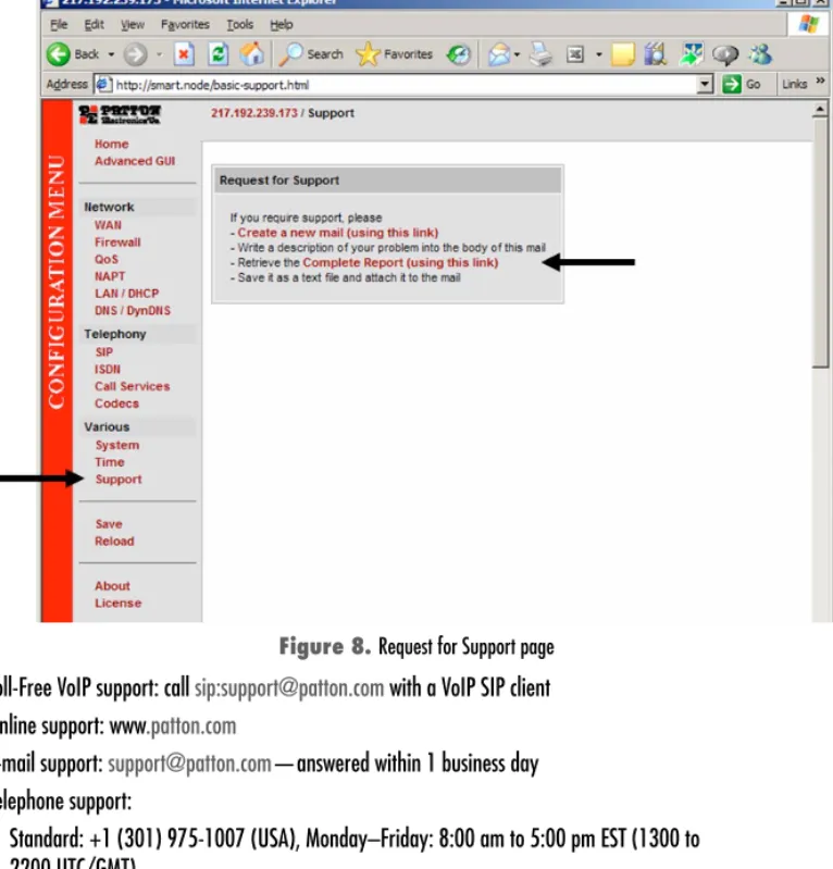
If you contact Patton support, you should have some system information ready to help us better help you. This information allows us to quickly identify what product you are using and how it is configured. Therefore, we integrated a “system report” page that collects all relevant information and presents it to you on one web page. Click on “Support” to access this page – the page also gives you instructions on where to send the report.
Figure 8. Request for Support page Toll-Free VoIP support: call sip:[email protected] with a VoIP SIP client Online support: www.patton.com
E-mail support: [email protected]—answered within 1 business day Telephone support:
• Standard: +1 (301) 975-1007 (USA), Monday–Friday: 8:00 am to 5:00 pm EST (1300 to
2200 UTC/GMT)
• Alternate: +41 (0)31 985 25 55 (Switzerland), Monday–Friday: 8:00 am to 5:00 pm CET (0900 to 1800
UTC/GMT)
A.0 Appendix—Factory default IP addresses
Factory default IP addresses and netmask configuration.B.0 Compliance Information
B.1 Compliance EMC Compliance: • FCC Part 15, Class A • EN55022, Class A • EN55024 Safety Compliance: • IEC 60950-1 • EN60950-1• AS/NZS 60950-1 (SmartNode 4552 only)
PSTN Regulatory Compliance:
• TBR-3
B.2 Radio and TV interference
The SmartNode router generates and uses radio frequency energy, and if not installed and used properly—that is, in strict accordance with the manufacturer’s instructions—may cause interference to radio and television reception. The SmartNode router have been tested and found to comply with the limits for a Class B computing device in accordance with specifications in Subpart B of Part 15 of FCC rules, which are designed to provide rea-sonable protection from such interference in a commercial installation. However, there is no guarantee that interference will not occur in a particular installation. If the SmartNode router does cause interference to radio or television reception, which can be determined by disconnecting the unit, the user is encouraged to try to correct the interference by one or more of the following measures: moving the computing equipment away from the receiver, re-orienting the receiving antenna and/or plugging the receiving equipment into a different AC outlet (such that the computing equipment and receiver are on different branches).
IP Address Network mask
WAN interface Ethernet 0 (0/0) DHCP Client n/a
LAN interface Ethernet 1 (0/1) 192.168.1.1 255.255.255.0
B.3 EC Declaration of Conformity
(See section B.5 “EG-Konformitätserklärung” for German version.)
Product Description: SmartNode 1200, 1400, and 4552
The products described above in the form as delivered are in conformity with the provisions of the following European Directive:
R&TTE Directive 1999/5/EC
Guidelines of the European Parliament and the Committee for the Harmonization of the Legal Regu-lations of the Member States concerning radio equipment and telecommunications terminal equip-ment and the mutual recognition of their conformity.
The signed Declaration of Conformity can be downloaded from www.patton.com/certifications/.
B.4 Approval
The SmartNode is approved for connection to the public ISDN telecommunication network. Anybody may connect the SmartNode to a BRI/S0- or PRI/S2m-ISDN interface and put it into operation.
B.5 EG-Konformitätserklärung
(See section B.3 “EC Declaration of Conformity” for English version)
Produktbezeichnung: SmartNode 1200, 1400, und 4552
Die bezeichneten Produkte stimmen in der von uns in Verkehr gebrachten Ausführung mit den Vorschriften fol-gender Richtlinie überein:
R&TTE 1999/5/EG
Richtlinie des europäischen Parlaments und des Rates zur Angleichung der Rechtsvorschriften der Mitgliedstaaten über Funkanlagen und Telekommunikations-Endeinrichtungen und die gegenseitige Anerkennung ihrer Konformität.
Die unterzeichnete Konformitätserklärung kann heruntergeladen werden von:
www.patton.com/certifications/.
B.6 Zulassung
Der SmartNode ist für die Anschaltung an das öffentliche ISDN Telekommunikationsnetz zugelassen. Er darf durch jedermann an eine BRI/S0- oder PRI/S2m-Schnittstelle angeschlossen und in Betrieb genommen werden.
The safety advice in the documentation accompanying the products shall be obeyed. The conformity to the above directive is indicated by the CE sign on the device.
Die Sicherheitshinweise in der mitgelieferten Produktdokumentation sind zu beachten. Die Konformität mit der oben erwähnten Richtlinie wird durch das CE-Zeichen auf dem Gerät bestätigt.
Copyright statement
Copyright © 2005, Patton Electronics Company. All rights reserved.
The information in this document is subject to change without notice. Patton Electronics assumes no liability for errors that may appear in this document.
Trademarks statement
The term SmartNode is a trademark of Patton Electronics Company. All other trademarks presented in this docu-ment are the property of their respective owners.
Warranty, Trademark, & Compliance Information
For warranty, trademark and compliance information, refer to the SmartNode Getting Started Guide located on the CD-ROM shipped with your SmartNode device or available online at www.patton.com.
In accordance with the requirements of council directive 2002/96/EC on Waste of Electrical and Electronic Equipment (WEEE), ensure that at end-of-life you separate this product from other waste and scrap and deliver to the WEEE collection system in your country for recycling.
NOTES ____________________________________________________________________ ____________________________________________________________________ ____________________________________________________________________ ____________________________________________________________________ ____________________________________________________________________ ____________________________________________________________________ ____________________________________________________________________ ____________________________________________________________________ ____________________________________________________________________ ____________________________________________________________________ ____________________________________________________________________ ____________________________________________________________________ ____________________________________________________________________ ____________________________________________________________________ ____________________________________________________________________ ____________________________________________________________________
NOTES ____________________________________________________________________ ____________________________________________________________________ ____________________________________________________________________ ____________________________________________________________________ ____________________________________________________________________ ____________________________________________________________________ ____________________________________________________________________ ____________________________________________________________________ ____________________________________________________________________ ____________________________________________________________________ ____________________________________________________________________ ____________________________________________________________________ ____________________________________________________________________ ____________________________________________________________________ ____________________________________________________________________ ____________________________________________________________________
NOTES ____________________________________________________________________ ____________________________________________________________________ ____________________________________________________________________ ____________________________________________________________________ ____________________________________________________________________ ____________________________________________________________________ ____________________________________________________________________ ____________________________________________________________________ ____________________________________________________________________ ____________________________________________________________________ ____________________________________________________________________ ____________________________________________________________________ ____________________________________________________________________ ____________________________________________________________________ ____________________________________________________________________ ____________________________________________________________________