Maxwell’s Bridge For Measuring
Unknown Inductance of an Inductor
Rahul biswash
B.Tech(ECE)
E-roll : 130020204021
GD Goenka University
[email protected]
1
Maxwell’s Bridge
A Maxwell’s bridge is a type of Wheatstone bridge used to measure an unknown inductance. Maxwell’s bridge can be used to measure inductance by comparison either with a variable standard self inductance or with a standard variable capacitance.these two measurement can be done by using the Maxwell’s bridge in two different forms.
1.1
Maxwell’s Inductance Bridge
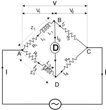
this method is very suitable for accurate measurement of medium inductances. In this method unknown inductance is determine by comparing it with a standard self inductance. Such a bridge circuit is shown in figure 1 in whichL1 is an unknown self inductance of resistorR1,hereL3 is a known variable inductance of
resistorR3whose resistance is constant,R2andR4are pure resistances and D is detector. The magnitude of
L3should be of the same order as that ofL1.The bridge is balanced by varyingL3and one of the resistances
R2 orR4.
The bridge can also be balanced by keepingR2andR4 constant and by varying the resistance of any one of
the other two arms by connecting an additional resistance in that arm.
Figure 1: Circuit Diagram
When the bridge is balanced, the current flowing through detector D is zero and
I1=I2;I3=I4 (1)
Potential Difference across arm AB= Potential Difference across arm AD =V1i.e.
I1Z1=I3Z3=V1 (2)
or
I1(R1+jωL1) =I3(R3+jωL3) =V1 (3)
Potential Difference across arm BC= Potential Difference across arm CD =V2i.e.
or
I1R2=I3R4=V2 (5)
sinceI1=I2andI3=I4
Dividing expression (3) by expression (5) we have Z1
R2
= Z3 R4
(6) or
R1
R2
+jωL1 R2
= R3 R4
+jωL3 R4
(7) Equating the real and imaginary part of both sides separately we have
R1
R2
= R3 R4
(8) or
R1=
R2R3
R4
(9) and
ωL1
R2
= ωL3 R4
(10) or
L1=
R2.L3
R4
(11) Thus value of unknown self inductanceL1 can be determined.
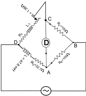
Example 1The four arms of a Maxwell bridge network are as follows:
AB and BC are non-inductive resistance of 100Ω each. DA is a standard variable inductor L of resistance 32.7 Ω and CD comprises a standard variable resistor R in series with a coil of unknown impedance. Balance is obtained when L = 47.8mH and R = 1.36 Ω.Find resistance and inductance of the coil.
Figure 2: Circuit Diagram Solution: Circuit diagram in shown in figure 2
When the bridge is balanced,the product of the resistance of opposite arms are equal i.e.
(R1+R2)R4=R2R3 (12)
or resistance of coil,
R1=
R2R3
R4
−R2 (13)
R1=
100×32.7
100 −1.36 = 31.34ΩAns. (14) In case of balanced position of bridge also
L1=
R2R4
L = 100
100 ×47.8 = 47.8mHAns. (15)
1.2
Maxwell’s Inductance Capacitance Bridge
In this method of measurement of self-inductance,the unknown self-inductance is compared with a standard variable capacitance,the circuit being shown in figure 3.In the circuit L1 is unknown self-inductor and R1
is unknown resistance of inductor,R2,R3 and R4 are known non-inductive resistance and C4 is a standard
Figure 3: Circuit Diagram ImpedanceZ1 =R1 +jωL1.
ImpedanceZ2=R2.
ImpedanceZ3=R3.
ImpedanceZ4= 1 1
R4+ 1
−jXc
= 1 1
R4+jωC4
= R4 1 +jωC4R4
(16) For balanced condition of bridge
Z1Z4=Z2Z3 (17)
or
(R1+jωL1)R4
1 +jωC4R4
=R2R3 (18)
or
R1R4+jωL1R4=R2R3+jωC4R4R2R3 (19)
Equating real and imaginary quantities separately we have
R1R4=R2R3 (20)
and
jωL1R4=jωC4R4R2R3 (21)
or
L1=C4R2R3 (22)
The bridge is perfectly balanced by varyingC4 andR4 which gives independent settings.
The Q-factor of the inductor is given by ωL1
R1 and at balanced condition
Q=ωL1 R1
=ωC4R4R2R3×
R4
R2R3
=ωC4R4 (23)
NOTE:-1.2.1 Quality factor, Q
Reactive components such as capacitors and inductors are often described with a figure of merit called Q. While it can be defined in many ways, its most fundamental description is:
Q=ω engerystored
averagepowerdissipated (24)
Thus, it is a measure of the ratio of stored vs. lost energy per unit time.
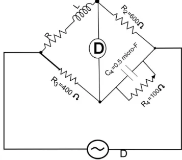
Example 2. Determine the value of R and L of the inductor connected in the bridge circuit shown in fig 4 ;if balance has been obtained.Also determine the Q-factor of the coil.(Reff J.B. Gupta page no. 553)
Figure 4: Circuit Diagram Solution : Resistance of inductor,
R=R2R3 R4
= 600×400
1,000 = 240ΩAns. (25)
Inductance of inductor
L=C4R2R3= 0.5×10−6×600×400 = 120mH (26)
The Q-factor of coil,
Q=ωC4R4= 2Π×1,000×0.5×10−6×1,000 = 3.14Ans (27)
1.3
Advantages
1. This bridge permits the measurement of inductance in terms of capacitance and capacitor have always advantage to an inductor as it gives practically no external flied,so it is more compact and is easier to shield than an inductor
3. The capacitor are smaller in size.
4. In this bridge , balance condition are independent of frequency as the term frequency does not appear in any of balance equation.
5. With the help of this bridge Q-factor of any coil can be measured very easily and quickly by keeping capacitance C4 constant and calibrating dial of variable resistance R4 in terms of Q-factor of coil
directly.
1.4
disadvantages
1. It should be noted that the bridge-balance condition are independent of frequency only, so far as the inductance and resistance of coil under test are themselves independent of frequency. In practice the electrical properties of a coil vary with the variation in temperature, current and frequency etc. 2. The main disadvantage of this bridge is that it requires a variable standard capacitor which is
expen-sive component when calibration to a high accuracy.The bridge is sometimes employed with a fixed capacitor,either because a variable standard capacitor is not available of because it is desired to obtain the higher accuracy possible with a fixed standard capacitor and high-accuracy resistance boxes.