1 Introduction
The Qorivva MPC56xx 32-bit microcontroller family built on Power Architecture ® technology provides a mechanism by
which the e200 core implements interrupts and exceptions. This application note describes a method for decoding the length of VLE instructions, one which is used to correctly increment the returning address of the exception.
2 Overview
In this application note, core exceptions are split into two types:
• Exceptions for which the address located in the SRR0 is increased automatically.
• Exceptions for which the address located in the SRR0 has to be increased manually based on the length of the instruction that caused the exception.
This information is located in the IVORx interrupt chapter in the related e200 Core Reference Manual.
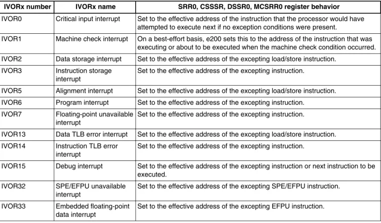
Table 1 highlights IVORx exceptions that require manual incrementing of the return address in the SRR0 register for the e200z7 core. For further information, refer to the "Debug
Freescale Semiconductor
Document Number: AN4648Application Note
Rev. 1, 3/2013VLE 16-bit and 32-bit Instruction
Length Decode Algorithm
by: Pavel Bohacik
© 2013 Freescale Semiconductor, Inc.
Contents
1 Introduction...1 2 Overview...1 3 Machine check interrupt (IVOR1
exception) example...2 4 Book E or VLE instruction decoding...2 5 Decoding 16-bit or 32-bit VLE
instructions...3 5.1 Decoding the condition in C...4 5.2 Decoding the condition in
assembly...5 6 Conclusion...5 7 References...5
Interrupt—Register Settings" table in the Interrupts and Exceptions chapter of document number e200z760RM, e200z760n3 Power Architecture Core Reference Manual.
Table 1. SRR0 register behavior for each IVORx exception (e200z7 core)
IVORx number IVORx name SRR0, CSSSR, DSSR0, MCSRR0 register behavior
IVOR0 Critical input interrupt Set to the effective address of the instruction that the processor would have attempted to execute next if no exception conditions were present.
IVOR1 Machine check interrupt On a best-effort basis, e200 sets this to the address of the instruction that was executing or about to be executed when the machine check condition occurred. IVOR2 Data storage interrupt Set to the effective address of the excepting load/store instruction.
IVOR3 Instruction storage
interrupt Set to the effective address of the excepting instruction.
IVOR5 Alignment interrupt Set to the effective address of the excepting load/store instruction. IVOR6 Program interrupt Set to the effective address of the excepting instruction.
IVOR7 Floating-point unavailable interrupt
Set to the effective address of the excepting instruction.
IVOR13 Data TLB error interrupt Set to the effective address of the excepting load/store instruction. IVOR14 Instruction TLB error
interrupt
Set to the effective address of the excepting instruction.
IVOR15 Debug interrupt Set to the effective address of the excepting instruction or next instruction to be executed.
IVOR32 SPE/EFPU unavailable
interrupt Set to the effective address of the excepting SPE/EFPU instruction. IVOR33 Embedded floating-point
data interrupt
Set to the effective address of the excepting EFPU instruction.
3 Machine check interrupt (IVOR1 exception) example
When an IVOR1 exception occurs (due to memory protection, for example), the e200 core sets Machine Check Save/Restore Register 0 (MCSRR0) to the address of the instruction that was executed or about to be executed when the machine check condition occurred. If a recoverable machine check exception occurred, you should update MCSSR0 appropriately in the IVOR1 handler epilog based on all recommendations mentioned in AN2865, Qorivva Simple Cookbook available at freescale.com.
Freescale e200 cores allow you to use both variable length encoding (VLE) 16-bit and 32-bit instructions and Book E 32-bit instructions. (Book E is not supported by the e200z0 core, however.) When a machine check interrupt occurs, MCSRR0 contains the address of the instruction that was executed when the machine check occurred. To avoid a recurrence of the machine check interrupt, you should properly increment the instruction address in MCSSR0. The increment of the instruction address depends on the type of instruction interrupted by the machine check interrupt. An increment of 4 bytes is required for Book E instructions and VLE 32-bit instructions; an increment of 2 bytes is required for VLE 16-bit instructions.
4 Book E or VLE instruction decoding
More powerful types of e200 cores, like the e200z7, allow a mixed execution of VLE and Book E instructions. For this reason, Book E instruction detection is required when a machine check interrupt occurs.
There are several ways to determine whether a Book E or a VLE instruction was used.
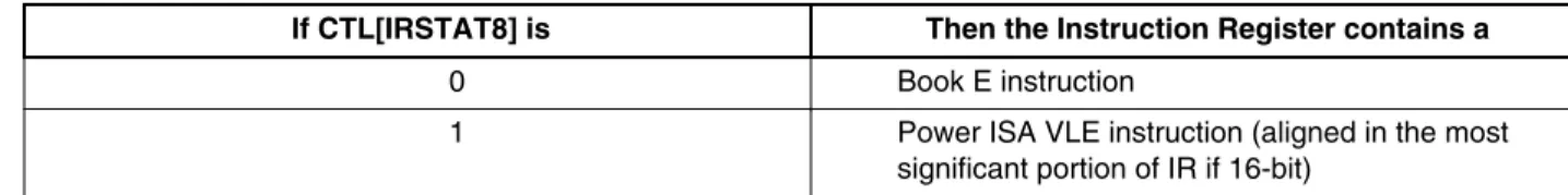
1. Check Instruction Register Status Bit 8 in the Control State Register (CTL[IRSTAT8]) to determine the Power ISA VLE status for the Instruction Register (IR). This is a debug register, so it is not accessible by the main core. See e200z760RM, e200z760n3 Power Architecture Core Reference Manual for further details.
If CTL[IRSTAT8] is Then the Instruction Register contains a
0 Book E instruction
1 Power ISA VLE instruction (aligned in the most significant portion of IR if 16-bit)
2. Check the Power ISA VLE bit in the Memory Management Unit's MMU Assist Register 2 to determine the type of page. Your IVORx epilog should read all valid MMU table entries (MAS1[VALID]) and compare whether the returning address located in Machine Status Save/Restore Register 0 (SRR0) fits one of MMU entries.
If MAS2[VLE] is Then the page is a
0 Standard Book E page 1 Power ISA VLE page
3. Use a global variable. To simplify the procedure with the MMU, which may be undesired because it takes a significant amount of time, you can use a global array that lists memory ranges of VLE or Book E pages and is filled during the definition of MMU entries. Your IVORx epilog then reads SRR0 and determines whether a VLE or Book E instruction was executed based on global array values.
5 Decoding 16-bit or 32-bit VLE instructions
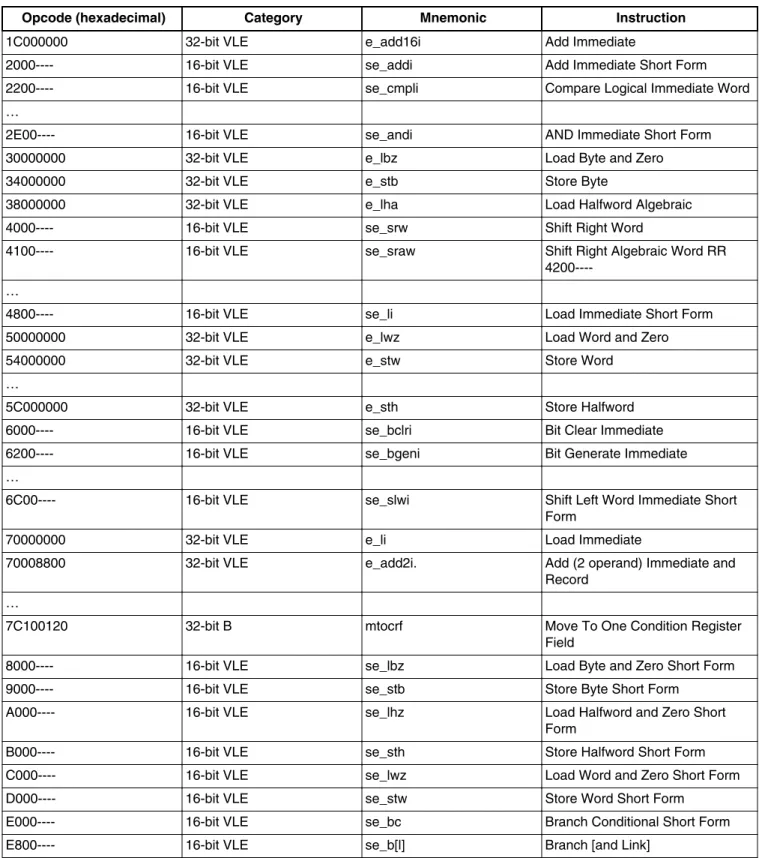
When a VLE instruction has been successfully decoded, the interrupt handler epilog should detect whether a 16-bit or 32-bit VLE instruction has been interrupted. Depending on the type of e200 core, different 32-bit instructions are available. See VLEPEM, Variable-Length Encoding (VLE) Programming Environments Manual, for the "VLE Instruction Set Sorted by Opcode" table, which contains both 32-bit and 16-bit instructions. After detailed investigation, the difference in opcode between all types of 16-bit and 32-bit VLE instructions is easily visible. Table 2, which lists a range of 16-bit and 32-bit VLE instructions, is based on the table from VLEPEM.
Opcode size is determined by the first 4 bits (instruction bus[0:3]). 16-bit operations use encoding 0b0xx0 and 0b1xxx, with the exception of 0b1111, which are reserved operations (32-bit). 32-bit operations use 0b0xx1. As highlighted in the following table, 32-bit instructions contain values 1, 3, 5, and 7 in the most significant byte position of this opcode. 16-bit VLE instruction contains values 0, 2, 4, 6, 8, 9, 0xA, 0xB, 0xC, 0xD, and 0xE in the most significant byte position of this opcode.
Table 2. 16- and 32-bit VLE instruction set ranges
Opcode (hexadecimal) Category Mnemonic Instruction
0000---- 16-bit VLE se_illegal Illegal
0001---- 16-bit VLE se_isync Instruction Synchronize …
0F00---- 16-bit VLE se_cmphl Compare Halfword Logical Short Form
10000000 32-bit VEC vaddubm Vector Add Unsigned Byte Modulo 10000002 32-bit VEC vmaxub Vector Maximum Unsigned Byte …
Table continues on the next page...
Table 2. 16- and 32-bit VLE instruction set ranges (continued)
Opcode (hexadecimal) Category Mnemonic Instruction
1C000000 32-bit VLE e_add16i Add Immediate
2000---- 16-bit VLE se_addi Add Immediate Short Form 2200---- 16-bit VLE se_cmpli Compare Logical Immediate Word …
2E00---- 16-bit VLE se_andi AND Immediate Short Form 30000000 32-bit VLE e_lbz Load Byte and Zero 34000000 32-bit VLE e_stb Store Byte
38000000 32-bit VLE e_lha Load Halfword Algebraic 4000---- 16-bit VLE se_srw Shift Right Word
4100---- 16-bit VLE se_sraw Shift Right Algebraic Word RR
4200----…
4800---- 16-bit VLE se_li Load Immediate Short Form 50000000 32-bit VLE e_lwz Load Word and Zero 54000000 32-bit VLE e_stw Store Word
…
5C000000 32-bit VLE e_sth Store Halfword 6000---- 16-bit VLE se_bclri Bit Clear Immediate 6200---- 16-bit VLE se_bgeni Bit Generate Immediate …
6C00---- 16-bit VLE se_slwi Shift Left Word Immediate Short Form
70000000 32-bit VLE e_li Load Immediate
70008800 32-bit VLE e_add2i. Add (2 operand) Immediate and Record
…
7C100120 32-bit B mtocrf Move To One Condition Register Field
8000---- 16-bit VLE se_lbz Load Byte and Zero Short Form 9000---- 16-bit VLE se_stb Store Byte Short Form
A000---- 16-bit VLE se_lhz Load Halfword and Zero Short Form
B000---- 16-bit VLE se_sth Store Halfword Short Form C000---- 16-bit VLE se_lwz Load Word and Zero Short Form D000---- 16-bit VLE se_stw Store Word Short Form
E000---- 16-bit VLE se_bc Branch Conditional Short Form E800---- 16-bit VLE se_b[l] Branch [and Link]
5.1 Decoding the condition in C
if(VLE_INSTRUCTION) {
if((instruction & 0x9000) == 0x1000) {
// first 4 bits have a value of 1,3,5,7 return address +=4; //instruction was 32-bit }
else {
// first 4 bits have a value of 0,2,4,6,8,9,A,B,C,D,E (and F, but F is reserved) return address +=2; //instruction was 16-bit
} }
5.2 Decoding the condition in assembly
mfspr r5,570 # MCSRR0 -> r5
se_lhz r4,0(r5) # determine opcode @ MCSRR0 e_andi. r3,r4,0x9000
e_cmpli 0x0,r3,0x1000 # check bit 31,28 only
e_bne __machine_check_adjust_for_16bit_opcode se_addi r5,2 # 0xx1 => 32 bit
__machine_check_adjust_for_16bit_opcode:
se_addi r5,2 # all others just 16 bit long mtspr 570,r5 # save adjusted return address
6 Conclusion
This application note describes how to correctly increment the returning address for IVORx exceptions, which do not automatically increase it. Incrementing the returning address is required only for instructions that would cause this exception continuously, causing software to get stuck. You should always correctly handle the root cause of the IVORx exception before incrementing the returning address.
7 References
Document number Title Availability
e200z760RM e200z760n3 Power Architecture Core
Reference Manual freescale.com
VLEPEM Variable-Length Encoding (VLE) Programming Environments Manual
AN2865 Qorivva Simple Cookbook
How to Reach Us:
Home Page: www.freescale.com Web Support:
http://www.freescale.com/support
USA/Europe or Locations Not Listed: Freescale Semiconductor
Technical Information Center, EL516 2100 East Elliot Road
Tempe, Arizona 85284
+1-800-521-6274 or +1-480-768-2130 www.freescale.com/support
Europe, Middle East, and Africa: Freescale Halbleiter Deutschland GmbH Technical Information Center
Schatzbogen 7 81829 Muenchen, Germany +44 1296 380 456 (English) +46 8 52200080 (English) +49 89 92103 559 (German) +33 1 69 35 48 48 (French) www.freescale.com/support Japan:
Freescale Semiconductor Japan Ltd. Headquarters ARCO Tower 15F 1-8-1, Shimo-Meguro, Meguro-ku, Tokyo 153-0064 Japan 0120 191014 or +81 3 5437 9125 [email protected] Asia/Pacific:
Freescale Semiconductor China Ltd. Exchange Building 23F
No. 118 Jianguo Road Chaoyang District Beijing 100022 China
+86 10 5879 8000
Document Number: AN4648 Rev. 1, 3/2013
Information in this document is provided solely to enable system and software implementers to use Freescale Semiconductors products. There are no express or implied copyright licenses granted hereunder to design or fabricate any integrated circuits or integrated circuits based on the information in this document.
Freescale Semiconductor reserves the right to make changes without further notice to any products herein. Freescale Semiconductor makes no warranty, representation, or guarantee regarding the suitability of its products for any particular purpose, nor does Freescale Semiconductor assume any liability arising out of the application or use of any product or circuit, and specifically disclaims any liability, including without limitation consequential or incidental damages. "Typical" parameters that may be provided in Freescale Semiconductor data sheets and/or specifications can and do vary in different applications and actual performance may vary over time. All operating parameters, including "Typicals", must be validated for each customer application by customer's technical experts. Freescale Semiconductor does not convey any license under its patent rights nor the rights of others. Freescale Semiconductor products are not designed, intended, or authorized for use as components in systems intended for surgical implant into the body, or other applications intended to support or sustain life, or for any other application in which failure of the Freescale Semiconductor product could create a situation where personal injury or death may occur. Should Buyer purchase or use Freescale Semiconductor products for any such unintended or unauthorized application, Buyer shall indemnify Freescale Semiconductor and its officers, employees, subsidiaries, affiliates, and distributors harmless against all claims, costs, damages, and expenses, and reasonable attorney fees arising out of, directly or indirectly, any claim of personal injury or death associated with such unintended or unauthorized use, even if such claims alleges that Freescale Semiconductor was negligent regarding the design or manufacture of the part.
RoHS-compliant and/or Pb-free versions of Freescale products have the functionality and electrical characteristics as their non-RoHS-complaint and/or non-Pb-free counterparts. For further information, see http://www.freescale.com or contact your Freescale sales representative.
For information on Freescale's Environmental Products program, go to http://www.freescale.com/epp.
Freescale™ and the Freescale logo are trademarks of Freescale Semiconductor, Inc. All other product or service names are the property of their respective owners. © 2013 Freescale Semiconductor, Inc.