pCO
2Standard Application
Pack Control
Code: FLSTDMFC0A
Version 1.2’s manual
We wish to save you time and money!
We can assure you that the thorough reading of this manual will guarantee
correct installation and safe use of the product described.
IMPORTANT WARNINGS
BEFORE INSTALLING OR HANDLING THE APPLIANCE PLEASE CAREFULLY READ AND FOLLOW THE INSTRUCTIONS DESCRIBED IN THIS MANUAL.
The appliance that this software is dedicated to has been developed to operate risk-free and for a specific purpose, as long as:
• all the conditions specified and described in the installation and operation manual for the device in question are heeded.
• the installation, programming, operation and maintenance of the software are carried out according to the instructions contained in this manual and by qualified personnel;
All other uses and modifications made to the device that are not authorised by the manufacturer are considered incorrect. Liability for injury or damage caused by the incorrect use of the device lies exclusively with the user.
CONTENTS
1 The program ...3
1.1 Main new features in version 1.2 release date 10/02/03 ...3
1.2 Main characteristics ...3
1.3 Starting the unit...3
1.4 The supervisor network ...6
1.5 Meaning of the pCO² inputs / outputs...6
2 Main settings ...7 2.1 Dead zone ...7 2.2 Proportional band...7 2.3 Compressor management...7 2.4 Fan management ...10 3 Special functions ...12
3.1 Compressor time bands...12
3.2 Force devices ...12
3.3 Auxiliary probe management...12
3.4 Energy consumption control function...12
3.5 Calculate estimated efficiency function...12
3.6 Using the GSM modem ...13
3.7 Electronic valve management ...14
3.8 Prevent high discharge pressure (G3) ...14
4 Alarm management ...15
4.1 Alarms with automatic reset ...16
4.2 Alarms with manual reset ...16
4.3 Semiautomatic alarms...16
4.4 Alarm relay ...17
4.5 Alarm log ...17
5 User interface ...18
5.1 Display...19
5.2 LEDs under the buttons ...19
5.3 Extetnal keypad ...19
5.4 Built-in terminal...21
6 List of parameters...22
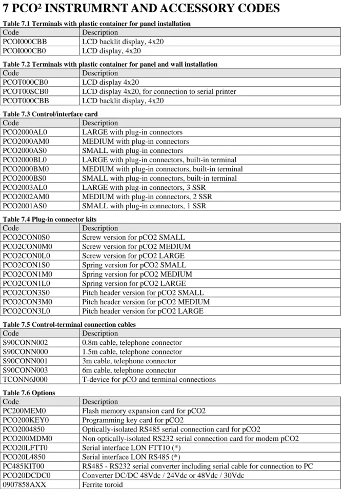
7 pCO² instrumrnt and accessory codes ...31
8 Glossary ...33
9 Supervisor communication variables...34
9.1 Analogue variables ...34
9.2 Digital variables...36
9.3 Integer variables...39
10 Default configurations ...41
1 THE PROGRAM
1.1 Main new features in version 1.2 release date 10/02/03
• The number of fan stages has been increased from 5 to 16. • Program compatible with the pCO1 platform.
• The compressors can also be controlled with NTC temperature probes. • Suction and discharge pressure saved together with the events in the alarm log.
• GSM modem management for remote connections and sending SMS (text) messages upon each alarm event. • Control of the efficiency and the electrical consumption of the system.
• Indication of the electronic valve installed, with signal to the supervisor. • Extended choice of refrigerants (for pressure – temperature conversion).
• Management of a transducer able to measure refrigerant leaks into the environment, with corresponding alarm threshold. • Increased number of languages available: Italian, English, French, German, Spanish.
• New high discharge pressure alarm prevent function.
1.2 Main characteristics
The FLSTDMFC0A “Refrigeration system” application software for pCO² / pCO1 allows the management of a refrigeration system, with the following characteristics:
• display and control of the values measured; by external or built-in LCD terminal; • system control with pressure probes or NTC pressure probes;
• management, according to the number of outputs available, of up to six compressors, each with up to three capacity-control steps (for a total of four outputs per compressor), and up to sixteen condensing fan steps;
• alarm management and consequent saving in the alarm log; • availability of three levels of access to the screens;
• modification of the fundamental operating parameters (set point, differentials, alarm thresholds, time settings); • programming of the time bands (variation of the set point according to time bands);
• multi-language management
• connection to a supervisor/telemaintenance serial line. • send SMS (text) messages to cellular telephones.
The program features some screens for setting the operating values, and others for configuring the unit, all of which are password-protected.
1.3 Starting the unit
1.3.1 Selecting the language for displaying the screens
The application software allows the language of the user interface to be changed at power on. The first screen, after the initial self-test, displays the current language, which can be changed by pressing ENTER.
If no button is pressed, after a few seconds the main screen M0 is displayed (without changing the language). 1.3.2 Initialising the parameters in the permanent memory
The first time that the pCO² is used the data in the permanent memory should be initialised to prevent the use of incorrect for the required control functions.
For this reason, the first time the pCO² is used, the program automatically initialises all the parameters. To perform the same procedure at any other time, follow these steps:
1. Turn the pCO² on; after a certain time in which the check routine is run, the pCO² will display the main screen, M0. During the first installation IGNORE the alarms, as these may be the result of incorrect data in the permanent memory.
2. Press the MENU + PROG buttons to display the password setting screen. This screen prevents access to the configuration branch by unauthorised persons.
3. Enter the password (default 1234), and press ENTER to confirm. 4. Move to the last row: “INITIALISATION ->”, and press ENTER. 5. Press the UP button. The screen V3 will be displayed.
6. Select the configuration model required;
7. Press ENTER and UP, the text “PLEASE WAIT” will be displayed for a few seconds; this mode deletes the permanent memory and enters the default values defined by Carel.
The default values differ depending on the type of board used.
If some standard values are not correct for the required application, the user can always change them by accessing the screen or from the supervisor, making the unit customisable according to the specific application.
The fundamental parameters to be checked are: • the number of devices and their configuration; • the language used;
1.3.3 Hardware keys, PCO200KEY0 for pCO2 / PCO100KEY0
The hardware keys can be used instead of a computer to download the application software to the pCO2 board. 1.3.4 Downloading the program from the hardware key
Connect the key to the pCO2 – pCO1 and proceed as described below:
1. Switch off the pCO2 – pCO1 and remove the “expansion memory” cover with a screwdriver 2. Position the selector on the key towards the key symbol .
3. Insert the key in the corresponding slot.
4. Press Up and Down at the same time and switch the board on. 5. Check that the red LED on the key comes on .
6. Wait until the copy message on the LCD disappears, then release the buttons and confirm by pressing Enter; the data transfer operation takes around 10 seconds.
7. Switch off the pCO2 – pCO1, remove the key, replace the cover and switch the board on again. The board will now work with the program transferred from the key.
1.3.5 Downloading the program from a computer
Obtain the kit code PC485KIT00 and the WinLOAD 32 program, and proceed as follows:
1. Connect the black converter (RS232/RS485) to the power supply using the transformer supplied in the kit, then connect the transformer to the mains.
2. Connect the converter to a free serial port on the computer using the serial cable supplied in the kit.
3. Connect the converter to connector J10 on the pCO2 – pCO1 using a telephone cable (code S90CONN00*). 4. Start the WinLOAD32 program on the computer with the board off.
5. Enter in the “COMM” field the number of the serial port used on the PC (1 for COM1, 2 for COM2). 6. Enter the value “0” in the “pCO² ADD” field.
7. Switch the board on.
8. Wait 15 seconds until the text “OFF LINE” becomes “ON LINE” in the bottom left of the WinLOAD32 screen, or until the yellow LED near the dipswitch on the board flashes; at this point, enter the actual value of the pLAN address of the board in the “pCO² ADD” field (for stand alone applications pCO² ADD =0).
9. In the WinLOAD32 program select “Upload” folder and the “Application” sub-folder. 10. Select the path with the source files of the application software.
11. Press CTRL, then click all of the IUP and BLB/BIN files, then release CTRL.
12. Click the “UPLOAD” button to start the file transfer procedure. This will last between around 1 and 5 minutes. 13. Wait until the text box shows “Upload OK”.
14. Disconnect the telephone cable between the board and the converter, connect the external display if envisaged, then switch the board on and off again.
1.3.6 Basic configuration
According to the board used (SMALL, MEDIUM, or LARGE) and the number of inputs per compressor (screen C3), the number of compressors set can vary from 1 to 6, with between 1 and 3 capacity-control steps, for a total of 4 outputs per compressor, and between 1 and 16 fan steps. In addition, the compressors and the fans can be configured for phase-cutting speed controllers or inverters.
The program checks the type of board (SMALL, MEDIUM or LARGE) that it is working with, and makes the inputs and outputs that can actually be used available.
For the pCO1 controllers, check that the dipswitches used on the board for the configuration of the type of analogue inputs are positioned correctly; for more information, please read the pCO1 manual.
Number of compressors and fans
The first step involves accessing the screen C4 “CONFIGURATION” to set the number of compressors, fans and capacity-control steps to be managed and monitored.
From external terminal:
ENTER MANUFACTURER PASSWORD +
Go to CONFIGURATION then press
Use UP and DOWN to scroll the screens until reaching C4
The number of compressors to be controlled, managed by the intake probe, can be set by directly by the user (screen C4), keeping in mind the number of relay outputs available according to the model: 8 outputs for the Small; 13 outputs for the Medium; 18 outputs for the Large. The pCO², depending on the board used, can manage from a minimum of 1 compressor to a maximum of 6, all with the same capacity, as well as the possibility to rotate operation. The number of condenser fans available ranges from 1 to 16, and can be set directly by the user (screen C4), with the possibility of rotating operation. After having set/modified the number of controlled devices on screen C4 (compressors, fans, capacity-control steps), it is recommended to update the configuration parameters for the outputs E0,E1,..,E9,Ea,Eb.
Output logic
After having accessed screen C4, press once to return back one level Devices
Input positions OUTPUT POSITIONS
use to place the cursor on OUTPUT POSITIONS and press premere
Associate the relays to the devices managed based on the selected configuration (C4).
[The system will automatically search for the first free position in the digital outputs; otherwise the user can scroll the list using the UP - DOWN buttons]
The user can decide which relays to use for the various devices (e.g. first a compressor then a capacity-control step then a fan and so on), also see manufacturer branch, unit configuration E, without needing to modify the electrical system and in any case freely deciding upon the use of the outputs.
Once having completed this operation, proceed to the configuration of the digital inputs:
NOTE: To configure the pCO2 from the built-in terminal follow the procedure described, using the corresponding buttons.
Input logic
To go back one level, press MENU once. Devices
INPUT POSITIONS
Output positions then
Associate the digital inputs to the previously configured devices so as to set the safety functions and the anomalous operation alarms.
The user can decide if the inputs are normally closed (when an alarm is present the contact is open) or normally open (when an alarm is present the contact is closed) (screen G0).
In addition the type of compressor safety devices connected to the inputs can be defined; the possible choices are as follows: A. general: one safety device only per compressor, not delayed with manual reset
B. thermal overload + oil differential: one input dedicated to the thermal overload, not delayed with manual reset, and one input dedicated to the oil differential, delayed with manual reset
C. thermal overload + high/low pressure switch: one thermal overload input, immediate with manual reset, while the pressure switch is immediate with reset set on the screen G2
D. thermal overload + oil differential + high/low pressure switch: includes all three types of alarm The user can decide which inputs to use for the various safety devices.
Example:
If input 6 is used for the compressor thermal overload switch, simply go to the screen D0, move to the row “Thermal comp.1 ID:00”and choose number 6 from the possible free inputs.
NOTE: the software does not allow two devices to be connected to the same input. To reverse two devices, a free input needs to be used (also see branch D, CONFIGURATION section).
Language selection.
The user can set the display language in two ways. The first is at power on, by pressing ENTER; this function can be disabled by setting the parameter on screen V3.
The second is to change the language without re-starting the controller. To do this, from the main screen M0 press PROG ( for the built in terminal, press PROG and go to the row “USER: !” and then press ENTER), then enter the password (default 0); Screen P1 is displayed, press ENTER until the desired language is displayed.
Currently the software manages five languages (Italian, English, French, German and Spanish).
Unit On-Off.
There are various ways to activate or deactivate the controller and the management of the various devices with related alarms (in order of priority):
1. from the alarms: the screen Pe can be used to select if a faulty probe alarm is to turn the unit off or not 2. from the supervisor: the screen Pe is used to enable shut-down from the supervisor
3. from digital input (if configured, C8) in addition to the screen G1, the logic can be selected
1.4 The supervisor network
The pCO2 system allows connection to the main supervisory systems, using interface boards and suitable protocols. In this application program, the following data is exchanged with the supervisor:
• display of the status of the inputs / outputs, • the status of the enabled devices,
• any alarms present and active
• the enabling of the devices, various functions, etc.
Furthermore, a number of parameters can be modified, such as: set point, differential, time settings, unit status, alarm reset, etc. Also see the paragraph Variables used in communication with the supervisor.
1.4.1 Serial cards.
For connection to the supervisory systems, the pCO² is designed to support the main and most common communication standards. As a result, connection cards are available for the following standards:
• optically-isolated RS485 serial card for pCO² PCO2004850
• RS232 modem serial card, not optically-isolated, for pCO² PCO200MDM0
The user may, depending on requirements, decide whether to install the card or not. The card allows connection to a supervisory system for the transmission of all the parameters set in the pCO².
In addition, an external GATEWAY is available for communication with the BACNET protocol. 1.4.2 Communication protocols.
The pCO² line supports and integrates two communication protocols, CAREL PLANT VISOR, MODBUS and GSM MODEM. As well as installing the card, for the correct operation the identification number of the pCO² needs to be set and the card needs to be enabled (V0 and V1), and the communication protocol used needs to be selected.
Each pCO² must have its address defined so that:
" there are no other devices with thesame address on the same serial line
" the addresses of pCO²s on the same serial line must be set in progressive order, starting from no. 1 For further information, refer to the corresponding manual or contact CAREL.
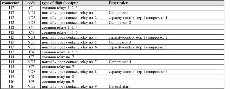
1.5 Meaning of the pCO² inputs / outputs.
This table summarises the inputs - outputs and provides a short description of each.
As the inputs and outputs of the software are completely configurable, the physical connection of the inputs and outputs changes according to which devices are configured; also see the tables on the different configurations that can be set.
In addition, the input/output branch displays what devices are configured and how they are connected.
When using a pCO1 controller, check that the dipswitches used on the board for the configuration of the type of analogue inputs are positioned correctly; for further information refer to the pCO1 installation manual.
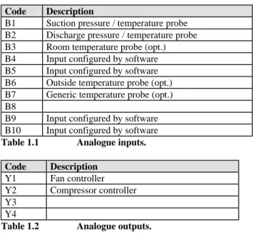
Code Description
B1 Suction pressure / temperature probe B2 Discharge pressure / temperature probe B3 Room temperature probe (opt.) B4 Input configured by software B5 Input configured by software B6 Outside temperature probe (opt.) B7 Generic temperature probe (opt.) B8
B9 Input configured by software B10 Input configured by software
Table 1.1 Analogue inputs.
Code Description
Y1 Fan controller Y2 Compressor controller Y3
Y4
Table 1.2 Analogue outputs.
2 MAIN SETTINGS
2.1 Dead zone
This setting determines a zone around the set point in which no device is activated or deactivated, as a consequence minimising rapid changes in the system pressure and thus stabilising its behaviour.
The devices are activated when the measured value exceeds the limit to the right (measured value greater than SP + DZN, see Figure 1).
The number of devices to be activated varies according to the time elapsed in this situation. At set intervals, the software increases the load by one step. The controller checks the parameter (T0), used to measure the minimum time to remain in the zone for requesting the activation of a further step.
Similarly, the devices are stopped when the measured value falls below the dead zone (measured value less than the set point), and remains there for a period equal to the time between device stop requests (T0); in this case, the first device stops immediately, while the others wait the delay time between stops.
Also see the paragraph on Time settings.
If the next device that should start is off due to a time setting, then the start of another device will be requested, respecting the delay between starts for the devices.
1. Device stop zone 2. Dead zone 3. Device start zone
4. DZN compressor and fan dead zone differential (S8) 5. RP suction pressure read
6. SP Set Point: compressors (S2); fans (S1)
2.2 Proportional band
Proportional band control calculates, based on the parameters (SP, DF and the number of devices set), the various points of activation and deactivation of the devices, so as the various starts and stops are positioned proportionally within the controlled differential.
The example shows the activation of the steps for a system with 4 stages. For each step, by setting the parameters listed above, each individual step has a differential equal to SP + DF/No. steps, for the first, SP + 2 *DF/No. steps for the second, up to SP + DF for the last step.
1. SP Set Point: compressors (S2); fans (S1) 2. DF Differential: compressors and fans (S8) 3. RP Pressure read
2.3 Compressor management
The compressors can be managed with inverter control or as simple ON-OFF stages Inputs Used:
• Suction pressure probe (B1)
• Digital inputs dedicated to the compressor safety devices (ID x) Devices used:
Various digital outputs that depend on the configuration used; Parameters used for the control:
• compressor set point • compressor differential
• minimum compressor set point limit • maximum compressor set point limit
• number of compressors and capacity-control steps • compressors times • type of rotation • SP RP DZN ON OFF 1 2 3 Figure 2.1.1 RP DF ON OFF 4 3 2 1 Figure 2.1.1.1
2.3.1 Compressor management, without inverter Can be configured with or without capacity-control Parameters used for ON OFF control:
number of capacity-control steps capacity-control step times compressor times
Description of dead zone or proportional band operation.
The compressors are managed by the unit based on Set Point and a differential, which can be set on the screen (S1) and on the value read by the intake probe.
In the default configuration, dead zone control is activated - as set on the screen (G5) - with FIFO rotation (G5), respecting the various time settings (see the corresponding paragraph).
For a description of dead zone or proportional band operation, please see the following paragraph. 2.3.2 Compressor management with inverter
If the control is configured with an inverter, no capacity-control can be used Parameters used for inverter control:
• enable inverter • inverter set point • inverter step
• minimum compressor inverter opening Operating description:
The compressor inverter can be activated on the screen (C5), if no capacity-control steps are configured on screen C4. A lower limit can be set for the inverter (G9).
The inverter is managed as follows: case 1 - dead zone control
The inverter is set on the first compressor, which will always be the first on and the last off.
The control requires the setting of a differential (DZNI) for the control of the inverter (screen S6) from the inverter Set Point (SP) and the amount to increase the value by each second.
The output of the inverter of compressor no. 1 starts increasing when the reading of the intake probe exceeds the inverter Set Point + the differential. A decrease occurs when the reading of the intake probe is below the value of the Set Point.
In the zones between the SP and SP + DZNI, the output of the inverter is not changed. The output of the inverter is increased/decreased every second, by the value defined as the inverter step (screen S6)
Caution:when the compressor inverter is enabled and is controlled outside of the dead zone, the compressors are started in the following way:
- compressor 1, which is managed by the inverter, is activated as soon as there is a start request;
- if the request remains, the output of compressor 1 inverter is increased;
- if the request is still present, and the output of the inverter reaches 10 Volts, the other compressors are requested, one at a time, with rotation (if selected) and respecting the time settings.
For deactivation , the following occurs: - the output of the inverter is decreased;
- when the output of the inverter reaches 0 Volt, the other compressors stop, one at a time, respecting the time settings and rotation;
- the last compressor to stop is no. 1. case 2 - proportional band control
The control requires the setting of a set point and a differential (screens S3 and S9). When the value measured by the intake probe is less than or equal to the value of the inverter set point, the output of the inverter is 0 Volt. As the value measured by probe B1 moves away from the set point, the analogue output is increased in proportion to the deviation, until reaching 10 Volts, when the value measured is greater than or equal to the inverter set point + differential.
SP RP DZNI 0 V 10 V
2
Figure 2.2.2.1 SP 0 V 10 V RP V BLI 2 1 3 Figure 2.2.2.22.3.3 Capacity-control parameters
The capacity-control steps are a function of the compressors generally used to balance the working loads between the compressors. This is not valid for single cylinder compressors.
For multi-cylinder compressors, on the other hand, applying the capacity-control steps distributes a percentage of the load inside the compressor (depending on requirements) to each cylinder.
This allows a reduction in energy consumption and the repeated ON/OFF of the compressors, thus optimising the operation and life of the compressors.
Number of capacity-control steps
Manufacturer branch, configuration, screen C4
One, two or three capacity control steps can be selected, with a maximum of 4 relays per compressor.
This parameter is displayed only if there is at least one free output per configured compressor, and if the “Compressor Inverter” functions have not been enabled at the same time.
Capacity-control step logic
Manufacturer branch, general parameters, screen G8
If capacity-control steps are used, this parameter selects the operating logic for the outputs dedicated to the capacity-control steps (normally energised or normally de-energised).
Compressor start mode with capacity-control steps Manufacturer branch, general parameters, screen G7
If the parameter is set to CppCppCpp the software gives the precedence to the complete start of each compressor; while if set to CCCpppppp the software will first switch on all the compressors and then act on the capacity-control steps
Compressor stop mode with capacity-control steps Manufacturer branch, general parameters, screen G7
If set to ppppppCCC, when the compressors are being stopped, first all the capacity-control steps are deactivated and then the corresponding compressors are stopped. This procedure is useful when wanting to limit the number of compressor stops and starts, and consequently extend the compressor working life.
If ppCppCppC is set, when the compressors are being stopped, priority goes to the complete stop of the individual compressor. so as to more frequently alternate which compressors are on (obviously only with FIFO rotation).
2.3.4 Compressor and fan rotation
This is a fundamental function used to balance the operating hours of the devices in the refrigeration system.
It avoids wear and reduces maintenance on a specific device, by distributing operation evenly to the other devices configured. Manufacturer branch, general parameters, screens M G5… Gc
Rotation can be DISABLED (number 1 is always turned on first, then 2 etc., while the highest number compressor always stops first), or FIFO rotation can be selected (the first on is the first off.)
These screens are also used to select the type of compressor and fan control: dead zone (see Dead zone) or proportional band control (see Proportional band) can be selected.
2.3.5 Type of compressor control
Manufacturer branch, general parameters, screen G6
Can be proportional or proportional plus integral (only in proportional band): • Proportional control
Based on the set point entered (screen S1), a proportional band is calculated, the width of which is equal to the differential set (screen S9).
The positions of the control stages of the devices are calculated within this band, according to the number of compressors configured and any capacity-control steps.
• Proportional and integral control
Proportional plus integral control uses the same parameters as for just proportional, calculating the device activation steps according to the set point, differential, and the integration time set (screen G6)
The integration action is doubled if the conditions do not vary after the set time. Number of compressors forced on with probe 1 fault
Manufacturer branch, general parameters, screen Gb.
2.3.6 Compressor time settings
The following is a list of all the time parameters used for compressor management. Time between start requests (dead zone)
Manufacturer branch, general parameters, screen T0
These parameters set the time between the successive start requests for the devices managed by the probes. Present only for dead zone control.
Time between stop requests (dead zone and proportional band in the event of the prevent function) Manufacturer branch, general parameters, screen T1
These parameters set the time between the successive stop requests for the devices managed by probes 1 and 2. Present only for dead zone control or in the event of the prevent function.
Minimum compressor ON time.
Manufacturer branch, general parameters, screen T2
Sets the minimum time (in seconds) the compressors stay on, that is, once activated, must remain on for the time set by this parameter.
Minimum compressor OFF time.
Manufacturer branch, general parameters, screen T2
Sets the minimum time the compressors stay off. The devices are not started again if the minimum time selected has not elapsed since the last stop.
Minimum time between starts of different compressors (proportional band) Manufacturer branch, general parameters, screen T3
Represents the minimum time that must elapse between the start of one device and the next. This parameter allows simultaneous starts to be avoided
Minimum time between starts of the same compressor Manufacturer branch, general parameters, screen T4
Sets the minimum time that must elapse between two starts of the same device, irrespective of the measured value and the set point. This parameter limits the number of starts per hour. If, for example, the maximum allowable number of starts per hour is 10, to guarantee this limit simply set a value of 360 seconds.
Minimum time between capacity-control step activation for the same compressor
Manufacturer branch, general parameters, screen T5
Sets the minimum time that must elapse between the activation of two capacity-control steps or between the start of the compressor and its capacity control steps. The parameter is present only if capacity-control steps have been selected (M_MANUF325 manufacturer branch). This is a safety parameter if rotation with dead zone operation has been selected, as in fact the minimum time between requests also includes the time between the activation of two capacity-control steps or alternatively between the start of the compressor and its capacity-control steps.
2.4 Fan management
The fans can be managed with inverter control or as simple ON-OFF stages Inputs Used:
• Discharge pressure probe
• Digital inputs dedicated to the fan safety devices Devices used:
Various digital outputs that depend on the configuration used Parameters used for the control:
• Fan set point • Fan differential
• Minimum fan set point limit • Maximum fan set point • number of fans • fan times • type of rotation • type of control 0 1 t OFF T_OFF_CP T_ON_CP ON CP t Figure 2.2.4.1
2.4.1 Fan management without inverter
The fans are managed by the unit based on Set Point and a differential, which can be set on the screen (S1) and on the value read by the outlet probe.
In the default configuration, proportional band control is activated, which can be set on the screen (Gc) with FIFO rotation (Gc), respecting the various time settings.
2.4.2 Fan management with inverter Parameters used:
• Fan inverter set point • Fan inverter differential
The fan inverter can be set on the screen (C5). A minimum value can be set for the inverter (G9) The management of the inverter depends on the type of control performed:
case 1 - dead zone control
The control requires a deviation to be set (S4) from the Set Point and the amount to increase the value by each second. Operation in this case is similar to the compressor inverter.
case 2 - proportional band control
When the value measured by probe 2 is lower than the value of the inverter Set Point (screen S4), the output of the inverter is 0 Volt. As the value measured by probe 2 moves away from the inverter set point, the analogue output is increased in proportion to the deviation, until reaching 10 Volts, when the value measured is greater than or equal to the inverter set point + inverter differential.
2.4.3 Fan parameters Fan rotation
Manufacturer branch, general parameters, screen Gc
Rotation can be DISABLED (number 1 is always turned on first, then 2 etc., while the highest number fan always stops first), or FIFO rotation can be selected (the first on is the first off.)
Fan control
Manufacturer branch, general parameters, screen Gc
Dead zone (see Dead zone) or proportional band control (see Proportional band) can be selected. Number of fans forced on with probe 2 fault
Manufacturer branch, general parameters, screen Gd
If the probe 2 failure or not connected alarm is activated, this parameter indicates the minimum number of fans forced on. 2.4.4 Fan time settings
Time between start requests (dead zone)
Manufacturer branch, general parameters, screen T6
These parameters set the time between the successive start requests for the devices managed by the probes. Present only for dead zone control.
Time between stop requests (dead zone)
Manufacturer branch, general parameters, screen T6
These parameters set the time between the successive stop requests for the devices managed by the probes. Present only for dead zone control.
Minimum time between starts of different fans Manufacturer branch, general parameters, screen T7
Represents the minimum time that must elapse between the start of one device and the next. This parameter allows simultaneous starts to be avoided.
3 SPECIAL FUNCTIONS
3.1 Compressor time bands
Clock branch, screens K1, K2 and K3
Programmable time bands have been included, allowing the variation of the Set Point. Pressing the CLOCK button accesses the branch for programming the time bands. Once time band control has been enabled, the start time in hour and minutes of the time band and the corresponding Set Point must be set (K2, K3). This Set Point will be referred to by the control when the current time coincides with that of the time band, and will remain the point of reference for the system until the following time band starts. For example, assuming time bands with the following values, the results below can be obtained :
HOURS/MINUTES SET POINT RESULT
06:00 0.9 bars from 06:00 to 07:00 the Set Point will be 0.9 bars
07:00 1 bar from 07:00 to 10:00 the Set Point will be 1 bar
10:00 1.1 bars from 10:00 to 17:00 the Set Point will be 1.1 bars
17:00 0.8 bars from 17:00 to 6:00 the Set Point will be 0.8 bars
Table 3.1 Example of time band configuration
Four time bands can be set, and in the case where one or more are not used, it is important to attribute these the same values as the previous band so as to not compromise the correct operation of the control.
3.2 Force devices
The individual devices can be activated manually without the time settings, rotation and irrespective of the values measured by the probes. The only support to the control in manual operation is the alarm management. The manual activation of the inverter devices forces the corresponding analogue outputs to the set value.
The manual procedure can be activated only if the unit is OFF; therefore, the parameters are not enabled if the unit is ON. In any case, the procedure finishes automatically after 5 minutes. See MAINT branch button.
3.3 Auxiliary probe management
The software can manage, as well as the inlet and outlet probes, three auxiliary NTC display-only probes; these are enabled on the screen e. The three probes are:
B3 ambient temperature probe, read only or configurable for consumption control
B6 outside temperature probe, used with the electronic expansion valve. Medium and Large boards only
B7 general temperature probe (the name can be set). Medium and Large boards only. Refrigerant leak probe as default. Once enabled, the value of these probes can be seen in the I/O branch
Note: if the intake probe is connected to B7, the general temperature probe cannot be enabled.
3.4 Energy consumption control function
To be able to monitor and manage energy consumption, the ambient probe must be disabled on screen B3.
Reading and display of the instant power, screen Ac, from external current transformer through current input, screen Cf, in kW, to one decimal.
The daily consumption is calculated in kWh to one decimal, starting from a time set by parameter. The monthly consumption is calculated in MWh to two decimals, over a set period of time. The annual consumption is calculated in MWh to two decimals, over a set period of time. The consumption for the current and previous periods are shown, screen To Ad and Ae.
Screen Af displays the TOTAL consumption in MWh to two decimals.
The screens Ag and Ah displays two further consumption totals for set time bands, in kWh.
The user can enter two start and end count times, and the C-day consumption (corresponding to the period between the start and end) and the C-night consumption (period between end and start) can then be displayed.
For example, if the start time is set to 07.00 and the end time to 20.00, the C-day consumption is the band between the start and end. At the end time, the C-night count starts and the C-day value is saved.
The following day, at the start time: C-night ends, C-day is reset and the new C-day count starts. The same is true in reverse for C-night The consumption is displayed for the current band and for the same band on the previous day.
3.5 Calculate estimated efficiency function
The application is able to estimate the efficiency that would be achieved for the same system operating with a thermostatic expansion valve (TXV). The user needs to set four parameters:
TeVirt: System evaporation temperature for operation with TXV (screen Pi)
DEff Te: Efficiency of the system at the evaporation °C (modifications not recommended, preset at 3%, screen Pi) TcVirt: System condensing temperature for operation with TXV (screen Pj)
DEff Tc: Efficiency of the system at the condensing °C (modifications not recommended, preset at 2%, screen Pj) The software automatically calculates the estimate of the increase in efficiency (screen A7).
As well as the instant value, the daytime (DEff%-day), night-time (DEff%-night), daily, monthly and annual averages are displayed (screens A8, A9, Aa, Ab).
3.6 Using the GSM modem
Carefully read and follow the instructions described in the manual GSM MODEM protocol for pCO2, before installing or working on the appliance with a GSM modem.
The pCO2 standard programmable controller for refrigeration systems manages the new pCO2/GSM protocol, which allows the use of a GSM modem to send and receive SMS (text) messages across a GSM network for signalling and resetting active alarms.
A pCO2-pCO1 can be thus connected to a remote supervisor even when a land line is not available. All the properties of the pCO2/Modem protocol are valid, which allows the pCO2-pCO1 peripherals to communicate with a remote supervisor using the standard Carel protocol.
Setting the protocol to GSM modem in screen V1 enables screens Ai, B3, B4 and a parameter B2, for sending a test message. Screen Ai can be accessed to check the status of the GSM modem and the value in percentage of the GSM network signal strength. Screen B3 can be used to set the telephone number of the GSM cellular phone that should receive the text message, the password (for remote supervisor or receiving text messages) and the number of attempts. In screen B4, the first two rows are the “event description” for the alarm log, the third and fourth rows are fields that the user can use to enter the desired text message.
Upon each alarm event, the controller sends, to the cellular phone number set on screen B3, an SMS (text) message containing the alarm log screen and the message entered in screen B4.
Receiving an SMS message
The new protocol also allows a GSM telephone to be used to set the individual variables of the pCO2 via SMS messages. For example, special commands can be sent to reset an alarm or change the value of a set point
WARNINGS
The messages must be sent from a cellular telephone, not via the internet. The variables involved are those in the supervisor variable database The messages sent must use the following format:
.pCO2.PWD.Type1.Index1.Value1.… … … … .TypeN.IndexN.ValueN& with N<=11 where:
PCO2 = Message header.
PWD = Access password; this must be 4 ASCII characters and coincide with the remote access password. If the password is 0001, PWD will be ‘0001’.
Typei = Type of i-th variable to be set; this may be either ‘A’, ‘I’ or ‘D’, respectively Analogue, Integer or Digital variable.
Indexi = Index of the i-th variable to be set; this must be made up of 3 consecutive numbers from ‘0’ to ‘9’. If, for example, the index of the variable is 132, Index will be ‘132’.
Valuei = Value to be set for the i-th variable; this must always be made up of 6 characters, the first being the sign, and the others the numbers from ‘0’ to ‘9’.
If, for example, the value of the variable is 12, Value will be ‘000012’ or alternatively ‘+00012’. If, on the other hand, the value of the variable is –243, Value will be ‘-00243’.
For analogue variables, the value sent is the effective value of the variable multiplied by 10. For example, the value ‘-00243’ corresponds to –24.3.
For digital variables, the possible values are ‘000000’ or alternatively ‘000001’.
N represents the number of variables to be set in a single SMS message. The maximum number, so as to not exceed the threshold of 160 characters per message, is 11.
WARNINGS
• The SMS message must not contain spaces. • The message starts with a dot.
• The fields in the message are separated by dots.
• The message ends with the character ‘&’, not preceded by a dot. EXAMPLES
To reset the digital variable with index 5 on a pCO2 with password = 1234, the SMS message would be as follows: .pCO2.1234.D.005.000000& value index type password header
To set the analogue variable with index 1 to the value -22.4 with an SMS message, the message must be as follows: pCO2.1234.A.001.-00224&.
3.7 Electronic valve management
When enabling the special parameter in screen C9, the pCO2 standard application is able to send a signal to the supervisor system to tell it that the system is working with an electronic valve.
3.8 Prevent high discharge pressure (G3)
In order to prevent the activation of the HP pressure switch (total shut-down of the compressors, with manual reset), a prevention function can be enabled by setting a pre-alarm threshold; this function does not stop the unit completely, while an event is logged at each start and end of the prevention status.
The high pressure prevent function can be activated/deactivated on the corresponding screen G3 (which also includes the set point setting), and is available for any type of configuration, irrespective of the active cooling capacity of the unit.
Inside the Prevent zone the cooling capacity is reduced, and the activation of any compressors is ignored.
As soon as the condensing pressure falls below the Prevent threshold, for a set time (see screen P9, prevent time 1; default 5 minutes) any compressor start requests are ignored. The following method is used to avoid frequent activation of the Prevent function: if the time between the end of the first Prevent action, plus the corresponding 5 minute delay, and the start of the next Prevent action is less than a set time (see screen P9, prevent time 2; default 60s) the "Excessive prevent frequency" alarm is activated, and an event is logged. The "Excessive prevent frequency" alarm is reset automatically, if, within a set time (see screen P9, prevent time 3; default 30 minutes), the Prevent function will not start. This alarm can also be reset manually by the operator, even if the set time (30 minutes) has not yet elapsed.
Set Set+ Prevent Stop HP Cond.P (bars) Band
V(%) Fans
Set: Fan operation set point
Set+Band: Activation point for all the fans Prevent: Start prevent set point
Stop: High discharger pressure alarm threshold, measured by the corresponding probe HP: Pressure switch threshold
Prevent Status (On-Off) Prevent delay No Prevent time Time (minutes)
To enable the Prevent function on screen G3 (manufacturer branch), set ENABLE; the field with the set point will be displayed for entering the discharge pressure.
Screen P9 (user branch) can be used to set the 3 times for the Prevent function.
Prevent Time 1: expressed in minutes, this is the time that starts immediately after the end of the prevent conditions have been verified, in which no compressors are activated.
Prevent Time 2: expressed in seconds, this starts at the end of a prevent action, after the delay time 1; if within this time a subsequent prevent condition occurs, the excessive prevent frequency alarm will be activated.
Prevent Time 3: expressed in minutes, this is the time in which, if the excessive prevent frequency alarm is active, no new prevent actions can be started; the alarm is deactivated automatically.
4 ALARM MANAGEMENT
The unit checks all the procedures of the individual alarms: action, delays, resets and corresponding signals.
When an alarm is activated, it acts on the devices, if enabled, and simultaneously activates: the LED, the buzzer (on the external terminal), the corresponding screen and the corresponding event recording.
To monitor the active alarm simply press the ALARM button, and use the UP/DOWN buttons to scroll any other active alarms. To reset the relay and delete the alarms in the memory, first display the alarm screen and then press the ALARM button again.
The alarm from digital input arises when there is no voltage at the corresponding terminal if the parameter “input logic” is configured as normally closed. Manufacturer branch, general parameters, screen G0.
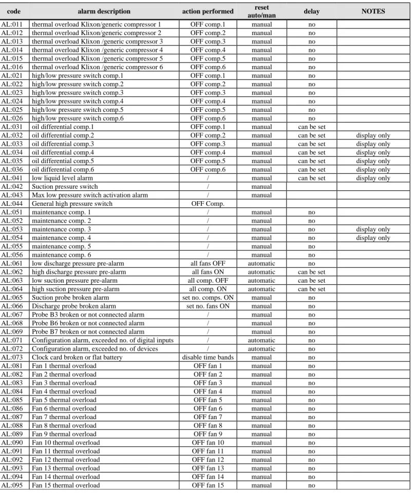
Table 4.1 Alarms managed by the controller
code alarm description action performed reset
auto/man delay NOTES
AL:011 thermal overload Klixon/generic compressor 1 OFF comp.1 manual no AL:012 thermal overload Klixon/generic compressor 2 OFF comp.2 manual no AL:013 thermal overload Klixon /generic compressor 3 OFF comp.3 manual no AL:014 thermal overload Klixon /generic compressor 4 OFF comp.4 manual no AL:015 thermal overload Klixon /generic compressor 5 OFF comp.5 manual no AL:016 thermal overload Klixon /generic compressor 6 OFF comp.6 manual no AL:021 high/low pressure switch comp.1 OFF comp.1 manual no AL:022 high/low pressure switch comp.2 OFF comp.2 manual no AL:023 high/low pressure switch comp.3 OFF comp.3 manual no AL:024 high/low pressure switch comp.4 OFF comp.4 manual no AL:025 high/low pressure switch comp.5 OFF comp.5 manual no AL:026 high/low pressure switch comp.6 OFF comp.6 manual no AL:031 oil differential comp.1 OFF comp.1 manual can be set
AL:032 oil differential comp.2 OFF comp.2 manual can be set display only AL:033 oil differential comp.3 OFF comp.3 manual can be set display only AL:034 oil differential comp.4 OFF comp.4 manual can be set display only AL:035 oil differential comp.5 OFF comp.5 manual can be set display only AL:036 oil differential comp.6 OFF comp.6 manual can be set display only AL:041 low liquid level alarm / manual can be set display only AL:042 Suction pressure switch / manual
AL:043 Max low pressure switch activation alarm / manual AL:044 General high pressure switch OFF Comp.
AL:051 maintenance comp. 1 / manual no AL:052 maintenance comp. 2 / manual no
AL:053 maintenance comp. 3 / manual no display only AL:054 maintenance comp. 4 / manual no display only AL:055 maintenance comp. 5 / manual no
AL:056 maintenance comp. 6 / manual no AL:061 low discharge pressure pre-alarm all fans OFF automatic no AL:062 high discharge pressure pre-alarm all fans ON automatic can be set AL:063 low suction pressure pre-alarm all comp. OFF automatic can be set AL:064 high suction pressure pre-alarm all comp. ON automatic can be set AL:065 Suction probe broken alarm set no. comps. ON manual no AL:066 Discharge probe broken alarm set no. fans ON manual no AL:067 Probe B3 broken or not connected alarm / manual no AL:068 Probe B6 broken or not connected alarm / manual no AL:069 Probe B7 broken or not connected alarm / manual no AL:071 Configuration alarm, exceeded no. of digital inputs / automatic no AL:072 Configuration alarm, exceeded no. of devices / automatic no AL:073 Clock card broken or flat battery disable time bands manual no AL:081 Fan 1 thermal overload OFF fan 1 manual no AL:082 Fan 2 thermal overload OFF fan 2 manual no AL:083 Fan 3 thermal overload OFF fan 3 manual no AL:084 Fan 4 thermal overload OFF fan 4 manual no AL:085 Fan 5 thermal overload OFF fan 5 manual no AL:086 Fan 6 thermal overload OFF fan 6 manual no AL:087 Fan 7 thermal overload OFF fan 7 manual no AL:088 Fan 8 thermal overload OFF fan 8 manual no AL:089 Fan 9 thermal overload OFF fan 9 manual no AL:090 Fan 10 thermal overload OFF fan 10 manual no
code alarm description action performed reset
auto/man delay NOTES
AL:011 thermal overload Klixon/generic compressor 1 OFF comp.1 manual no AL:012 thermal overload Klixon/generic compressor 2 OFF comp.2 manual no AL:013 thermal overload Klixon /generic compressor 3 OFF comp.3 manual no AL:014 thermal overload Klixon /generic compressor 4 OFF comp.4 manual no AL:015 thermal overload Klixon /generic compressor 5 OFF comp.5 manual no AL:016 thermal overload Klixon /generic compressor 6 OFF comp.6 manual no AL:021 high/low pressure switch comp.1 OFF comp.1 manual no AL:022 high/low pressure switch comp.2 OFF comp.2 manual no AL:023 high/low pressure switch comp.3 OFF comp.3 manual no AL:024 high/low pressure switch comp.4 OFF comp.4 manual no AL:025 high/low pressure switch comp.5 OFF comp.5 manual no AL:026 high/low pressure switch comp.6 OFF comp.6 manual no AL:031 oil differential comp.1 OFF comp.1 manual can be set
AL:032 oil differential comp.2 OFF comp.2 manual can be set display only AL:033 oil differential comp.3 OFF comp.3 manual can be set display only AL:034 oil differential comp.4 OFF comp.4 manual can be set display only AL:035 oil differential comp.5 OFF comp.5 manual can be set display only AL:036 oil differential comp.6 OFF comp.6 manual can be set display only AL:041 low liquid level alarm / manual can be set display only AL:096 Fan 16 thermal overload OFF fan 16 manual no
AL:097 Refrigerant gas leak into the environment / manual
AL:098 Prevent in progress OFF compressors automatic no AL:099 Compressors off due to prevent OFF compressors manual no AL:097 Excessive prevent frequency / automatic no
4.1 Alarms with automatic reset
When one or more automatic reset alarms are detected, these are signalled by: • red LED below the ALARM button on;
• buzzer active (with external terminal) ;
• the alarm relay changes status (the logic can be set in the manufacturer branch, general parameters, screen G4), if enabled (manufacturer branch, unit configuration screen C6).
Pressing the ALARM button silences the buzzer and displays the alarm codes.
If the cause of the alarms is resolved, the devices that have shut-down will restart normal operation, and the status of the signal devices changes as follows:
• the alarm relay changes status;
• the buzzer, if not silenced by pressing the ALARM button, stops; • the red LED below the ALARM button flashes.
If, in this situation, new alarms are activated, the initial situation will return.
The red LED flashing informs the user that there have been active alarms during the day and that the causes have now passed. To display the codes of the alarms that were activated, simply go to the alarm log (press the MENU or PROG button for the Built-In terminal, alarm log branch).
4.2 Alarms with manual reset
When one or more manual reset alarms are detected, these are signalled by: • red LED below the ALARM button on;
• buzzer active (with external terminal) ; • the alarm relay changes status.
Pressing the ALARM button silences the buzzer and displays the screens of the activated alarms.
If the cause of the alarms is resolved, the red LED stays on to inform the user that alarms have been activated during the day, and to press the ALARM button to reset this situation. In this situation, the alarm relay remains in an alarm condition.
If, in this situation, new alarms are activated, the initial situation will return.
The devices remain off until the user deletes the alarm messages.
The messages are deleted by pressing the ALARM button when the alarm messages are displayed. If the causes no longer exist, the status of the signal devices changes as follows:
• the alarm relay changes status (switches according to the set logic); • the buzzer, if not silenced by pressing the ALARM button, stops; • the red LED below the ALARM button goes off.
If, on the other hand, the cause of the alarms is still present, the initial situation will return.
4.3 Semiautomatic alarms
The low pressure switch alarm is a semiautomatic alarm. It acts as an alarm with automatic reset, however if it is activated at least 5 times within a set time (default 10 minutes), it becomes an alarm that must be reset manually.
4.4 Alarm relay
The user may decide whether to configure the alarm relay simply by enabling it (C6) and entering the relay to assign to the alarm (Eb). If enabled, a delay time can be set (screen P5) between the activation of an alarm and the change in the status of the signal relay. If the time is set to 0, the activation of the alarm relay is immediate.
4.5 Alarm log
To display the alarm log: press the PRINT button, or enter the Built in terminal by pressing the PROG button twice on the terminal, scroll the rows of the submenus until reaching the alarm log branch and press ENTER.
All the activated alarms, attempts to reset them from the keypad, and black outs are automatically saved in the alarm log. A maximum of 300 events can be saved, all of which can be displayed on the “Alarm log” screen. The type of alarm, the time and date of the alarm and the number of events saved so far, as well as a progressive index number, are all indicated on the screen. When accessing the screen, the last active alarm is displayed. The UP and DOWN buttons can be used to check the previous alarms. Once the maximum number of alarms has been saved, the new events replace the oldest ones. The alarm log can be deleted from screen B2 in the maintenance branch (password-protected). Installing the default values also resets the log.
5 USER INTERFACE
The loop of screens is divided into 4 categories.
USER screens,not password-protected: these screens are in all the branches, except for “prog” and “menu+prog” and show the values read by the probes, the alarms, the operating hours of the devices, the time and the date, and can be used to set the temperature set point and the clock. They are indicated by the symbol “!” in the following table of parameters.
USER screens, password-protected (0000, modifiable): these are accessed by pressing “prog”, and are used to set the main functions (times, set points, differentials) for the devices connected; the screens that refer to functions that are not available are not displayed. They are indicated by the symbol “"” in the following table of parameters.
SERVICE screens,password-protected (0000, modifiable): these are accessed by pressing “maint” and are used to run periodical checks on the devices, calibrate the probes connected, modify the operating hours and manually operate the devices. They are indicated by the symbol “#” in the following table of parameters.
MANUFACTURER screens, password-protected (1234, modifiable): these are accessed by pressing “menu+prog” and are used to configure the system, enable the main functions and select the devices connected. They are indicated by the symbol “$” in the following table of parameters.
The columns in the table below represent the loop of screens, with the first screen (A0, S0…) being the one displayed when pressing the corresponding button, after which the arrow buttons can be used to scroll to the others. The codes (Ax, Bx, Cx…) are displayed in the top right corner of the screens, making them easy to identify. The meaning of the symbols !, "… is explained in the previous paragraph. The symbol PSW indicates that the screens are password protected.
+
$ M0 $ A0 $ I0 $ K0 $ S0 PSW P0 PSW C0 $ M1 $ A1 $ I1 $ K1 $ S1 % P1 & C1
$ M2 $ A2 $ I2 $ K2 $ S2 % P2 CONF. → DISP. IN OUT $ M3 $ A3 $ I3 $ K3 $ S3 % P3 ' C3 ' D0 ' E0 $ M4 $ A4 $ I4 $ K4 $ S4 % P4 ' C4 ' D1 ' E1 $ M5 $ A5 $ I5 PSW S5 % P5 ' C5 ' D2 ' E2 $ A6 $ I6 % S6 % P6 ' C6 ' D3 ' E3 $ A7 $ I7 % S7 % P7 ' C7 ' D4 ' E4 $ A8 $ I8 % S8 % P8 ' C8 ' D5 ' E5 $ A9 $ I9 % S9 % P9 ' C9 ' D6 ' E6 $ Aa $ Ia % Sa % Pa ' Ca ' D7 ' E7 $ Ab $ Ib % Pb ' Cb ' D8 ' E8 $ Ac $ Ic % Pc ' Cc ' D9 ' E9 $ Ad $ Id % Pb ' Cd ' Da ' Ea $ Ae $ Ie % Pe ' Ce ' Db ' Eb $ Af $ If % Pf ' Cf ' Dc $ Ag $ Ig % Pg ' Cg ' Dd $ Ah $ Ih % Ph ' Ch $ Ai $ Ii % Pi PARAM. → ' G0 PSW B0 $ Il % Pj ' G1 ( B1 $ Im % Pk ' G2 ( B2 ' G3 ( B3 ' G4 ( B4 ' G5 ( B5 ' G6 ( B6 ' G7 ( B7 ' G8 ( B8 ' G9 ( B9 ' Ga ( Ba ' Gb ( Bb ' Gc ( Bc ' Gd ( Bd TIMES→ ' T0 ( Be ' T1 ( Bf ' T2 ( Bg ' T3 ( Bh ' T4 ( Bi ' T5 ( Bj ' T6 ( Bk ' T7 ( Bl INITIAL. → ' V0 ( Bm ' V1 ( Bn ' V2 ( Bo ' V3 ( Bp ( Bq ( Br ( Bs
5.1 Display
The display used is an LCD, with 4 rows x 20 columns.
The values and operating information are presented in the form of successive screens. The user can move around the screens using the buttons on the terminal, described as follows:
╔════════════════════╗ ║x Row0 ║ ║Home Row1 ║ ║ Row2 ║ ║ Row3 ║ ╚════════════════════╝
If the cursor is positioned in the top left corner (Home) pressing the UP/DOWN buttons accesses the successive screens in the selected branch.
If the screen includes fields to be set, then pressing the ENTER button moves the cursor to these fields.
Inside the setting fields, the values can be modified, within the limits envisaged, by pressing the UP/DOWN buttons. Once the value required has been set, press the ENTER button to save it
5.2 LEDs under the buttons
Three LEDs are located under the rubber buttons, and indicate respectively:
ON/OFF button green LED - indicates that the instrument is on and in operation. On the built-in terminal, the ENTER button lights up.
ALARM button red LED - indicates the presence of an alarm situation; when flashing, the alarm condition is no longer present.
ENTER button yellow LED - on the external terminal indicates that the instrument is correctly powered green LED - on the built-in terminal, indicates that the instrument is on and in operation.
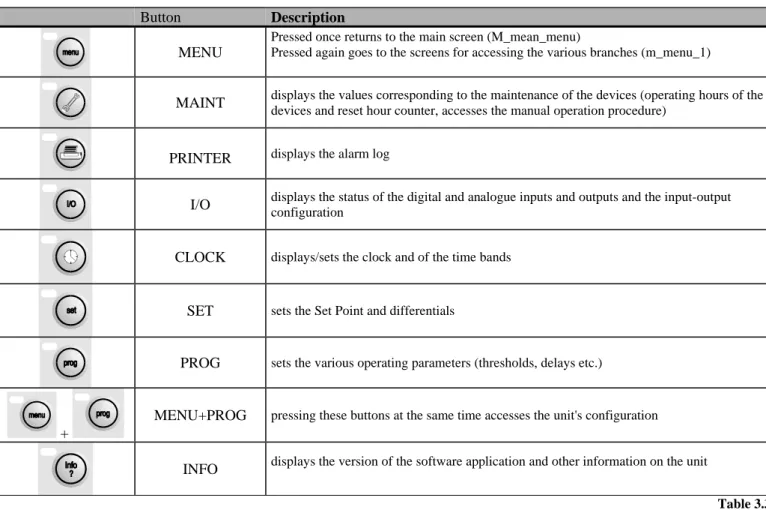
5.3 Extetnal keypad
Layout of the buttons on the pCO external terminal:
MENU MAINT. PRINT I/O CLOCK SET PROG
Table 5.1 Buttons on the external terminal
Button Description
MENU
Pressed once returns to the main screen (M_mean_menu)
Pressed again goes to the screens for accessing the various branches (m_menu_1)
MAINT displays the values corresponding to the maintenance of the devices (operating hours of the
devices and reset hour counter, accesses the manual operation procedure)
PRINTER displays the alarm log
I/O displays the status of the digital and analogue inputs and outputs and the input-output configuration
CLOCK displays/sets the clock and of the time bands
SET sets the Set Point and differentials
PROG sets the various operating parameters (thresholds, delays etc.)
+
MENU+PROG pressing these buttons at the same time accesses the unit's configuration
INFO displays the version of the software application and other information on the unit
Table 3.3.1.1
External silicon rubber buttons.
1. ON/OFF button: switches the unit on and off. The green LED on the button indicates if the unit is on; if the LED is off the unit is OFF
2. ALARM button: used to display the alarms, to perform manual resets and to silence the buzzer. If the button is lit (red) at least one alarm has been activated; if the LED is flashing, an alarm with automatic reset has passed. 3. The UP ARROW has two functions:
• Scroll the various screens when the cursor is in the top left of the display
• If the cursor is inside a numeric field, the button increases or decreases the corresponding value. If the field is a selection, pressing the button displays the available options (not back-lit);
4. The DOWN ARROW:see the UP arrow
5. ENTER button: used to move the cursor around the screens and to save the values of the set parameters. The button is constantly back-lit (yellow), to indicate that the power is on.
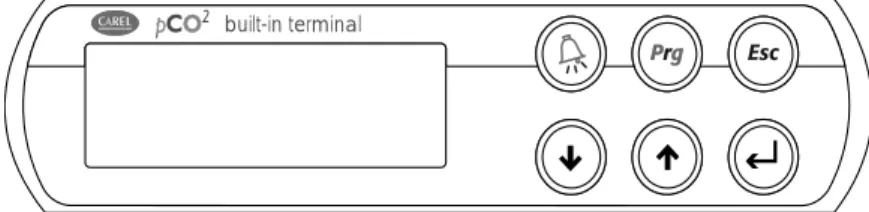
5.4 Built-in terminal
Layout of the buttons on the keypad for the version with built-in display:
built-in terminal
Table 5.2 Layout of the buttons on the built in terminal
ALARM PROG ESC
UP DOWN ENTER
Table 5.3 Buttons on the built in terminal
Button Description
ALARM Has the same functions as the button on the external terminal
UP- DOWN Have the same functions as on the external terminal
ENTER This button has the same functions as the button on the external terminal, while the LED under the button indicates that the unit is on
ESC Returns to the previous branch
PROG Accesses the menu screens for entering the various sub-branches.
The built in terminal, as can be seen from the figures in this paragraph, only has 6 buttons.
To switch the unit on-off, go to screen M5 in the main branch; this is enabled only if a built in terminal is present.
To access the branches of the software, press the PROG button on the built in terminal to enter a menu with two screens. Use the UP and DOWN buttons to move the cursor and highlight the various fields, displayed in capital letters. Pressing ENTER accesses the highlighted branch.
The two screens allow access to the following branches:
1st Menu SET POINT 2nd Menu CONFIGURATION
INPUTS/OUTPUTS TIME / DATA
USER INFO
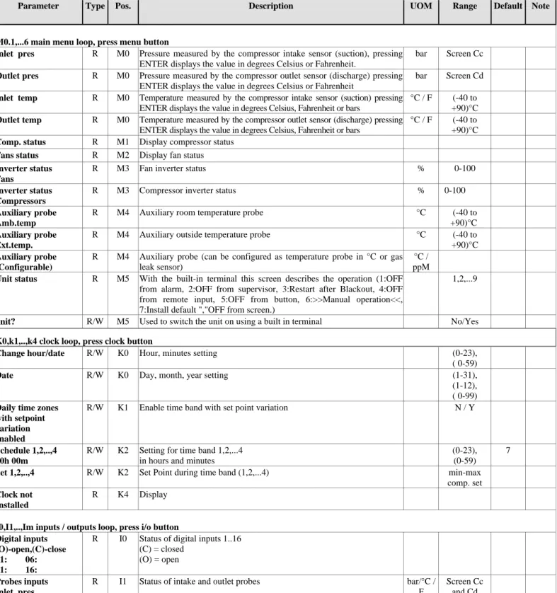
6 LIST OF PARAMETERS
This table contains the list of all the parameters that appear on the screens, with the corresponding description.
Parameter:
string that appears on the screen;
Type:
(R) read-only, (R/W) read/write;
Pos.:
position of the screen in the application, screen index;
Description:
synthetic description of the parameter;
UOM:
unit of measure of the value in question;
Range:
range of possible values for the parameter;
Default:
factory-set value of the parameter
Note:
column available for user notes.
IMPORTANT: Not all the screens listed below will be displayed when scrolling the screens; enabling a
certain type of configuration will mean that new screens are displayed that were previously not available.
Table 6.1 Table of parameters
Parameter Type Pos. Description UOM Range Default Note
M0.1,...6 main menu loop, press menu button
Inlet pres R M0 Pressure measured by the compressor intake sensor (suction), pressing
ENTER displays the value in degrees Celsius or Fahrenheit.
bar Screen Cc
Outlet pres R M0 Pressure measured by the compressor outlet sensor (discharge) pressing
ENTER displays the value in degrees Celsius or Fahrenheit
bar Screen Cd
Inlet temp R M0 Temperature measured by the compressor intake sensor (suction) pressing
ENTER displays the value in degrees Celsius, Fahrenheit or bars
°C / F (-40 to
+90)°C
Outlet temp R M0 Temperature measured by the compressor outlet sensor (discharge) pressing
ENTER displays the value in degrees Celsius, Fahrenheit or bars
°C / F (-40 to
+90)°C
Comp. status R M1 Display compressor status
Fans status R M2 Display fan status
Inverter status Fans
R M3 Fan inverter status % 0-100
Inverter status Compressors
R M3 Compressor inverter status % 0-100
Auxiliary probe Amb.temp
R M4 Auxiliary room temperature probe °C (-40 to
+90)°C
Auxiliary probe Ext.temp.
R M4 Auxiliary outside temperature probe °C (-40 to
+90)°C
Auxiliary probe (Configurable)
R M4 Auxiliary probe (can be configured as temperature probe in °C or gas
leak sensor)
°C / ppM
Unit status R M5 With the built-in terminal this screen describes the operation (1:OFF
from alarm, 2:OFF from supervisor, 3:Restart after Blackout, 4:OFF from remote input, 5:OFF from button, 6:>>Manual operation<<, 7:Install default ","OFF from screen.)
1,2,...9
unit? R/W M5 Used to switch the unit on using a built in terminal No/Yes
K0,k1,..,k4 clock loop, press clock button
Change hour/date R/W K0 Hour, minutes setting (0-23),
( 0-59)
Date R/W K0 Day, month, year setting (1-31),
(1-12), ( 0-99)
Daily time zones with setpoint variation enabled
R/W K1 Enable time band with set point variation N / Y
Schedule 1,2,..,4 00h 00m
R/W K2 Setting for time band 1,2,...4
in hours and minutes
(0-23), (0-59)
7
Set 1,2,..,4 R/W K2 Set Point during time band (1,2,...4) min-max
comp. set
Clock not Installed
R K4 Display
I0,I1,..,Im inputs / outputs loop, press i/o button Digital inputs
(O)-open,(C)-close 01: 06: 11: 16:
R I0 Status of digital inputs 1..16
(C) = closed (O) = open
Probes inputs Inlet pres. Outlet pres.
R I1 Status of intake and outlet probes bar/°C /
F
Screen Cc and Cd