Research Article
a
October
2018
Computer Science and Software Engineering
ISSN: 2277-128X (Volume-8, Issue-10)
Smart Water Management using Real Time Data and ICT:
A
Solution for Water Management Challenges
Yusera Farooq Khan, Abdul Quyoom
Department of Computer Science & Engineering, CoET, BGSB University, Rajouri, Jammu and Kashmir, India [email protected], [email protected]
Abstract— Water is for the most precious resource in the world. It is what separates Earth from the other planets and allows life to thrive. Without it, life would cease to exist. To conserve the water we should use water effectively. In this paper we have take the step to conserve the water that is smart water management system. Smart Water Management (SWM) uses Information and Communication Technology (ICT) and real-time data and responses as an integral part of the solution for water management challenges. The potential application of smart systems in water management is wide and includes solutions for water quality, water quantity, efficient irrigation, leaks, pressure and flow, floods, droughts and much more. By applying SWM infrastructure such as sensors, smart meters, monitors, GSM and satellite mapping, and other data sharing tools to water management, real-time solutions can be implemented and broader networks can work together to reduce current water management challenges. It can be helpful for the future generation also, to some extent we can save the water and use that adequately and wastage will be less.
Keywords— Include at least 5 keywords or phrases
I. INTRODUCTION
Clean, fresh water is a limited resource. With all the severe droughts happening in the world, the limited supply of fresh water is becoming one of our most precious resources. Every person on earth needs the water to survive. While almost 70% of the Earth is made up of water, many parts of the world suffer from clean water shortage [11]. Conserving water is important because it keeps water pure and clean while protecting the environment. Conserving water means using our water supply wisely and be responsible [2]. Only 2% of the Earth’s fresh supply of water is locked in ice caps and glaciers while 97% of the earth’s water is saltwater [5][6]. In this paper we have taken a step to save water although we cannot save the entire wastage of water but it will somehow help to save water [12]. This idea will help to save water in factories where wastage of water is done in every single day. Factories which required number of employees to establish the water saving mode can be replaced by this system of water management [7]. This system is not too costly; it can be afforded by even smaller organizations to prevent wastage of water. We have seen huge amount of water is being wasted in hostels, dams, power plants, and many more companies waste a lot of water. The implementation of Smart Water Management System can help to reduce to water in such conditions and does not require much maintenance [2]. All w need is to do is just register the users and get the limited amount of water.
II. PROPOSED ARCHITECTURE FOR SMART WATER MANAGEMENT
The proposed Architecture in this paper is simple to understand. The Architecture of Water Management is shown in fig.1. The main components of this system include RFID Module, Arduino Nano, Relay Module, Water Tanker, Ultrasonic sensor and many more.
Authentication Process
ISSN(E): 2277-128X, ISSN(P): 2277-6451, pp. 44-49 that when the Level of water is at the fixed threshold of the ultrasonic sensor then the ultra sonic sensor will block the supply of water by turning off the submersible pump with the help of relay Module [8]. If the User tries to get the water more than once from this system , the gsm module Installed in the system will send a message to the registered user that he won’t be able to get water due to the exceed in his water limit.
Fig 1. Architecture of Water Management System
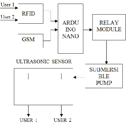
The Block diagram for the proposed methodology is shown below:
Fig 2. Block Diagram of Smart Water Management
Arduino Compiler
The Arduino Integrated Development Environment - or Arduino Software (IDE) – contains a text editorfor writing code, a message area, a text console, a toolbar with buttons for common functions and a series of menus. It connects to the Arduino and Genuino hardware to upload programs and communicate with them. Programs written using Arduino Software (IDE) are called sketches. These sketches are written in the text editor and are saved with the file extension. The editor has features for cutting/pasting and for searching/replacing text. The message area gives feedback while saving and exporting and also displays errors. The console displays text output by the Arduino Software (IDE),including complete error messages and other information.
ISSN(E): 2277-128X, ISSN(P): 2277-6451, pp. 44-49 will reset automatically and begin the upload. With older boards that lack auto-reset, you'll need to press the reset button on the board just before starting the upload. On most boards, you'll see the RX and TX LEDs blink as the sketch is uploaded. The Arduino Software (IDE) will display a message when the upload is complete, or show an error. When you upload a sketch, you're using the Arduino boot loader, a small program that has been loaded on to the microcontroller on your board. It allows you to upload code without using an additional hardware. The boot loader is active for a few seconds when the board resets; then it starts whichever sketch was most recently uploaded to the microcontroller. The boot loader will blink the on-board (pin 13) LED when it starts (i.e. when the board resets).
#include <Wire.h>
#include <LCD.h> #include <LiquidCrystal_I2C.h>
#include <TimeLib.h> #include <DS1307RTC.h>
#include<SoftwareSerial.h> SoftwareSerial rfid (10,11);
//SoftwareSerialcell(3,4); #define echoPin 7
#define trigPin 8 int data1 = 0;
int flag1 = 1; int flag11 = 1; int flag2 = 1;
int flag22 = 1; int flag3 = 1;
int flag33 = 1; int state = 1;
III. COMPONENTS
Voltage Regulator
Voltage regulator is a device which provides fix output voltage in spite of the variable input voltage supplied. It is a three terminal device. Voltage regulator basically comes in two different series: 78XX and 79XX. Voltage regulator under 78XX series are designed for positive inputs i.e. if while 79XX series are designed for negative inputs.
Electronic Voltage Regulator: A simple voltage/current regulator can be made from a resistor in series with a diode. Due to the logarithmic shape of diode V-I curves, the voltage across the diode changes only slightly due to changes in current drawn or changes in the input. When precise voltage control and efficiency are not important, this design may be fine. Since the forward voltage of a diode is small, this kind of voltage regulator is only suitable for low voltage regulated output.
Electromechanical Voltage Regulator: In electromechanical regulators, voltage regulation is easily accomplished by coiling the sensing wire to make an electromagnet. The magnetic field produced by the current attracts a moving ferrous core held back under spring tension or gravitational pull. As voltage increases, so does the current, strengthening the magnetic field produced by the coil and pulling the core towards the field. As voltage decreases, so does the current, releasing spring tension or the weight of the core and causing it to retract. This closes the switch and allows the power to flow once more.
Automatic Voltage Regulator:- Generators, as used in power stations or in standby power systems, will have automatic voltage regulators (AVR) to stabilize their voltages as the load on the generators changes. An AVR is a feedback control system that measures the output voltage of the generator, compares that output to a set point, and generates an error signal that is used to adjust the excitation of the generator. As the excitation current in the field winding of the generator increases, its terminal voltage will increase [11]. The AVR will control current by using power electronic devices; generally a small part of the generator's output is used to provide current for the field winding.
Sensors
ISSN(E): 2277-128X, ISSN(P): 2277-6451, pp. 44-49 electronics, whether as simple as a light or as complex as a computer [7]. Sensors are used in everyday objects such as touch-sensitive elevator buttons (tactile sensor) and lamps which dim or brighten by touching the base, besides innumerable applications of which most people are never aware.
Resistors
A resistor is a passive two-terminal electrical component that implements electrical resistance as a circuit element. In electronic circuits, resistors are used to reduce current flow, adjust signal levels, to divide voltages, bias active elements, and terminate transmission lines, among other uses.
Capacitors
A capacitor is a passive two-terminal electrical component that stores potential energy in an electric field. The effect of a capacitor is known as capacitance. While some capacitance exists between any two electrical conductors in proximity in a circuit, a capacitor is a component designed to add capacitance to a circuit.
Diodes
A diode is a two-terminal electronic component that conducts current primarily in one direction (asymmetric conductance); it has low (ideally zero) resistance in one direction, and high (ideally infinite) resistance in the other. A semiconductor diode, the most common type today, is a crystalline piece of semiconductor material with a p–n junction connected to two electrical terminals.
GSM
GSM (Global System for Mobile Communications) is a second-generation digital mobile telephone standard using a variation of Time Division Multiple Access (TDMA). It is the most widely used of the three digital wireless telephone technologies - CDMA (Code Division Multiple Access), GSM and TDMA. GSM digitizes and compresses voice data, then sends it down a channel with two other streams of user data, each in its own time slot [10].
Submersible Pump
A submersible pump (or sub pump, electric submersible pump (ESP)) is a device which has a hermetically sealed motor close-coupled to the pump body. The whole assembly is submerged in the fluid to be pumped. The main advantage of this type of pump is that it prevents pump cavitations, a problem associated with a high elevation difference between pump and the fluid surface. Submersible pumps push fluid to the surface as opposed to jet pumps having to pull fluids. Submersibles are more efficient than jet pumps. Electric submersible pumps are multistage centrifugal pumps operating in a vertical position. Liquids, accelerated by the impeller, lose their kinetic energy in the diffuser where a conversion of kinetic to pressure energy takes place. This is the main operational mechanism of radial and mixed flow pumps.
Relay Module
The module is triggered, high trigger current less than 5mA, part of the 51 single-chip IO port output capability is weak, pull or increase the drive capability of the circuit, Introducing the Relay Module [9]. A relay is an electrical switch that opens and closes under the control of another electrical Circuit. In the original form, the switch is operated by an electromagnet to open or close one or many sets of contacts. It was invented by Joseph Henry in 1835. Because a relay is able to control an output circuit of higher power than the input circuit, it can be considered to be, in a broad sense, a form of an electrical amplifier. A relay will switch one or more poles, each of whose contacts can be thrown by energizing the coil in one of three ways:
Normally - open (NO) contacts connect the circuit when the relay is activate d; the circuits disconnected when the relay is inactive. It is also called a FORM A contact.
Normally - closed (NC) contacts disconnect the circuit when the relay is activated; the circuit is connected when relay is inactive. It is also called FORM B contact or “break” contact.
Change-over or double-throw contacts control two circuits; one normally open contact and one normally –closed contact with a common terminal. It is also called a Form C
“transfer “contact.
Connectors
ISSN(E): 2277-128X, ISSN(P): 2277-6451, pp. 44-49 light-emitting diode (LED)
A light-emitting diode (LED) is a two-lead semiconductor light source. It is a p–n junction diode, which emits light when activated [6]. When a suitable voltage is applied to the leads, electrons are able to recombine with electron holes within the device, releasing energy in the form of photons. This effect is called electroluminescence, and the colour of the light is determined by the energy band gap of the semiconductor. An LED is often small in area (less than 1 mm2) and integrated optical components may be used to shape its radiation pat
Water Sensor Detector
Water sensor brick is designed for water detection, which can be widely used in sensing rainfall, water level, and even liquid leakage. Connecting a water sensor to an Arduino is a great way to detect a leak, spill, flood, rain, etc [9][1]. It can be used to detect the presence, the level, the volume and/or the absence of water. While this could be used to remind you to water your plants, there is a better Grove sensor for that. The sensor has an array of exposed traces, which read LOW when water is detected.
IV. SOFTWARE IMPLEMENTATION
Arduino is a both an open source software library and an open-source breakout board for the popular AVR micro-controllers. The Arduino IDE (Integrated Development Environment) is the program used to write code, and comes in the form of a downloadable file on the Arduino website. The Arduino board is the physical board that stores and performs the code uploaded to it. Both the software package and the board are referred to as “Arduino.”
1. Connecting the Arduino Connecting an Arduino board to your PC is quite simple. On Windows:
1. Plug in the USB cable – one end to the PC, and one end to the Arduino board.
2. When prompted, select “Browse my computer for driver” and then select the folder to which you extracted your original Arduino IDE download.
3. You may receive an error that the board is not a Microsoft certified device – select “Install anyway”. 4. Your board should now be ready for programming.
When programming your Arduino board it is important to know what COM port the Arduino is using on your PC. On Windows, navigate to Start->Devices and Printers, and look for the Arduino. The COM port will be displayed underneath. Alternatively, the message telling you that the Arduino has been connected successfully in the lower-left hand corner of your screen usually specifies the COM port is it using.
2. Preparing the Board
Before loading any code to your Arduino board, you must first open the IDE. Double click the Arduino.exe file that you downloaded earlier. A blank program, or “sketch,” should open.
The Blink example is the easiest way to test any Arduino board. Within the Arduino window, it can be found under File->Examples->Basics->Blink.
3. Loading Code
The upper left of the Arduino window has two buttons: A checkmark to verify your code, and a right-facing arrow to upload it. Press the right arrow button to compile and upload your program to your Arduino board. The black bar at the bottom of the Arduino window is reserved for messages indicating the success or failure of code uploading. A “Completed Successfully” message should appear once the code is done uploading to your board. If an error message appears instead, check that you selected the correct board and COM port in the Tools menu, and check your physical connections. It is very important that you do not use pins 0 or 1 while loading code. It is recommended that you do not use those pins ever. Arduino code is loaded over a serial port to the controller [6]. Older models use an FTDI chip which deals with all the USB specifics. Newer models have either a small AVR that mimics the FTDI chip or a built-in USB-to-serial port on the AVR micro-controller itself.
V. CONCLUSION
ISSN(E): 2277-128X, ISSN(P): 2277-6451, pp. 44-49 already employ legacy systems that are customized to the specific needs of the water value chain and the solutions vary across different providers, while recent technology provide new approaches. Heterogeneous connectivity is only one part of the challenge. Even more importantly is the interoperability at the data layer as a diverse set of sensors from different manufacturers produce heterogeneous data flows with different representations. Proposal model overcomes the human effort into fill the tank. It is economical and environmental friendly. Implementation results in time and most importantly water saving.
VI. FUTURE SCOPE
This proposal has enormous potential and may be used in various other ways, due to its efficient design.
In future we can modify this system in a way tha the user will be able to get water multiple times in a day.
Use a float switch in a tank, so that the system automatically shuts the pump down, when it’s full.
Use it in conjunction with a solar panel , so that the entire system will become eco-friendly.
We can extend it for reservoirs, water supply units and societies by also controlling the flow of water which would prove useful in water conservation.
REFERENCES
[1] S. Fang et al., "An Integrated System for Regional Environmental Monitoring and Management Based on Internet of Things", IEEE Trans. Ind. Inform., vol. 10, no. 2, pp.1596-1605, May 2014.
[2] Michele Mutchek, Eric Williams ,“Moving Towards Sustainable and Resilient Smart Water Grids,” in Challenges 2014 , March 2014.
[3] S. Chouhan and K. Halonen, "A simple all MOS voltage reference for RFID applications," in NORCHIP, 2013, Nov 2013, pp. 1-3.
[4] Wang, Shuhai et al, "Design and Application of Distance Measure Ultrasonic Sensor", Published in Advances in Mechanical and Electronic Engineering, 2013, Springer, pages 109-114, ISBN 978-3-642-31528-2.
[5] Michael Hogan, C.: Water pollution, Encyclopedia of Earth. Topic ed. Mark McGinley; ed. in chief C. Cleveland. National Council on Science and the Environment, Washington, DC (2010).
[6] Al-Sabhan, W., Mulligan, M., Blackburn, G.A.: A real-time hydrological model for flood prediction using GIS & the WWW. Computer, Environment and Urban Systems 27(1), 9–32 (2003).
[7] Schütze1, M., Campisano, A., Colas, H., Vanrolleghem, P., Schilling, W.: Real-Time Control of Urban Water Systems. In: International Conference on Pumps, Electromechanical Devices and Systems Applied to Urban Water Management PEDS 2003, Valencia, Spain, April 22-25 (2003).
[8] Wan, P., Lemmon, M.D.: Distributed Flow Control using Embedded Sensor-Actuator Networks for the Reduction of Combined Sewer Overflow (CSO) Events. In: 46th IEEE Conference on Decision and Control, pp. 1529–1534 (2007).
[9] Suñer, D., Malgrat, P., Leitão, P., Clochard, B.: COWAMA (Coastal Water Management) Integrated and Real Time Management System of Urban Water Cycle to Protect the Quality of Bathing Waters. In: 11th International Conference on Urban Drainage, Edinburgh, Scotland, UK (2008).
[10] Todolí, D., Santonja, S., Sempere, V.: Enabling Quick Deployment Wireless Sensor Networks for Smart Cities. In: 9th International Workshop on Factory Communication Systems, Lemgo-Detmold, Germany (2012). [11] Zhang, B., & Liu, J. (2010, November). A kind of design schema of wireless smart water meter reading system
based on zigbee technology. In E-Product EService and E-Entertainment (ICEEE). 2010 International Conference on (pp. 1-4).