Proceedings of the
3
rdInternational Workshop on
Multi-Paradigm Modeling
(MPM 2009)
Code Generation with the Model Transformation of Visual Behavior
Models
Tam´as M´esz´aros and Tiham´er Levendovszky and Gergely Mezei
10 pages
Guest Editors: T. Levendovszky, L. Lengyel, G. Karsai, C. Hardebolle Managing Editors: Tiziana Margaria, Julia Padberg, Gabriele Taentzer
Code Generation with the Model Transformation of Visual Behavior
Models
Tam´as M´esz´aros1and Tiham´er Levendovszky2and Gergely Mezei3
1[email protected],3[email protected]
Department of Automation and Applied Informatics
Budapest University of Technology and Economics, Budapest, Hungary
Institute for Software Integrated Systems Vanderbilt University, Nashville, TN, USA
Abstract: There exist numerous techniques to define the abstract and the concrete syntax of metamodeled languages. However, only a few solutions are available to describe the dynamic behavior (animation) of visual languages. The aim of our re-search is to provide visual modeling techniques to define the dynamic behavior of the languages. Previously, we have created languages to describe animation. In this paper, we describe how these models can be processed by model transformation techniques. We elaborate the main steps of the transformation and show the details as well. We use graph rewriting-based model transformation, therefore we provide a highly generic solution which can be easily modified, and analyzed with the tech-niques borrowed from the field of graph rewriting. The termination analysis for the presented method is also provided.
Keywords:Metamodeling, Animation, Model Transformation, VMTS
1
Introduction
Specific Modeling (DSM) has gained increased popularity in software modeling. Domain-Specific Modeling Languages (DSMLs) can simplify the design and the implementation of sys-tems in various domains. Domain-specific visualization helps to understand the models for do-main specialists not familiar with programming.
A popular way to define DSMLs is metamodeling. Metamodels define a vocabulary of model elements for a specific language by describing the available model elements, their properties and the relations between the elements. This definition is often referred to as the abstract syntax of the language. However, metamodeling is not meant to describe the visual representation, the concrete syntax, or the editing behavior of modeling items. Based on the metamodel, a default concrete syntax can be generated, but the description of customized visualization - including colors, sizes and layouting - usually needs additional modeling techniques.
Multi-paradigm modeling [MV02][MV04][VLM02] is a special, straightforward way to apply
offers a higher level of model composition techniques. The integration of orthogonal models is achieved by the modeling environment and the model processors. Multi-paradigm modeling
addresses and integrates three orthogonal directions of research [VLM02]: (i) multi-formalism
modeling, which addresses building models using different formalisms and designing transfor-mations between them; (ii) model abstraction that covers the description of models at different abstraction levels; (iii) metamodeling, which means formally defining models as formalisms. Language engineering is a key factor in Multi-Paradigm Modeling (MPM). Since MPM strongly builds on metamodeling, the applied language engineering methods must also be generic enough to support various metamodels.
Besides the generic methods to build the abstract and concrete syntax of a visual language, only a few solutions are available to describe the dynamic behavior (”animation”) of the models created by metamodeling. By animation, we mean both the visualization of automated model manipulation and the manipulation of the presentation without modifying the underlying model itself. Recent solutions usually bind visualization properties to model properties, and achieve animation by manipulating model properties. Model properties are usually modified with model transformation or direct API calls.
In [MMC09], we have already presented an integrated solution to describe the dynamic be-havior of the models in a generic and visual way. In our approach, we separate the model and its animation logic, and provide visual languages to define the animation of either the model elements or only their visualization. We apply the multi-paradigm approach in the sense of sepa-rating the animation description into different domains: (i) framework integration, (ii) animation logic specification, and (iii) user interface description. The integration of the models is per-formed with both references between models of different domains and by the model processors. The integration of external components or frameworks into our environment is supported with a visual language and a code generator, thus, the animation logic can handle all components in a uniform way.
To be able to execute the visual behavior models with high performance, instead of the run-time interpretation of the models we generate executable source code from them and compile the source code into reusable dynamic linked libraries. We perform the code generation with graph
rewriting-based [EEPT06] model transformation. In this paper, we present the transformation
steps used to build the model of the source code from the animation models. The presented solution is not specific to VMTS, it can be adapted to any metamodeling environment which implements our animation framework.
2
Background
Visual Modeling and Transformation System [VMT09] is a general purpose metamodeling
PortPN PortTimer PortViews PortModels GetDiagramView Default Selecting GettingView Highlighting Firing
[no fireable transitions] PortPN:EventGetFireableTransition [fireable transition] PortViews:EventGetView [PortViews:EventGetView_] PortViews:EventHighlight [PortTimer:Tick] [PortTimer:Tick] PortPN:EventFire PortViews:UnHighlight EH_UI (… ) PNAnimator
PortModels PortViews PortPN PortTimer
Port Mode ls P ortVie ws EH_Pe triNe t (…) Po rtPN EH_T ime r (…) Po rtT im er Initialize EH_GT PortGT ProcessNextCFEdge ProcessStartNode Matching ApplyCurrentMatch ApplyInternalCausalities ApplyInternalCausality Initialized PreNextCFEdge PostNextCFEdge PreStartNode PostStartNode PreDecision PreEndNode PreRuleNode PreInitMatch PreMatching PreApplyMultipleMatch PreApplyCurrentMatch PreInternalCausalities PreInternalCausality PostInternalCausality PostInternalCausalities PostApplyCurrentMatch PostApplyMultipleMatch PostRuleNode AgsiCFEdge InternalCausalityResult AgsiCFEndNode TrafoOutputPlaces AgsiInternalCausality IAgsiCFNode AgsiRuleExecutionResults
Animator state machine High level animation model
Event handler model Event handler implementation Animated model . Animation engine gen. ref. E N V IR O N M E N T .
Domain knowledge and simulation engines
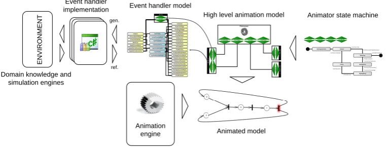
Figure 1: The Architecture of the VMTS Animation Framework
2.1 The VMTS Animation Framework (VAF)
The VMTS Animation Framework (VAF) [MMC09] is a flexible framework supporting the
real-time animation of models both in their visualized and modeled properties. The architecture of
VAF is illustrated in Figure1.
VAF separates the animation of the visualization from the dynamic behavior (simulation) of the model. For instance, the dynamic behavior of a graphically simulated statechart is really different from that of a simulated continuous control system model. In our approach, the domain knowledge can be considered a black-box whose integration is supported with visual modeling techniques. Using this approach, we can integrate various simulation frameworks or self-written components with event-driven communication. The animation framework provides three visual languages to describe the dynamic behavior of a metamodeled model, and their processing via an
event-driven concept. The key elements in our approach are theevents. Eventsare
parametriz-able messages that connect the components in our environment. The services of the presentation
framework, the domain-specific extensions, possible external simulation engines (
ENVIRON-MENT block in Figure1) are wrapped with event handlers, which provide an event-based
in-terface. Communication with event handlers can be established using events. The definition of event handlers is supported with a visual language. The visual language defines the event
handler, its parameters, the possible events, and their parameters - calledentities(Event handler
modelin the figure). The default implementation of an event handler can be generated [LM09]
based on the interface of the wrapped objects (Implementationblock).
The animation logic can be described using an event-driven hierarchical state machine, called
Animator(Animator state machineblock). We have designed another visual language to define
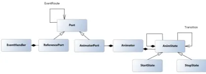
these state machines. The metamodel of this language is depicted in Figure2. The state machine
consumes and produces events. The transitions of the state machine are guarded by conditions (Guard property) testing the input events and fire other events after performing the transition (Action property). States also define anAction property, which describes an operation that is
executed when the state becomes active. The state space of theAnimators can be extended using
Figure 2: The metamodel of the VMTS animation description language
to) another state machine or an event handler. The events produced by the event handlers and
the state machines are scheduled and processed by a DEVS [ZKP00] based simulator engine
(Animation Engine).
The event handlers and the state machines can be connected in a high-level model (High level
animation model). The communication between components is established through ports. Ports can be considered labeled buffers, which have a configurable size. Note, that both the
high-and low-level languages are defined by the same metamodel (Figure2), however, based on their
application they can be considered as two different languages.
2.1.1 Generated source files
Our implementation is based on the C# language, however, the presented solution can be easily adopted to arbitrary object-oriented programming languages. On executing an animation, both the high-level model and the low-level state machines are converted into source code, which highly builds on our DEVS-based simulation engine.
From each state-machine model (from eachAnimator) an individual class is generated, which
implements the behavior described by the state machine. Furthermore, aConfigurationclass is
also generated from the high-level model, this class wires the animator-classes and the event-handler instances together, and initializes the simulation framework.
The structure of the animation files is depicted is listed below:
namespace VMTS.VAF {
public class <AnimatorName> : Simulator {
//Ports of the animator implemented by properties public Port <PortName> {get; private set;} ... public <AnimatorName>(Coordinator coordinator)
: base(coordinator) { } <Variables of the animator> public override void Init() {
//Initialization of the ports <PortName> = new Port(this); <PortName>.Capacity = <capacity>;
<PortName>.Circular = <isCircular>; ... public override void BuildUp() {
startState = new VMTS.VAF.State(this, null, null); currentState = startState;
//Initialization of the states
<container state>); ...
//Initialization of the transitions
<fromState>.AddTransition(new Transition(this, <toState>, <guard condition>, <action>), <isInternal>);
}}}
As one can see, theInitmethod initializes the ports, and theBuildUpmethod creates the states,
and connects them with transitions. Theguard conditionand theactionassigned to a transition
is expressed using anonym methods.
The structure of the configuration files is the following:
namespace VMTS.VAF { class Configuration {
public Configuration() {
coordinator = new Coordinator(); Init();
}
public Configuration( Coordinator _coordinator) { coordinator = _coordinator;
Init(); }
private void Init() {
//instantiation of generated animator classes
<animator field> = new <animator type>(coordinator);... coordinator.Simulators.Add(<animator field>);...
//instantiation of event handler classes
<event handler field> = new <event handler type>(coordinator); coordinator.EventHandlers.Add(<event handler field>);...
<setting event handler parameters> //registering connections
coordinator.AddMapping(<from>.<fromPort>, <to>.<toPort>);... }
<Animator field declarations> <Event handler field declarations> }}
TheCoordinatorclass instantiated in constructor represents the interface towards the simulation
engine. In the Init method the animators and event handlers are instantiated, and registered
towards the coordinator, furthermore, the connections between the components (animators and event handlers) are also registered.
3
Transformation Models
The model of the generated source code uses the VMTS implementation of a C# DOM, which
is very similar to the CodeDOM [COD] of Microsoft. Our DOM implementation builds on
a general code generation and parsing technique presented in [AL09]. The control sequence
of the transformation is depicted in Figure 3. The sequence can be departed into two
well-separated parts: part (1) creates the individual animation classes for eachAnimatorelement and
Figure 3: The control sequence of the transformation rules
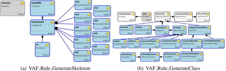
(a) VAF Rule GenerateSkeleton (b) VAF Rule GenerateClass
Figure 4: Creating the skeleton of the animation source code
3.1 Processing the state machines
TheVAF Rule GenerateSkeleton( Figure4) rule creates the model for the source file, the default
namespace (VMTS.VAF) and the necessary namespace references. The rule is executed
exhaus-tively, meaning that it is repeated until a valid match (an unprocessed animator) is found. After finishing this rule, an output file with default content is generated for each animator.
The VAF Rule GenerateClassis illustrated in Figure 4. The rule matches anAnimator and
its connecting namespace element (the relation between the Animator and the namespace is
expressed with not an edge, but with an attribute reference). Then the rule creates a class (class anim) element in the output model, and adds a constructor with base constructor call
and the skeleton of theInitmethod. The rule is executed in an exhaustive manner again.
Afterwards, theVAF Rule Property Portsrule matches eachPortinside an animator and
gen-erates a C# property for each of them within the appropriate class, furthermore, it also
cre-ates the initialization code for each port within the Init method of the class element. The
VAF Rule Method BuildUp rewriting rule matches each Animator and their connecting class
again, and creates aBuildUpmember method beginning with the initialization of thestartState
andcurrentStatemember variables.
3.1.1 Processing the states
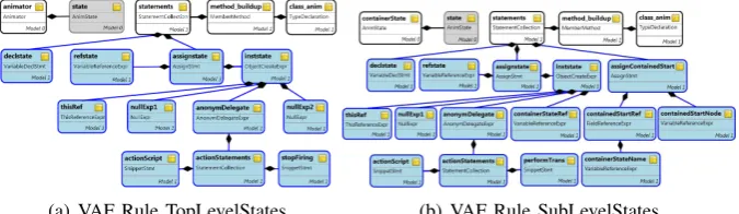
The following two rules (VAF Rule TopLevelStatesandVAF Rule SubLevelStates) are depicted
in Figure5. They are used to generate the model of the connecting code for the states contained
directly by theAnimator (top-level) and for the states contained by another states (sub-level).
(a) VAF Rule TopLevelStates (b) VAF Rule SubLevelStates
Figure 5: Processing states
top-level state:
State stateXXXX;
stateXXXX = new State(this, null, null);
or
stateXXXX = new State(this, delegate() { <action script> }, null);
If an action is defined for the state, then the second version is selected, in case of which the action is specified with the help of an anonym method. The selection is ensured by assigning inverted
application conditions to thenullExp1 andanonymDelegate rule nodes: the affected elements
are created only if the condition can be satisfied. The anonym method-version is selected in
case of top-levelStopnodes as well: the simulation engine is stopped by sending a stop event
to the framework (thestopFiring node is conditionaly created as well). Note, that the lastnull
parameter in the constructor call of theStateclass denotes that the states do not have a container
state.
TheVAF Rule SubLevelStatesis somewhat similar to the top-level version. One difference is,
that atStop states we do not have to stop the simulation, but to notify the framework to check
the outgoing transitions of the container state as well (see the conditionaly createdperformTrans
node). Another difference is, that the container state parameter is set (containerStateRef) in the
constructor call. Furthermore, if a containedStartnode is processed, theContainedStartproperty
of the container state object is set to the internal start state object (assignContainedStartbranch
in the figure). Both rules are executed exhaustively. When aStateis processed, the rule creates an
attribute-level reference from theStateelement to theclass animelement. The existence of this
reference is set as a negative application condition for the rule, therefore, eachStateis processed
exactly once, and the execution terminates. We also prescribe the existence of this reference as
a positive application condition between thecontainerStateand theclass animelement, thus we
can ensure, that the code model for a contained state is generated only if its container state is already processed.
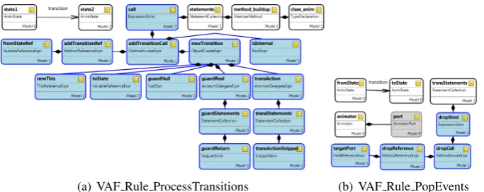
3.1.2 Processing transitions
Transition edges between two states are processed by theVAF Rule ProcessTransitionsand the
(a) VAF Rule ProcessTransitions (b) VAF Rule PopEvents
Figure 6: Processing transitions
TheVAF Rule ProcessTransitionsrule matches transitions in an exhaustive manner, and
gen-erates the following code fragment for each of them inside theBuildUpmethod of the connecting
class:
<stateFrom>.AddTransition(new Transition(this, <stateTo>, delegate(){ return <guard condition>;},
delegate(){ <action script> }), false);
We can get the container class easily, as we have created a reference between each state and the
connectingclass animnode. The last parameter (isInternal= false) denotes, that this transition
is an internal one (triggered by a timer), or an external one, triggered by external events. At each
execution of the rule, the selectedtransitionedge is flagged, so that it cannot be processed twice.
TheVAF Rule PopEventsrule generates aportXXXX.Drop();command for each port triggered by the selected transition. The rule receives the transition to be processed as a parameter from the previous rule, and checks each port in an exhaustive way, whether it is used in the guard
script of the actual transition. TheDropmethod call consumes the topmost event from the target
port, and only from those ports, which were triggered by the transition.
As one can see, theVAF Rule ProcessTransitionsand theVAF Rule PopEventsrule forms a
cycle: they cycle exists, if each transition has been processed, including the verification of each port for each transition.
3.2 Generating the configuration class file
The configuration class is generated by the rules in the block (2) in Figure3. TheVAF Rule CO Skeleton
rule generates the skeleton of the class: type declaration, two constructors, and an empty Init
method. TheVAF Rule CO InitAnimrule creates a member variable for eachAnimatorelement,
and initializes them in theInitmethod. Similarly, theVAF Rule CO InitEHrule creates member
variables for the event handler elements, and initializes them. Finally, theVAF Rule CO EventRoutes
processes the EventRoute edges, registers the connections between the ports of the connected
components:
coordinator.AddMapping(
Figure 7: The VAF Rule EventRoutes rule
TheVAF Rule CO EventRoutesrule is illustrated on Figure7.
Note, that on Figure7theAddMappingmethod call is modelled twice. As theEventRoutescan
be bi-directional as well (depending on theirDirectionproperty), a reverse direction
PortMap-pingcan also be added. The reverse direction is created conditionally based on the settings of
theEventRouteedge.
4
Termination Analysis of the Transformation
Except for the VAF Rule ProcessTransitions and the VAF Rule PopEvents rule-pair, there are
no directed cycles in the transformation control flow graph. Therefore, we can examine the termination of the remaining rules separately.
In case of theVAF Rule GenerateSkeletonrule, the processing of anAnimatoris denoted by
creating an attribute reference between theAnimator (animator node) and the affected
names-pace declaration (nsnode). The existence of such a reference is assigned as a negative application
condition to this rule. Thus, during exhaustive execution, eachAnimatornode is processed
ex-actly once, and the rule terminates, as soon as there are not any unprocessedAnimators. The
termination of theVAF Rule GenerateClassrule can be proven on a similar basis. That case the
associatedAnimatorandNamespaceelements can be exactly matched using the attribute
refer-ence, and eachNamespace element is flagged after processing it. The existence of this flag is
assigned again to the rule as a negative application condition, thus the rule is executed exactly
once for eachAnimator.
The termination of the remaining exhaustively executed rules can be proven based on the
presented two cases. TheVAF Rule ProcessTransitionsrule is executed not exhaustively, but in
a cycle. In each cycle, the rule flags the actually processedTransitionedge, thus it cannot be
matched again. As the followingVAF Rule PopEventsrule does not change this flag (and that
rule terminates as well), the cycle exits as soon as each transition has been matched exactly once. As each rule in the transformation terminates, and the only cycle in the control flow exits after a finite number of steps, the entire transformation terminates as well.
5
Conclusion
providing dynamic animation for models. This paper presents a graph rewriting-based model transformation, which turns the behavior models into executable source code. By using this transformation, our final goal is now reachable. Moreover, by using a graph-rewriting based approach, we can analyze the properties of the transformation. Due to the limits of this paper we have analyzed only the termination properties of our solution, but with a little extension of the transformation we could also verify e.g. the liveness or other correctness properties of the input state machines. The presented approach is not specific to VMTS or to the C# language, but can be easily adopted to any other modeling environments using a similar DEVS-based simulation engine.
Bibliography
[AL09] L. Angyal, L. Lengyel. Synchronization of Textual and Visual Representations of
Evolving Information in the Context of Model-Based Development. InIn Proceedings
of the IEEE Eurocon 2009 Conference. Pp. 468–443. St Petersburg, Russia, May 2009.
[COD] Microsoft CodeDOM website.
http://msdn.microsoft.com/en-us/library/650ax5cx.aspx
[EEPT06] H. Ehrig, K. Ehrig, U. Prange, G. Taentzer.Fundamentals of Algebraic Graph
Trans-formation. Springer, Berlin, illustrated edition edition, 2006.
[LM09] T. Levendovszky, T. M´esz´aros. Tooling the Dynamic Behavior Models of Graphical
DSLs. InIn proceedings of the 13th International Conference on Human-Computer
Interaction. San Diego, USA, July 2009.
[MMC09] T. M´esz´aros, G. Mezei, H. Charaf. Engineering the Dynamic Behavior of
Metamod-eled Languages.Simulation, Special Issue on Multi-Paradigm Modeling, 2009.
[MV02] P. J. Mosterman, H. Vangheluwe. Guest editorial: Special issue on computer
auto-mated multi-paradigm modeling.ACM Trans. Model. Comput. Simul.12(4):249–255,
2002.
[MV04] P. J. Mosterman, H. Vangheluwe. Computer Automated Multi-Paradigm Modeling:
An Introduction.Simulation: Transactions of the Society for Modeling and Simulation
International, Special Issue: Grand Challenges for Modeling and Simulation80:433– 450, 2004.
[VLM02] H. Vangheluwe, J. de Lara, P. J. Mosterman. An Introduction to Multi-Paradigm
Mod-eling and Simulation. InIn Proceedings of the 2002 Conference on AI, Simulation and
Planning in High Autonomy Systems. Pp. 9–20. Lisboa, Portugal, 2002.
[VMT09] VMTS Team. Visual Modeling and Transformation System website. 2009.
http://vmts.aut.bme.hu
[ZKP00] B. P. Zeigler, T. G. Kim, H. Praehofer.Theory of Modeling and Simulation. Academic