ISSN:
2277
–
9043
International Journal of Advanced Research in Computer Science and Electronics Engineering (IJARCSEE) Volume 2, No 5, May 2013485
All Rights Reserved © 2013 IJARCSEESmart Home Control using Lab VIEW
Akshatha N Gowda
(1), Girijamba D L(2), Rishika G N
(3), Shruthi S D
(4), Niveditha S(5)Department of Electronics & Communication Engineering Bahubali College of Engineering, Shravanabelagola, Hassan Dist.
Abstract- Smart home is a house that has intelligent control over the activities performed frequently in daily life to achieve more comfortable and safety life. A smart home is equipped with special structured wiring to enable occupants to program an array of automated home electronic devices by entering a single command. Smart home implementation is based on the Lab VIEW software. This project includes many subsystems such as internal light system, external light system, burglary alarm system and temperature system.The aim of this project is to map the processes yielding optimal utilization of smart home technology, to ensure as many users as possible having access to the technology most relevant for their needs. It minimizes the power losses and it provides safety for us and for Smart home. The smart home technology provides totally different flexibility and functionality than the conventional installations.
Keywords: Automation, Lab view, Smart home, Security
I .INTRODUCTION
A. Smart Home
Smart home automation has been developed to automatically achieve some activities performed frequently in daily life in order to obtain more comfortable and easier life. Smart home technology is a collective term for information and communication technology (ICT) as used in houses, where the various components are communicating via a local network. The technology can be used to monitor, warn and carry out functions according to selected criteria.
Smart home system uses advanced computer technology and automatic control technology, which combines the subsystem into a control system including lighting control, temperature control and burglar alarm system.
The smart house has two interfaces
1. Computer interfacing
2. Remote control unit interfacing
In computer interfacing, Lab VIEW software is the main controller unit which controls all the subsystems in the home. In addition to Lab VIEW interface for the smart house, remote control interfacing is used to monitor internal lighting system, external lighting system, temperature system, burglary alarm system[1][2].
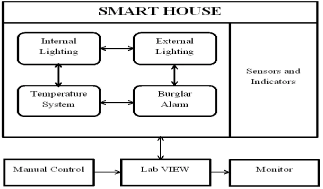
Fig 1. shows the block diagram of smart home. Smart house mainly consists of electronic and electrical equipments. They include sensors and indicators in order to sense and indication of the signal. All the subsystems are connected to Lab view software as the main controller unit of the system. Lab View takes various inputs from connected sensors and processes it according to defined program and then it provides logical output to whole house power system.
The Lab VIEW software will control the internal lighting, external lighting, temperature, fire alarm, burglar alarm in the house. Each component usually performs a single function and there is no synchronization with other components that is security systems that include burglar alarm system that signals the occurrence of a burglary, lighting system that include the internal lighting of the house, and the external lighting outside the house, temperature system for air conditioner controlling.
486
All Rights Reserved © 2013 IJARCSEEFig 1. Smart Home Block Diagram
B. Lab VIEW
Lab VIEW stands for Laboratory Virtual Instrumentation Engineering Workbench. It started in 1983 by a company National Instruments which famously stands for NI. Like C, JAVA, the Lab VIEW software is known as „G‟ language. Lab view is mainly designed for complex problems[3][6][7]. Lab VIEW is a graphical programming language used to create programs called VI which are in a pictorial form called a block diagram, which eliminates a lot of the syntactical details of other programming languages like C and MATLAB that use a text based programming approach. Lab VIEW is available for all the major platforms and is easily portable across platforms. It is simple and flexible, since it is a graphical approach no need of writing programs of 100 lines like other program languages. Each VI has two windows-Front Panel and Block Diagram windows. Front Panel is user interface which has controls and indicators. Block Diagram is program code which shows data travels on wires
from controls through functions to indicators. The major drawback for Lab VIEW not into application is its cost. Thus presently Lab VIEW application are restricted to only high scale applications in industrial levels and yet to shift on the home level. The advantage of Lab VIEW in home automation not only makes it easier to design but also increases the accuracy and speed of the system[6][7].
The rest of the paper is organized as follows: Section II focuses on the design of the system and Section III gives the concluding remarks.
II. DESIGN
ISSN:
2277
–
9043
International Journal of Advanced Research in Computer Science and Electronics Engineering (IJARCSEE) Volume 2, No 5, May 2013487
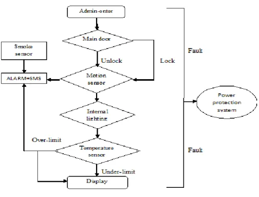
All Rights Reserved © 2013 IJARCSEEFig 2. Flow Chart for Smart House
A LAB VIEW CONTROL
The Lab VIEW will control the internal lighting, external lighting, temperature, burglar alarm systems in the house.
Internal Lighting System:
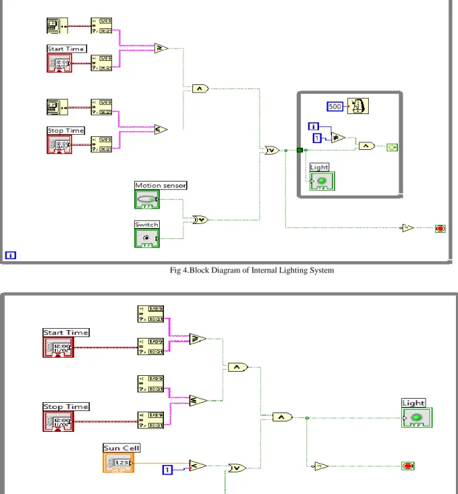
The internal lighting system consists of a motion sensor and lamps which there are connected to Lab VIEW software program. This system will make an automatic lighting in the home when there is any movement inside it. The motion sensor detect whether there is any human presence in the building or not. If not it will send a signal to lab VIEW and it switch off the device in the building. If there is human presence the device will be switched on automatically. If we don‟t want the lamp to glow, it can be manually switched off. The timer circuit is used for some specific area where the lamp glows fpr a fixed period of time.
External Lighting System:
External lighting system consists of suncell, dimmers and lamps which are in contact with lab VIEW software program. External lighting system depends on the reading of sun cell. The output of the
sensor will be in analog form. Depending on the time of morning and night time the Lab VIEW software program control the status of external light lamps which is as shown in Fig 3. Dimmer can use to make a small lamp lighting percentage. In early morning and in evening, the dimmers will be on. Due to environmental changes, depending on the sun cell value lamp may even glow in noon so that timer‟s circuit is used.
488
All Rights Reserved © 2013 IJARCSEEFig 4.Block Diagram of Internal Lighting System
Fig 5. Block Diagram of External Lighting System
Temperature System:
When motion sensor detects the human presence in the building both internal lighting and air conditioning systems are activated. The main object
ISSN:
2277
–
9043
International Journal of Advanced Research in Computer Science and Electronics Engineering (IJARCSEE) Volume 2, No 5, May 2013489
All Rights Reserved © 2013 IJARCSEEroom temperature sensor and critical value of temperature that required.
When the room temperature sensed value is greater than or less than the critical temperature, then
lab VIEW sends the signal to the device to cool or hot it up to the critical temperature and then maintain constant critical temperature.
Fig 6. Block Diagram of Temperature System
Figure 7. Block Diagram of Burglar Alarm System
Burglar Alarm Systems:
The LABVIEW software based home alarm system which act as a security guard of the home. The basic purpose of a home alarm system is to keep us and our family safe, and keep our home safe from crime. The home alarm system is created in lab view
by setting a suitable code for alarm to work that code is fixed.
490
All Rights Reserved © 2013 IJARCSEEand will be closed after few minutes. The time delay is fixed according to the user.
If the code is not matched with the fixed value of code then it indicates wrong code and then buzzer alarm will ring.
B REMOTE CONTROL UNIT
Remote control unit is another interfacing device used in smart house application. Remote control used to send control signal to the central control unit in the system to make specific operation which is connected to Lab VIEW software. There are three parts in the remote control system that is transmitter unit, central receiver unit, and rooms receiver units. Transmitter unit enables the user to control the two difference receiver units. The receiver part in the remote control unit is Central receiver unit which is in contact with the Lab VIEW to make some central operation in the house. Room receiver unit is to control a room load via remote Control.
III. CONCLUSIONS
The main objective of this paper is to increase the accuracy and speed of the system and to monitor the internal lighting system, external lighting system, temperature system and security system. Smart home can minimize power losses and can provide safety for Smart home. Smart home provides fully automatic, secured and energy efficient system. The smart home technology provides totally different flexibility and functionality than the conventional installations and environmental control systems.
REFERENCES
[1] Dr. Basil Hamed , “The Design and Implementation of Smart House Control Using Lab VIEW”, International Journal of Soft Computing and
Engineering (IJSCE), Volume-1, Issue-6, January 2012.
[2] Kunal Kumar, Aditya Kumar, Anand Sharma, Abhishek Anand, Ajit Singh Pawar & Ajay Kumar,
“Vision of Smart Sustainable Home & Home
Application Made Real, Using Labview” ,
Undergraduate Academic Research Journal (UARJ), Volume-1, Issue-2, 2012.
[3] B V Sumangala & K Bhargava Ram, “Advantages of LabVIEW over Embedded System in Home
Automations”, International Conference on
Advancement in Engineering Studies & Technology, July 2012.
[4] Guneet Kour, Jaswanti, “Labview Based Alarm
Systems in Home”, UNIASCIT, Volume- 2, No 3,
2012.
[5] Rosslin John Robles and Tai-hoon Kim, “A
Review on Security in Smart Home Development”,
International Journal of Advanced Science and Technology,Volume- 15, 2010.
[6] Lab VIEW user Manual, 2003 Edition, National
Instruments.
[7] http://www.ni.com/labview/