Charles University in Prague
Faculty of Mathematics and Physics
MASTER THESIS
Bc. Luk´
aˇs Mejdrech
Networking and TCP/IP stack for HelenOS
system
Department of Software Engineering
Master thesis supervisor: Mgr. Martin Dˇeck´y
Study programme: Computer Science, Software systems
Acknowledgements I wish to thank to my thesis supervisor, Mgr. Martin Dˇeck´y, for his advice and direction in this research. I owe the greatest gratitude to my family, for making this thesis possible and their constant patience and support.
I hereby declare that I have created this work completely on my own and used no other sources or tools than the ones listed, and that I have marked any citations accordingly. I agree with lending and publishing this work.
Prohlaˇsuji, ˇze jsem svou diplomovou pr´aci napsal samostatnˇe a v´yhradnˇe s pouˇzit´ım citovan´ych pramen˚u. Souhlas´ım se zap˚ujˇcov´an´ım pr´ace a jej´ım zveˇrejˇnov´an´ım.
N´azev pr´ace: Networking a TCP/IP stack pro syst´em HelenOS Autor: Bc. Luk´aˇs Mejdrech
Katedra: Katedra softwarov´eho inˇzen´yrstv´ı Vedouc´ı pr´ace: Mgr. Martin Dˇeck´y
E-mail vedouc´ıho: [email protected]
Abstrakt: V t´eto pr´aci studujeme implementaci TCP/IP subsyst´emu. D˚uraz je kladen na n´avrh a implementaci respektuj´ıc´ı koncept operaˇcn´ıho syst´emu s mikroj´adrem. Praktickou ˇc´ast´ı pak byl v´yvoj TCP/IP subsyst´emu pro syst´em HelenOS. Nejprve jsou pops´any koncepty s´ıt’ov´e architektury a TCP/IP subsyst´emu obecnˇe. N´asleduj´ı specifick´e aspekty kladen´e syst´emem s mikroj´adrem. D´ale je uveden n´avrh architek-tury a implementaˇcn´ı rozhodnut´ı vlastn´ı implementace.
Kl´ıˇcov´a slova: s´ıt’ov´e architektury, TCP/IP subsyst´em, HelenOS, ovladaˇce s´ıt’ov´eho rozhran´ı
Title: Networking and TCP/IP stack for HelenOS system Author: Bc. Luk´aˇs Mejdrech
Department: Department of Software Engineering Supervisor: Mgr. Martin Dˇeck´y
Supervisor’s e-mail address: [email protected]
Abstract: Within this work we study networking and TCP/IP stack implementa-tion. The main interest is directed to the TCP/IP stack design and implementation respecting the microkernel operating system concept. The practical part was a de-velopment of a TCP/IP stack for the microkernel operating system HelenOS. First, we describe the networking and the TCP/IP stack concept in general. The special aspects of the microkernel concept follow. For the practical part, the architecture design and implementation decisions are included.
Contents
1 Introduction 6 1.1 Motivation . . . 6 1.1.1 History . . . 6 1.1.2 Implementation . . . 7 1.2 Goals . . . 71.3 Structure of the thesis . . . 8
1.3.1 Style conventions . . . 8
2 Context of the thesis 10 2.1 Networking stack models . . . 10
2.2 HelenOS specific design . . . 12
2.2.1 Kernel code . . . 12
2.2.2 Modularity . . . 12
2.2.3 Inter–process communication . . . 13
2.3 Qemu emulator . . . 13
2.4 N. E. T. . . . 14
3 Networking stack design 15 3.1 New networking stack . . . 15
3.1.1 Extent of the implementation . . . 15
3.1.2 Architecture . . . 16
3.1.3 Modular architecture . . . 16
3.1.4 Packet management system . . . 20
3.2 Networking stack modules . . . 21
3.2.1 Central configuration module - net . . . 22
3.2.2 Network interface drivers . . . 23
3.2.3 Network interface layer . . . 25
3.2.4 Inter–network layer . . . 29
3.2.5 Transport layer . . . 35
3.2.6 Application programming interface - libsocket . . . 37
3.2.7 Applications . . . 38
4 Discussion 40 4.1 Implementation . . . 40
4.1.2 Support structures . . . 41
4.1.3 Modules . . . 46
4.1.4 Startup module - netstart . . . 54
4.1.5 Extending the networking stack . . . 55
4.1.6 Qemu network . . . 58
4.1.7 N.E.T.user protocols . . . 58
4.2 Running and testing . . . 59
4.2.1 Applications . . . 59
4.2.2 Software prerequisites . . . 61
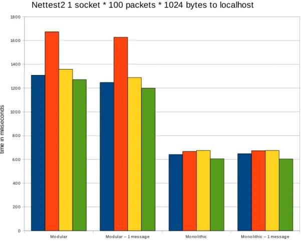
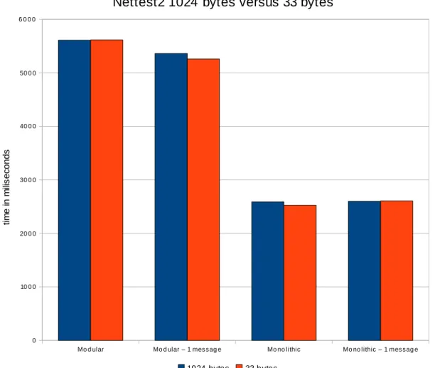
5 Evaluation 62 5.1 Nettest2 – data transfer performance . . . 63
5.2 Nettest1 – the overall performance . . . 67
5.3 Ping – ICMP echo performance . . . 69
5.4 Conclusion . . . 70 6 Other architectures 72 6.1 BSD . . . 72 6.2 Linux . . . 73 6.3 Windows . . . 74 6.4 Minix . . . 74 7 Conclusion 76 8 Terms and abbreviations 78 Bibliography 81 A Test results 85 B UML diagrams 88 B.1 Networking stack overview . . . 88
B.2 Module parts interaction . . . 90
B.3 Network interface initialization . . . 92
Chapter 1
Introduction
1.1
Motivation
In this work we analyze, compare, design and implement a networking stack which is an operating system’s subsystem connecting computers into networks. Although computer networks are in massive use these days there is no variability in reference implementations. Most of them are monolithic, having all the networking function-ality bundled in one large module, although the stack is internally layered. The target implementation introduces modular architecture into the networking stack. This means building the stack up from smaller modules where each module encap-sulates and provides one area of functionality, a protocol for example. They will be separate server modules each running as one task in the target operating system 1
. The stack is intended to be integrated to HelenOS, a microkernel operating system being developed at the Faculty of Mathematics and Physics, Charles University in Prague. The microkernel design and philosophy are briefly described as well as its re-quirements for additional modules’ architecture. The result of this thesis makes effort to become a modular TCP/IP networking stack proof–of–concept implementation.
1.1.1
History
The history of computer networks began in late October 1969 when the ARPANET project was born [25]. Before that time computers were isolated individuals. Since that time they are able to communicate with each other.
The ISO/OSI model was developed to standardize computer communication and is the first and most comprehensive networking model. It defines seven layers of functionality and abstraction. Unfortunately the model does not contain concrete protocols and the applicants did not have anything to follow. Another problem was its megalomaniac attitude. The model tries to solve almost all possible questions and uses of interconnected computers. Therefore it was far to complex to implement and spread protocols respecting it. Furthermore, the applicants had to pay a significant amount of money just to obtain the detailed model specification.
1
However, a different approach succeeded, the TCP/IP model. The model was based on simple and concrete protocols which were used to build up what was really needed. Its bottom–up approach led to its current world domination. This protocol family is called the TCP/IP protocol suite where the IP stands for the inter–network protocol and is the base protocol of the suite. It works on the principle of the best effort, the protocol tries to do its best to deliver data from one computer to another. The word “try” is the key as nothing is guaranteed. On the other hand TCP is probably the most used protocol on top of the IP protocol, it offers reliable connection between two computers. The TCP/IP suite contains many protocols covering most aspects of computer communication. Most of attention of this work will be drawn to this suite.
The protocols and design concepts are published as numbered RFCs which are public and rather technical documents covering usually only one topic, a protocol for instance. There is an RFC for each protocol in the suite, however, some protocols are extended in many RFCs. For example, there is one base RFC of the TCP protocol but hundreds of RFCs extending or altering its functionality in any way. RFCs do not become obsolete too often, they are usually updated or extended. The actual base RFCs of the TCP/IP suite come from early 1980s.
1.1.2
Implementation
As it was mentioned before, the TCP/IP protocol suite is extensively used. Com-puters usually do not have any other option how to connect themselves into current computer networks. One of the goals of this thesis was to develop a modular TCP/IP stack for a microkernel operating system HelenOS.
Porting an existing stack was also an option. It would have brought in many more features in exchange to the clean modular design as mentioned before. Some HelenOS-specific workarounds would have also looked odd in the system as a whole. Therefore a new implementation is introduced. It is designed from scratch and based only on the relevant RFCs. The modular design and inter–process communi-cation of the microkernel system are respected, of course. A modular and extensible architecture which seems to the author to be trusty to its purpose, as this archi-tecture complies with the overall archiarchi-tecture of the target microkernel system. The TCP/IP protocol suite is very well described and documented in RFCs and almost no other resources are needed.
1.2
Goals
This work follows a few goals. The main goal was a networking stack implementa-tion respecting the microkernel design of the target operating system. This emerged from the fact that the target HelenOS operating system did not have a network-ing stack. A new concept was to be thought up and designed. The networknetwork-ing stack moves HelenOS to the next level. It brings the possibility to communicate with other computers and systems.
The second goal is connected to the first one. This implementation might be-come, with a bit of luck, the reference implementation of a modular TCP/IP stack. Many believe that microkernel operating systems will have bright future and modu-lar architecture is the right way to go. Probably the most famous propagator of the microkernel design is Andrew Tanenbaum, an author of many publications about operating systems [27] and the microkernel operating system Minix. There are many advantages and disadvantages, attitudes and reasons for and against both the mono-lithic and microkernel operating systems 2
. Most often mentioned disadvantages of the microkernel design are inefficiency and insufficient flexibility. Both are explained and at least partly invalidated in the work of Jochen Liedtke [9].
There is also a research capacity to compare the modular stack implementation overhead to the monolithic approach. For this purpose the compilation into many small modules or one large module is designed and supported. We will measure and analyze differences between these two approaches.
1.3
Structure of the thesis
Here is a description of the master thesis structure and content of single sections:
Chapter 2 An introduction to the context of the work, the networking stack model and HelenOS.
Chapter 3 A summary of the modular architecture requirements with the proposed networking stack design. It includes detailed networking model layers, analysis and proposed modules’ description.
Chapter 4 A discussion about implementation decisions and problems.
Chapter 5 Architecture evaluation and comparison results.
Chapter 6 A few other networking stack implementations.
Chapter 7 A conclusion of the thesis.
1.3.1
Style conventions
The text follows a few style conventions:
• File and directory names are printed as source file.c.
• All referenced header and source files are located in the HelenOS source sub directory uspace/srv/net/ if not stated otherwise.
• Inter–process message names are printed asMODULE MESSAGE (argument).
• Code samples are printed in blocks 2
command;
function_call(argument);
• Constants and functions in the text are printed as ‘‘constant’’ and func-tion(argument)respectively.
Chapter 2
Context of the thesis
2.1
Networking stack models
The networking stack can be divided into a few layers. Each of them represents an abstraction for a particular functionality. The ISO/OSI model [31] defines seven layers whereas the TCP/IP stack defines only four or five [26]. The TCP/IP stack layer count varies sometimes because the bottommost layer may be split into two. Although this work focuses on the TCP/IP stack the ISO/OSI model should be mentioned first as it is more general. Its concept uses seven layers. Each layer uses the layer underneath and provides some functionality to the upper one. Except some rare exceptions layers should not traverse more than one level1
. The layer abstraction is that layers of the same level but on different hosts communicate with each other using lower layers transparently. A short description of the ISO/OSI layers follows and their scheme is in the Figure 2.1. The TCP/IP stack is described in detail the Section 3.2.
Physical layer
The bottommost is a physical layer. This layer transfers the smallest portions of data between network interfaces. Namely zeros and ones using electrical or optical impulses etc. Not only two network interfaces can be aware of the communication. Wireless networks are the best example that every network interface can hear the communication. Data unit being transferred by this layer is a bit. Some devices are capable to transfer more bits at once. In the sense of more bits at once, without any further knowledge about the data. This layer is about the transport medium, wires, air etc. and the transport perception.
Data link layer
The next layer is a data link layer. Whole data blocks are transferred between network interfaces. The source host directs the data block using the destination host’s address. The addresses are physical, usually assigned by network interface manufacturers. The
1
Figure 2.1: ISO/OSI Layers, the colors are assigned to the layers here and entities in other figures will preserve the colors of their parent layers.
data blocks are called frames. The network interfaces are the main business of this layer.
Network layer
The third layer is the network layer. It provides logical addressing and routing of data blocks. The data blocks, called packets, are logically routed through networks by this layer. This layer makes a computer network allowing indirectly connected computers to communicate. The lower layers make connections only between computers on the same transport medium.
Transport layer
A transport layer is the next above. This layer provides a transparent data flow be-tween two hosts. It can also provide reliable, flow and error controlled data transfers.
Session layer
The fifth is a session layer. It maintains logical connections between distant host applications. The logical connections allow the host to handle many networking ap-plications at the same time.
Presentation layer
There is also a data presentation layer. Transferred data have to be interpreted in the same way on both communicating sides. There can be highly different devices on each end of the connection. Therefore some standardization or pre–transport negotiation is necessary. A network byte order is the best example. The big–endian byte order 2
is used in the networking.
Application layer
The last layer is an interface for applications willing to use the networking stack. It offers host identification, connection establishment and data flow to the end appli-cations.
2.2
HelenOS specific design
In this section we describe the target system of the networking stack. HelenOS is under development of a research group at the Faculty of Mathematics and Physics, Charles University in Prague. It follows the microkernel design [8].
2.2.1
Kernel code
In operating systems there are two types of code execution, the kernel or privileged mode and the userspace or normal mode. Hosted applications run in the user space mode. The kernel code runs in a privileged mode. This mode allows access to all hardware, whole available memory including other tasks’ memory and all parts of the operating system as well. Therefore any bug in the kernel mode may lead to system instability, data loss or even hang ups.
The smaller the code is the easier it is to double or triple check it. While studying the microkernel design, an interesting observation was made, that the kernel code can be really minimal [27]. The microkernel design attempts to minimize the kernel code and modularize the system as a whole. The kernel code needs to handle hardware interrupts, host applications and provide hardware access to drivers. HelenOS follows the thought that only really necessary parts should run in the privileged mode.
2.2.2
Modularity
As the microkernel design runs little code in the privileged mode it is easier to run more stable. In addition some operating system tasks do not have to run in the privileged mode at all. Many drivers or abstraction layers function well even when placed into the user space. The possible inconsistency due to code defects stays local in the task itself if it runs in the user space. The kernel basically gives no other option. Therefore much of the standard operating system functionality is broken into small pieces running in the user space. Such pieces can be called modules. They
2
offer services to other modules so the overall architecture can be thought of as the service oriented architecture.
Furthermore the modular design may be used to reduce the overall complexity and ease development. The system is broken into functional components with defined interfaces [6]. The inner implementation is encapsulated and other components use it as a black box. The overall functionality is then built up from these components. Another possible extension to the current view of an operating system is the pos-sibility to check and restart defect modules. Either by polling the modules whether they are operational or by check–pointing their state.
2.2.3
Inter–process communication
Tasks communicate with each other through open connections using inter–process communication. The standard message passing mechanism is used. The sending task passes a message and can wait for a reply. The receiving task picks up the message and processes it replying the answer. Standard messages can have up to five integer arguments and up to five integer return values. The term “phone” is used in HelenOS for the task’s identifier of an open connection.
HelenOS provides an asynchronous library which maintains these connections and creates a fibril for each of them. Fibrils are the smallest points of execution in the user space. They are like threads in a main thread. Each connection fibril processes messages only of its connection. This leads to parallelism where there can be many messages processed at a time. The client connections are isolated and do not interfere with each other.
A memory block can be also copied between two tasks. This is useful for large data blocks. The memory block is copied if the tasks agree. The kernel does the job in this case.
The last possibility is to share memory blocks. The kernel maps the memory block into the address space of the target task. So both tasks are able to use the shared memory. Great care has to be taken and the memory access needs to be synchronized or standardized.
2.3
Qemu
emulator
As it is a bit hard to develop an operating system on a real hardware a simulator was used. A simulator gives the pleasure to develop test and debug the system in an efficient way. There is no need to dedicate a whole computer to run the system. Neither to transfer the built binaries to be able to execute them. Qemu is run on a host operating system and runs a guest operating system as if it was a standalone computer.
Furthermore, Qemu has a simple network interface. It emulates, among others, an ISA NE2000 network interface. ISA cards have the nice feature that the device IO port has to be statically set. This is the memory address used to communicate
with the device. Device registers are mapped there and the device is controlled by reading and writing them.
2.4
N. E. T.
In order to test and debug a networking stack a universal networking application is highly recommended. The stack itself contains functions and their counterparts which can be tested together. However, this would not reveal possible design mistakes, only programmatic. For example the checksum computation and check can function well together but it might be a different implementation than the protocol actually uses. Therefore an external application using another networking stack implementation is better as it tests these functions with their external counterparts. This should reveal both programmatic and design mistakes.
This application was developed as a testing tool of networking communication a few years before this work began. It is a modest application capable of communication using the lowest protocols, namely UDP and TCP. It is designed to provide useful networking communication information of the local and remote computers. The basic application features are:
• Sending and receiving packets of the TCP and UDP protocols on various ports as both the client and the server,
• Listening for connections,
• Ping and trace,
• Active ports enumeration,
• Getting host information including addresses,
• Getting protocol capabilities, configuration and information,
• Logging all printed information into a file, and
• GUI.
Despite the fact that this simple functionality is sufficient for the networking stack testing, the main feature is that the application allows users to define their own protocols. The whole process starting by a used protocol, connecting sequence, confirmation data, statuses and disconnecting sequence may be defined.
Chapter 3
Networking stack design
3.1
New networking stack
For the microkernel HelenOS a completely new networking stack was designed. The detailed description of requirements, architecture, support structures and modules follows.
3.1.1
Extent of the implementation
The networking stack was intended to implement current basic standards of the TCP/IP Stack. The standards are described in the form of RFC documents. The relevant RFCs are mentioned where appropriate. All the additional features of the TCP/IP Stack are far beyond the scope of this work. There are hundreds of ex-tensions, alterations or concretions on top of the core design. Only the minimalistic functionality allowing the stack to function was to be implemented. The detailed functional rules are enumerated in later sections closer to their topics. The imple-mentation goals were:
Initialize and use a real network interface network interface recognition, con-figuration, initialization and shutdown, sending and receiving packets, fault and state reception,
Support for more than one network interface advanced modular and depen-dency design, IP routing tables,
Implement the TCP/IP Stack IP, ARP, ICMP, UDP and TCP protocol mod-ules,
Implement the BSD socket interface for applications a socket application li-brary providing connecting and sending and receiving data functionality, and
Demonstrative applications ping, echo and similar applications.
The standardized TCP/IP Stack implementation allows the stack to coexist in most of the current networks whereas the standardized BSD socket interface eases porting of networking applications.
As HelenOS is written in the C language and it is an operating system with its own libc library, there are not many support structures. At least a basic ob-ject oriented approach is achieved by using structures as data classes and sets of functions manipulating them as methods. Implementation of the support of C++ in HelenOS would involve implementation of the C++ library. RTTI, inheritance, virtual methods, STL and integration with IPC would increase the scope of the thesis dramatically. Without this features there wouldn’t be any additional benefits compared to C. So the networking stack is written in C.
3.1.2
Architecture
For the stack development two approaches are possible. One monolithic–like module and separate device drivers and on the other side a fully modular architecture can be used.
The monolithic–like module and separate device drivers have one big advantage – there is no internal inter–process communication at all. There are only normal function calls internally. The union of functional modules offers also the possibility to keep shared data on one address in the address space which decreases resource consumption. The performance is probably the most obvious reason to use this de-sign. Nevertheless, there are disadvantages as well. Parts of this system are physically bound to each other. These parts correspond to functional modules in the meaning of reference model layers. Programmers are allowed to develop a bit fuzzy design with mixed global data structures and some possibly dirty workarounds and bypasses between functional modules. The stack is compact and extending it could involve internal changes. The stack cannot be divided easily either. Functional modules can depend on each other and function calls cannot be easily recognized and isolated. This is just a hypothesis if someone wants to exclude particular functionality. It can be, for example, an attempt to provide a special purpose networking stack based on a simplified one.
The fully modular architecture has every functional unit in a separate module. The modules communicate only using well defined interfaces. It needs a bit more detailed analysis of the modules’ cooperation. Also the common data structures have to be distributed to all concerned modules. This approach is preferred in order to demonstrate a functional modular stack running in a microkernel operating system. There is one important advantage – each functional module is physically isolated. The functional modules have well defined interfaces and could be fully replaced without the need to modify any other modules. New modules are free to connect to this interfaces and extend the stack. There is also well defined module dependency and modules can be excluded.
3.1.3
Modular architecture
In this section we describe the module concept in general. The networking stack is split into many small modules which reduces the overall complexity and encapsu-lates functionality. Each module represents an actual implementation of a particular
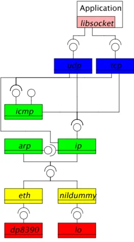
protocol or driver. For each networking layer there are several modules. Every mod-ule communicates only in its or the next bottom or up layer. The modmod-ules provide their functionality only to their neighbours and the upper layer. It complies with the networking stack models where at most one level should be traversed. An overview can be seen in the Figure 3.1. Usually, networking stacks are internally modular. The difference is that the proposed one will be modular globally.
Figure 3.1: Modular networking stack
On one hand the networking stack architecture is a bit complicated, but, on the other hand it complies with the modular design. There can be several network inter-faces controlled by their drivers. The TCP/IP stack does the routing and registers its receive points at the drivers. On the other end an application should not interact directly with the stack but rather through a standardized library. Applications use a networking library which provides an abstract socket interface masking the stack underneath. The stack itself contains many functional modules corresponding to the networking layers and protocols.
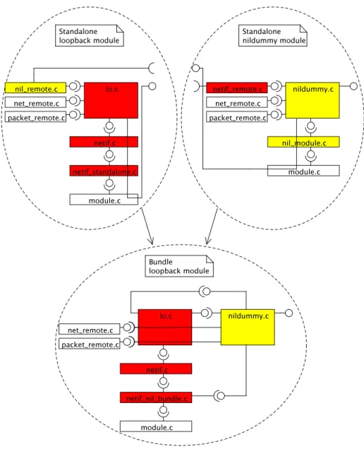
In the compile–time configuration of the proposed stack, either the modular or the monolithic architecture type can be chosen. This is supported with the consideration of the later demonstration and comparison of both the monolithic and the modular implementation.
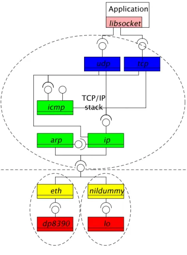
interface drivers have to be separated. That is due to the big number of driver families and a networking stack bundled with all of them would be really huge. Therefore the right division line of the monolithic implementation has to be drawn. The same problem is a layer up in the network interface layer as well. There are many network interface access protocols which are specific to the used network interface driver family. For example Ethernet, Token Ring, ATM, Point–to-Point Protocol etc. They cannot control all types of network interfaces and vice versa. This means that the present network interface implicates the driver module and the data link module. On top of that, the TCP/IP suite works abstracting from the fact how the data link layer works. So the division is set between the data link layer and the network layer and is depicted in the Figure 3.2.
Figure 3.2: Monolithic networking stack
We should consider hardware and application limitations as well. There has to be a network interface driver for each network interface family. The driver can be also capable of controlling multiple devices in order to avoid multiple instances of the same driver and unnecessary overhead. On the other hand a bug in the controlling of one of the devices can break the controlling of the others. Devices keep most of their configuration and state in their own data structures and allow drivers work with
them through memory address spaces. Therefore the driver itself is almost stateless and it can handle more devices at a time without any disruption. There can be several network interfaces controlled by their drivers in the system at a time. Either using the same or several drivers1
. The TCP/IP stack does the routing and registers its receive points at the drivers.
The applications willing to use the networking capabilities of the system use a li-brary. The socket interface was developed to unify the abstraction of the networking stack. The applications using this interface can be ported to and function with other networking stack using the same interface. The library is only a wrapper providing the networking interface to applications.
Inter–process communication
In order to successfully orchestrate modules their cooperation should be carefully an-alyzed. There is an interface designed for each of the modules to publish its function-ality. There are layer– and module–specific interfaces. The layer interface is a general layer functionality whereas the module specific serves its special purpose. This allows layer abstraction where more similar modules can work in the same layer and other layer modules could use either of them. The network and network interface layer modules are the best example as we discussed them in the context of the monolithic division line. Only known and almost hardwired connections would be possible oth-erwise. The driver just sends packets and state notification to its network interface layer buddy but the TCP protocol has to distinguish between the IP and the ICMP protocol. A module usually implements its layer interface.
Server modules should be able to serve many connections as they offer their services to others. They are also clients of other server modules. It would be very inefficient if a module had to wait until another message gets processed. Some com-plex messages can take a long time to complete. They can involve several other IPC queries. Therefore the networking stack should work in parallel.
On the other hand the parallelism lays stress on global data structures in the server modules. The global data have to be protected against multiple fibrils pro-cessing messages. Most of the messages can be easily divided into two groups. Some does not change the global data, but they need to read them. For example if a packet gets passed through a module, only the actual setup is read, the packet is processed and passed to another module. Other messages change the module setup. For exam-ple the initialization of a new protocol or device involves reading configuration or setting up routing tables. The most adequate synchronization primitives are there-fore the read–write locks 2
. The rest of the messages can change the module setup on some conditions. They either swap the lock from reading to writing or lock it for writing. It depends on the likelihood of the writing process.
1
An Ethernet router contains many instances of the same network interface to allow many hosts to connect whereas a host can contain an Ethernet and WiFi network interfaces.
2
3.1.4
Packet management system
A packet in the sense of the networking stack is a block of formatted data. Networking stack processes packets and have to pass them between its modules. The memory block can be passed between modules via inter–process communication messages. Unfortunately, this would be highly ineffective as the packet data would get copied due to the task isolation. In the monolithic–like stack this would happen only at the top and at the bottom of the stack, from client applications and to network interfaces. If the stack is to be modular the inter–process communication performance is the cutting edge. The fastest way is to transparently share the packet as an address space page. So only packet identifiers get transferred. This rapidly increases the stack performance. There is no internal copying of data. They are copied only at the top and at the bottom of the stack as in the monolithic case. However, the shared packet memory block has to be distributed between the concerned modules first. Strict rules need to be stated and obeyed as well:
1. Only modules in the networking stack and network interface drivers may have access to packets,
2. Only provided packet manipulation functions must be used,
3. A module processes a packet only if it is the exclusive owner of the packet:
• The module becomes the exclusive owner if
– requests a new packet, or
– is asked to process the packet
• The module is the exclusive owner until
– passes the packet to another module, or
– releases the packet.
The packet structure itself should never be accessed directly. Packet manipulation functions are provided in a form of a library described in the Section 4.1.2.
Architecture
The networking stack packet management system consists of a packet server and a library. The packet server needs to be implemented by one well–known module in the stack. Its job is to manage packets. All packets in the stack are in possession of this module. The packet library should be part of each module willing to process packets. It provides packet mappings into the task’s address space and communicates with the packet server. Other modules can request a new packet and the packet server creates a new one or reuses an old one. Until the packet is released again it cannot be reused by the server. Any stack module can release the packet, not only the requesting one. If a module is asked to process a packet it uses the packet library to get the packet. If the packet has already been used, the library finds the packet mapping to the task’s address space. If not, the library requests the packet from
the packet server. The packet server shares the packet as a memory block with the requesting task and the library returns the newly shared packet.
Packet processing
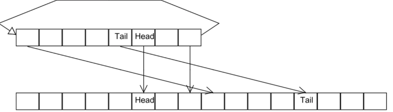
There are two directions of packet processing. A network interface driver uses clean or new packet to provide the received data to the networking stack. The transferred application data are incrementally unwrapped on their way through all the modules. The topmost layer uses clean or new packets to send data through the networking stack. The transferred application data are incrementally wrapped on their way through all the modules. The processing time is crucial, so we would like to avoid data copying as much as possible. There has to be some infrastructure developed around the packet processing. As we mentioned before, each module wraps or unwraps the passed data. Each module knows how to do its job and does not have to be aware of the others. The idea is to keep the application data on one place during the whole process. The modules then incrementally just cut or prefix and/or suffix their specific wrappings.
Another option would be a list of succeeding memory blocks 3
. Each module just prefix or suffix its wrapping as another memory block. This increases the complexity as one packet is split into—possibly many—small pieces. For example a checksum computation of such a packet have to jump from one piece to another. Furthermore this is not a universal solution. All modules have to be able to process such block lists. However, some network interfaces are able to transfer only continuous block of data 4
. The blocks need to be serialized for them first. Unfortunately, this would be another data copying decreasing performance.
The packet size is loosely limited only by the MTU setting. However, the IP protocol, for instance, allows content only up to 65 535 octets long. The MTU may be specific for each device, network or protocol used. New outgoing packets have to be created with the MTU size taken into account. The IP protocol supports packet fragmentation for “small packet” networks. The upper protocols do not have to respect this setting as it is transparent for them. However, they could decrease load of their underlying IP module by doing so.
3.2
Networking stack modules
The HelenOS networking stack is described from the bottom layer up according to the TCP/IP model. The relevant ISO/OSI layers are referenced where appropriate. Each module description is followed by its public interface. Module interactions are described and some even depicted in UML diagrams. For a visual representation of the whole stack in an UML diagram see the appendix Section B.1. A central configuration module is described first.
3
The technology of transferring and receiving succeeding blocks of data as one frame is called scatter–gather or vectored input–output.
4
They can use only a simple DMA access to read a continues block without any other option, for example.
3.2.1
Central configuration module -
net
The central module is the heart of the networking stack. This module implements the packet server, reads the networking configuration and starts required service modules. The configuration consists of the general networking stack and network interface specific parts. The stack configuration is textual. Numeric settings are parsed as integers, switches starting with ′y′ as enabled. The general configuration specifies:
MTU The default maximum transmission unit. Set to ‘‘1500’’.
ICMP ERROR REPORTING The Internet Control Message Protocol error generation and reporting switch. Set to‘‘yes’’.
ICMP ECHO REPLYING The Internet Control Message Protocol echo reply generation and reporting (ping) switch. Set to‘‘yes’’.
IPV The default Internet Protocol version. Set to‘‘4’’.
IP ROUTING The general IP routing switch. Set to ‘‘no’’.
UDP CHECKSUM COMPUTING The User Datagram Protocol optional out-going traffic checksum computation switch. Set to‘‘yes’’.
UDP AUTOBINDING The User Datagram Protocol optional automatic bind on send if not bound switch. Set to ‘‘yes’’.
The network specific configuration contains:
NAME The network interface name.
NETIF The network interface driver module name.
NIL The network interface layer module name.
IL The inter–network layer module name.
The generic stack configuration can be overridden by the network interface specific. Any other configuration is also tracked so stack modules are free to add their specific settings. Module specific settings are mentioned at each of them. Modules can query thenetmodule about a general or specific setting by its label. If the network interface specific setting is not found the general stack configuration is searched then.
This module starts needed modules of the stack and initializes network interfaces. The networking stack startup is described later in the Section 4.1.4.
net interface
The net module offers the following interface:
• net connect module(net service) function and its backing
IPC M CONNECT ME TO message to connect to the net module returning the connection phone.
• net free settings(configuration, data) to release the returned setting values. Should be used in conjunction with either general or network interface spe-cific configuration request. If used in a bundle module, no memory is freed as the values buffer is empty.
• net get device conf req(net phone, device id, configuration, count, data);
NET NET GET DEVICE CONFto read the network interface specific config-uration. The requested setting labels are transferred as measured string field and values in the opposite way. If used in a bundle module the values are not copied to the buffer and must not be freed.
• net get conf req(net phone, configuration, count, data);
NET NET GET CONF to read the general configuration. Similar to the pre-vious one.
3.2.2
Network interface drivers
A network interface, often referred as a network card, is the most important part of the stack. Roughly said, it is used to communicate with the outside world. Therefore all the outgoing and incoming traffic goes through the network interface. This is the bottommost layer in the ISO/OSI model, the physical layer.
There are a few basic capabilities of a network interface driver which need to be implemented. The most important ones are sending and receiving packets. The driver should be able to start and stop the device and accept a configuration from the networking stack. The devices can be present and configured but temporary disabled if desired. Controlling multiple devices is an optional feature.
Drivers can also provide some diagnostics and statistics for the system which should be updated appropriately.
The driver should be capable of:
• Discovering a device,
• Configuring a device,
• Starting a device,
• Stopping a device,
• Sending a packet,
• Providing a received packet,
• Returning device usage statistics, and
A network interface layer module can register itself as the packet supplier and con-sumer of the device. Incoming packets are delivered to that module asynchronously. The network interface layer could also poll the driver frequently to obtain received packets. This option is not used as it increases overhead and is inefficient when there are no packets. On top of that if the driver is not queried often enough, the received packets can fill its buffers and may be discarded.
The driver can use device specific hardware settings such as input/output address space and IRQ. The driver then registers and handles IRQ events. Network interface drivers obtain the IRQ numbers and IO port addresses at the device initialization. Device configuration entries IRQ and IO, respectively, are forwarded to the driver.
Network interface driver interface
The network interface driver modules offer the following interface:
• netif bind service(netif service, device id, calling service, receiving callback)
function and its backing IPC M CONNECT TO ME message to register itself as the received packets consumer.
• netif get addr req(netif phone, device id, address, data);
NET NETIF GET ADDR to read the network interface hardware address.
• netif probe req(netif phone, device id, IRQ, io);NET NETIF PROBEto probe if there is a device at the specified memory address using the specified IRQ.
• netif send msq(netif phone, device id, packet, sender service);
NET NETIF SEND to send the packet via the specified device.
• netif start req(netif phone, device id); NET NETIF SEND to start the speci-fied device.
• netif stats req(netif phone, device id, stats); NET NETIF STATS to read the specified device’s usage statistics.
• netif stop req(netif phone, device id);NET NETIF STOPto stop the specified device.
Loopback network interface - lo
The loopback network interface is a special device which returns all outgoing packets back as incoming ones. The motivation for this device is to enable network commu-nication between both server and client applications running on the same host. The applications are connected as being remote, however, the communication goes just through the local networking stack. There are no problems with carrier, protocols and formats and “the other side” is always reachable5
. There is also no need of a real network interface device.
5
The lo driver is designed as a standalone module with capabilities of a regular device driver. The driver itself creates a virtual device and returns all outgoing packets as incoming incrementing the usage statistics accordingly. This is due to the requirement of usage statistics and transparent driver interface. In the extreme case only the user knows that this network interface is the loopback. Therefore the loopback does not need any special configuration.
NE2000 network interface driver - dp8390
The main goal of the networking stack is to connect the computer to a computer network. A real network interface enabling us to connect to the outside world is needed. There are hundreds of network interfaces and supporting them would be a long term run. For the successful networking stack demonstration one is enough. A NE2000 network interface family was chosen6
. A lot of its clones 7
exists which is one of the main reasons. Another one is its simplicity. An ISA version of this network interface resides in the address space on one of the specified locations.
Qemuemulates the NE2000 network interface as well. So the decision was made to support this one. A more recent chip DP8390Dby National Semiconductor actually. This chip is well documented in the data sheet [7] on the manufacturer’s website.
3.2.3
Network interface layer
The network interface layer is the data link layer in the ISO/OSI model. This layer transfers whole blocks of data between two network interfaces, possibly on different hosts. The network interface layer module is specific for the type of network the computer is connected to.
There can be many network interface layer modules implementing various types of networks such as Ethernet, TokenRing etc. The network type is partly determined by the used network interface. Not all network interfaces support all types of networks. The NE2000 supports only the Ethernet.
The interface for the upper layers is transparent of the network type. So the bundle build is supported only with drivers, not the upper stack.
The network interface layer module can also distribute packets between the upper layer modules according to the inner frame protocol. There can be more than one upper layer module using this one for sending and receiving packets. The upper service module has to register itself and the network interface layer module can take into account the packet distribution. Packets are passed one by one. Concrete rules are module specific and will be described in the later example of IEEE 802.3.
Network interface layer interface
The network interface layer modules offer the following interface: 6
This is a product line started in early 1990s originally by Novell. It became de facto a standard because it spread widely thanks to its low price.
7
Clone is a compatible network interface, it behaves and can be controlled in a very similar way.
• For the upper stack:
– nil bind service(nil service, device id, calling service, receiving callback)
function and its backing IPC M CONNECT TO ME message to register itself as the received packets consumer, there can be more consumers per device based on the stated service.
– nil device req(nil phone, device id, mtu, netif service);
NET NIL DEVICEto register a device and its driver.
– nil get addr req(nil phone, device id, address, data);NET NIL ADDR to read a network interface hardware address.
– nil get broadcast addr req(nil phone, device id, address, data);
NET NIL BROADCAST ADDR to read a network interface broadcast address.
– nil packet size req(nil phone, device id, addr len, prefix, content suffix);
NET NIL PACKET SPACE to read maximum packet dimensions, min-imal address length, prefix and suffix and maximum content length in bytes.
– nil send msq(nil phone, device id, packet, sender service);
NET NIL SEND to send a packet (queue) via the specified device.
• For drivers:
– nil device state msg(nil phone, device id, state);
NET NIL DEVICE STATEto process the device state change.
– nil received msg(nil phone, device id, packet, target service);
NET NIL RECEIVED to process the received packet.
Dummy network interface layer - nildummy
There is one special network interface layer module, a dummy one. It is used just to bridge communication between a network interface driver and the upper stack. One module is allowed to register itself as a consumer of received packets. Only devices registered with the nildummy module are available.
The purpose of this module is to keep the layer division. A driver does not have to process network interface layer messages nor sends them to an upper inter–network layer module. The messages are translated appropriately. Furthermore, the invariant that layers should not traverse more than one level is kept as well.
The most obvious network interface driver lying underneath is the loopback one where no added functionality is needed.
IEEE 802.3 - eth
One of the most widely used network types is the, informally called, Ethernet. The technology is standardized asIEEE 802.3. The history of the original Ethernet begun at XEROX PARC in 1976 [12]. The name comes from an ether, a fluid allowing
transfer of electromagnetic energy as it was thought at the end of the 19th
century. The name Ethernet was released to the public domain later. It coexists asEthernet II
or DIX Ethernet 8
now. IEEE 802.3 is a bit younger technology describing almost the same. IEEE 802.3 covers data transfer between two network interfaces at the same medium, for example connected by a wire. There are a few variants according to the medium, transport direction and speed used.
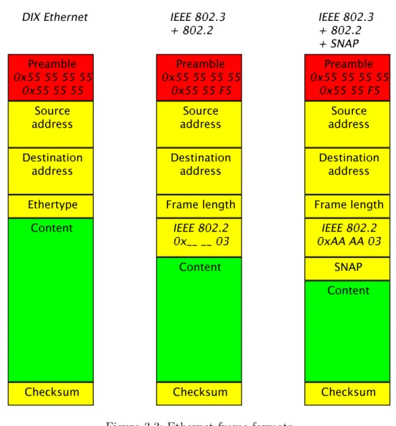
Figure 3.3: Ethernet frame formats
There can be also more network interfaces attached to the same medium and therefore addressing of data plays its role. Devices are assigned MAC addresses by their manufacturers. This addresses should be globally unique. They are hardwired but some devices allow users to change them. The network interface should receive only data labelled with its assigned MAC address 9
. There exists a standardized 8
DIX stands for the founding companies Digital, Intel and Xerox. 9
There are also network interface operation modes allowing to receive all frames or respecting an address pattern.
broadcast address to send data to all listening network interfaces.
The frame format differences are described in this paragraph and depicted in the Figure 3.3. Both DIX Ethernet and IEEE 802.3 use almost the same header preceding the actual frame data. A frame type or ethertype header field in DIX is used as a frame length inIEEE 802.3. The basic frame type was used to distinguish the inner frame protocol, the higher protocol transferring its own data inside the Ethernet frame.
On the other hand the frame length offers better consistency check. Furthermore, the length is important as there is a minimum length limited. The frame content has to be at least 46 bytes long. It is padded with zeros if shorter. The frame length reveals such a padding whereas the frame type does not and the inner protocol or protocols have to find it out by themselves.
The IEEE 802.3 does support frame type as well, but in an additional IEEE 802.2 header. The usual frame types are all numbers higher than 1536 (0x0600). So IEEE decided to restrict frame type to be higher than 1536 and frames are allowed at most 1500 bytes of data. The coexistence of this two frame formats is explicitly possible. Frames can be easily recognized by the frame type/length header field.
TheIEEE 802.3header can be further extended byIEEE 802.2andSNAP head-ers. The IEEE 802.2appends the destination and source service access point iden-tifiers to the IEEE 802.3 header. This service access points are equivalents to the frame types. TheIEEE 802.2 header format is in the Figure 3.4. The last byte—the
Figure 3.4: IEEE 802.2header, each field of one byte.
control one—can be used in many ways. For upper layers encapsulation only the Unordered Information frame type of the value 0x03 is used.
When the service access points were designed a one byte field looked long enough. However, it was quickly almost exhausted. SNAP—represented in the Figure 3.5—is the most recent approach reintroducing two byte frame types on top ofIEEE 802.2. Both service access points are set to 0xAA and the original frame type is attached.
Figure 3.5:SNAP header, organization or protocol code of three bytes, ethertype of two bytes.
The RFC 948 [28] defines transfer of higher protocol IP in Ethernet frames. The above mentioned frame types are supported. This definition can be also generalized for all higher protocols.
Ethernet also introduces a consistency check. At the end of each frame a checksum is carried. Ethernet checksum is based on CRC32. To be precise, a bitwise comple-ment of CRC32 with a seed of all ones is transferred in the network byte order.This checksum is used to identify faulty transfers.
The ethmodule implements all of the above mentioned frame formats. A modern network interface should be able to receive frames of all formats and should generate only one frame format [16]. So IEEE 802.3 with SNAP is the default despite the fact that the very first network interface (DP8390 in Qemu) understands only the
DIX Ethernet 10
. This emerged in a device configuration setting ETH MODE of the
‘‘DIX’’, ‘‘8023 2 LSAP’’ or ‘‘8023 2 SNAP’’ value. The DP8390 network inter-face also handles frame preamble and checksum computation and check on its own. Therefore another device configuration setting is used to enable explicit frame pream-ble and checksum computation and checks. This switch is labelled ETH DUMMY
and is disabled by default.
3.2.4
Inter–network layer
Going a layer up, we traverse the conceptional division line. We are getting into the domain of the TCP/IP stack core protocols. The first layer supplies the ISO/OSI network layer.
This layer enables logical networking and routing. Packets being transferred be-tween hosts can traverse multiple network interfaces or even logical networks. The inter–network layer allows hosts to identify available routes and other hosts’ presence. A host can have more network interfaces and this layer routes packets to ap-propriate ones. The host with more network interfaces can be also connecting more logical networks. They are so–called multihomed hosts and can function as gateways between the networks.
Inter–network layer interface
There is a standardized interface used by lower layers to communicate with the inter–network layer modules:
• il device state msg(il phone, device id, state, target service) function and its backingNET IL DEVICE STATE message to process the device state change.
• il received msg(il phone, device id, packet, target service);
NET IL RECEIVED to process the received packet.
• il mtu changed msg(il phone, device id, mtu, target service);
NET IL MTU CHANGED to process the device MTU change.
On the other side no standardized interface exists for networking stack modules as they are aware of whom they are sending messages to. The TCP/IP Stack is designed
10
In fact this is one of two proposed transfer methods for the IP protocol over the Ethernet in the RFC 948 [28].
to function with a concrete protocol in the inter–network layer, the IP protocol. So the upper layer modules do know exactly who is underneath.
Address Resolution Protocol - arp
As the TCP/IP stack communicates with hosts according to their logical IP ad-dresses, lower layers do not understand them and the addresses have to be translated. The ARP protocol provides this service. The protocol is defined in the RFC 826 [21]. It is a universal protocol translating addresses to and from many protocols.
If an address translation is not already known a discovery request packet is sent to all connected hosts. ARP uses a variable length packet where appropriate hardware and logical address spaces are allocated for both the source and the destination host 11
. The destination hardware address is unknown and left empty. The hardware broadcast address is used as the destination address of the packet so other hosts’ network interfaces receive the request.If the host recognizes its logical address a reply with all addresses filled is sent back to the request source.
ARP implementations cache translations for further use. If an error occurs— packets do not get delivered or the host unreachable notification is received—the cached translation should be cleared.
A timeout would be also an option. However, there is a bit of inefficiency. If a host is present, the timeout clears the mapping and the broadcast query needs to be send and replied. This puts unnecessary load to all connected hosts frequently. It can also lead to flooding in a big network. However, the timeout helps to discard unused entries and to propagate dynamic network changes.
On the other hand if a packet gets lost or an error is reported, the mapping is cleared and the packet can be resend. This involves the broadcast request as well, however, the caused load is unavoidable in order to recover from the error.
Although there is only the arp module present in the stack, some other can be added later. The particular ARP module can be specified via the device configuration
ARPsetting. This device specific setting is passed to the relevant inter–network layer module. That module should respect the ARP configuration and use the proposed ARP module.
ARP interface The address resolution protocol modules should offer the following interface:
• arp clean cache req(arp phone) function and its backing
NET ARP CLEAN CACHEmessage to clear whole cache.
• arp clear address req(arp phone, device id, protocol service, address);
NET ARP CLEAR ADDRESS to clear the device protocol address transla-tion.
11
In case of IP and Ethernet the logical address has four bytes whereas the hardware has six bytes.
• arp clear device req(arp phone, device id);NET ARP CLEAR DEVICE
to clear the device cache.
• arp connect module(arp service); IPC M CONNECT ME TO
to connect to the arp module returning the connection phone.
• arp device req(arp phone, device id, protocol service, netif service, address) NET ARP DEVICE message to register the arp module for the device at the driver and to save the requesting protocol logical address.
• arp task get id() returning the task identifier if called in the bundle module.
• arp translate req(arp phone, device id, protocol service, address, translation, data);NET ARP TRANSLATEto translate the protocol address to the hard-ware address.
Internet Protocol - ip
The central protocol of the suite is the Internet Protocol. The IP protocol version 4 is defined in the RFC 791 [18] by DARPA from 1981. This protocol provides best–effort packet transfers. It tries to do its best to deliver packets to other hosts.
The fourth version is the first widely deployed version. There is a newer IP ver-sion 6. This verver-sion introduces longer addresses, extended addressing and routing, mobility, and IPsec. Implementation of this version could be a topic of another mas-ter thesis. The still used and simpler version 4 is implemented in this one instead.
IP addressing Hosts are identified by their IP addresses. Each address falls into an IP network. The address prefix of certain length is the network. The IPv4 uses four byte addresses and networks are assigned by IANA. There are groups of networks with fixed number of bits where the very first few bits of an address determine the network group. The textual addresses are written as four decimal numbers separated by dots.
The four byte addresses might have been enough for the world—it is 4 294 967 296 addresses, more than 4 billions—but not the network groups. An organization willing to have all its computers in its own network has to request a network. The network is assigned from the smallest group the computer count fits in. As bits in the ad-dress cannot be divided, only sizes in multiples of two are available. The problem deferred by using two special networks 192.168.0.* and 10.*.*.*. Anyone may use these networks while not being directly connected to other networks, especially to the Internet. Such networks are local and can be connected to other networks using gateways.
Along with network groups there are also network masks. It is a bit more universal approach. The address is divided into a network address and a host identifier. The mask contains ones at the network address places and zeros at the host identifier, respectively. A network can be divided into smaller parts if the mask sets more bits. In order to communicate with others, a host has to maintain its routing table. The table contains entries where to send packets targeted to other hosts. Hosts of the
same network can be accessed (almost) directly but hosts of other networks not. The institution of multihomed gateways is introduced for the latter case. The host can be configured to send packets to other network using a gateway. The gateway forwards that packets further to the proper network or another gateway. The gateway routing can be set as a network and a netmask, where only the mask bits are compared to the target address. It can be less than the target network mask. Similar entries can be grouped together by shortening the mask. This is called the Classless Inter–Domain Routing.
Hardware address resolution Any ARP module can be configured for the hard-ware address resolution needs. The ipqueries the ARP module for IP address trans-lations then.
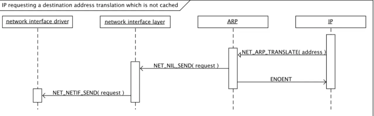
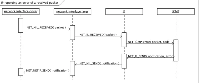
There was an option to ask the ARP to send the packet itself which would save one message in the inter–process dialogue. However, it would shift some IP functionality to ARP modules which would be against the modular architecture decided before. Therefore the address is requested, read and the packet is then sent. Please see Figures 3.6 and 3.7.
Figure 3.6: IP requesting a destination address translation which is not cached.
IP protocol The IP packet header consistency is verified by a checksum. Although this checksum is weaker than the CRC in the Ethernet Section 3.2.3 presented earlier, it is used in other core TCP/IP protocols as well. The RFC 791 [18] authors stated
...experimental evidence indicates it [the checksum] is adequate, but it is provisional and may be replaced by a CRC procedure, depending on further experience.
Nevertheless, the proposed checksum computation is still in use, 28 year later. This is partly because it is sufficient and partly because it has spread widely and any change would be very costly as many implementations already use that. Its RFC definition 12
seems hard to understand but the principle is in fact very simple. The packet header is divided into 2 byte blocks which are summed. The result is split into high and low two bytes and summed again until the high part is zero.
As some protocols are not obligated to compute the checksum and set it to zero a computed zero checksum has to be distinguishable. The computed zero is flipped into all ones.
On one hand there is problem of this checksum as it cannot recognize 2 byte blocks being swapped, but, on the other hand it allows partial checksum computation and, furthermore, in any order. This feature and more are presented in the RFC 1071 [4] with implementation examples to speed up the checksum computation.
ip module Theipmodule implements the IP protocol. The module supports more network interfaces and implements CIDR routing tables.
Based on the device configuration IP ROUTING switch it can serve as a router. The incoming traffic will be forwarded further if not targeted to the local host, the router. For security reasons only routers should enable this setting. An Internet attached host can serve as a gate to its inner local network otherwise, even if not intended to. Packets for the inner network sent from the outside network would be routed properly in.
The module also allows connection to the local host via a loopback network interface which should have the IP address 127.0.0.1. The default gateway for un-determined routing direction can be set as well. The IP protocol supports packet fragmentation if a packet does not meet the target network MTU.
In case of errors during packet processing, error notifications are generated using the ICMP protocol13
. Either if the network is unreachable, the host is unreachable, the checksum check fails or the time to live runs out. No additional notifications should be generated while processing error notifications.
Client modules register themselves at the ip module by their IP protocol iden-tifiers. Received packets are delivered according to these protocol ideniden-tifiers. The networking stack can be easily extended with other protocols on top of the IP pro-tocol.
12
The checksum computation and optimization techniques are described in the RFC 1071 [4] and its updates 1141 [10] and 1624 [22].
13
IP interface Theipmodule uses more device configuration settings along with the
ARP and the IP ROUTING. First and most important is the IP CONFIG denot-ing ‘‘static’’ address configuration. No other value is supported yet as the net-working stack contains only core protocols and further would be necessary, namely DHCP or at least BOOTP. For the static configuration the network interface address
IP ADDR, IP BROADCAST and IP GATEWAY addresses andIP NETMASKare read. They should be set to a textual IP addresses, ‘‘10.0.2.15’’ for example.
ip interface The ip module offers the following interface:
• ip add route req(ip phone, device id, address, netmask, gateway) function and its backingNET IP ADD ROUTEmessage to add a route entry for the device.
• ip bind service(ip service, protocol, calling service, receiving client connection, receiving callback); IPC M CONNECT TO ME to register itself as an upper protocol, either the callback or the client connection function is used according to the build architecture.
• ip connect module(ip service) to connect to the ip module returning the con-nection phone.
• ip device req(ip phone, device id, netif service); NET IL DEVICE to register a device and its driver.
• ip get route req(ip phone, protocol, destination, address length, device id, pseudo header, header length);NET IP GET ROUTE to get a destination di-rection and pseudo header for sending.
• ip packet size req(ip phone, device id, addr len, prefix, content suffix);
NET IL PACKET SPACE to read maximum packet dimensions, minimal ad-dress length, prefix and suffix and maximum content length in bytes.
• ip received error msg(ip phone, device id, packet, target service, error service);
NET IP RECEIVED ERROR to announce a received error notification.
• ip send msq(ip phone, device id, packet, sender service, error service);
NET IL SEND to send a packet (queue). A particular device can be specified. If the error service is set, no further errors are generated.
• ip set gateway req(ip phone, device id, gateway);NET IP SET GATEWAY to set the default gateway.
Internet Control Message Protocol - icmp
The ICMP protocol defined in the RFC 792 [19] is a support protocol for the TCP/IP suite protocols. It carries error notifications and diagnostic messages. If an error occurs an ICMP packet is created. It contains the beginning of the original packet starting with the original IP header.
ICMP packets are sent via IP and there is a protocol number assigned for the ICMP protocol as well. Therefore ICMP behaves in a similar way like upper protocols in the transport layer. Theicmpmodule registers at theipmodule and received ICMP packets are then delivered to the icmp. However, the ICMP protocol actually falls into the inter–network layer next to the IP protocol. It does not add extra logic as other protocols in the above layer.
The ICMP error reporting can be disabled by setting the global configuration
ICMP ERROR REPORTINGswitch to anything else than ‘‘yes’’.
The ICMP protocol offers more than just error notification. There is one highly demanded functionality, the echo. One host sends an echo request to another host and waits for a reply. If the other hosts is reached—and is not configured to block ICMP echo requests—the same packet is sent back as the echo reply. The packets contain sequence numbers to match the replies with the previous requests. The ICMP echo replying can be disabled by the global configurationICMP ECHO REPLYING
switch. A local application is allowed to connect to the icmp module and call the echo process.
The ICMP protocol client application can use the interface:
• icmp connect module(icmp service) function and its backing
IPC M CONNECT ME TO message to connect to theicmpmodule returning the connection phone.
• icmp echo msg(icmp phone, message size, timeout, ttl, tos, dont fragment, ad-dress, address length); NET ICMP ECHO to ping a host.
icmp interface The icmpmodule offers the following interface:
• icmp connect module(icmp service);IPC M CONNECT ME TO to connect to the icmp module returning the connection phone.
• icmp destination unreachable msg(icmp phone, code, mtu, packet);
NET ICMP DEST UNREACH to report the destination unreachable error.
• icmp parameter problem msg(icmp phone, code, pointer, packet);
NET ICMP PARAMETERPROB to report the parameter problem error.
• icmp source quench msg(icmp phone, packet);
NET ICMP SOURCE QUENCH to report the source quench error.
• icmp time exceeded msg(icmp phone, code, packet);
NET ICMP TIME EXCEEDED to report the time exceeded error.
3.2.5
Transport layer
Although the IP protocol offers host to host communication this is not enough. The next layer, the transport layer, enables more host connections to run parallel.