Resource Management in Virtualized
Data Center
by
Md Rabbani
A thesis
presented to the University of Waterloo in fulfillment of the
thesis requirement for the degree of Master of Mathematics
in
Computer Science
Waterloo, Ontario, Canada, 2014
c
Declaration
I hereby declare that I am the sole author of this thesis. This is a true copy of the thesis, including any required final revisions, as accepted by my examiners.
I understand that my thesis may be made electronically available to the public.
Abstract
As businesses are increasingly relying on the cloud to host their services, cloud providers are striving to offer guaranteed and highly-available resources. To achieve this goal, recent proposals have advocated to offer both computing and networking resources in the form of Virtual Data Centers (VDCs). However, to offer VDCs, cloud providers have to overcome several technical challenges. In this thesis, we focus on two key challenges: (1) the VDC embedding problem: how to efficiently allocate resources to VDCs such that energy costs and bandwidth consumption are minimized, and (2) the availability-aware VDC embedding and backup provisioning problem which aims at allocating resources to VDCs with hard guarantees on their availability.
The first part of this thesis is primarily concerned with the first challenge. The goal of the VDC embedding problem is to allocate resources to VDCs while minimizing the bandwidth usage in the data center and maximizing the cloud provider’s revenue. Exist-ing proposals have focused only on the placement of VMs and ignored mappExist-ing of other types of resources like switches. Hence, we propose a new VDC embedding solution that explicitly considers the embedding of virtual switches in addition to virtual machines and communication links. Simulations show that our solution results in high acceptance rate of VDC requests, less bandwidth consumption in the data center network, and increased revenue for the cloud provider.
In the second part of this thesis, we study the availability-aware VDC embedding and backup provisioning problem. The goal is to provision virtual backup nodes and links in order to achieve the desired availability for each VDC. Existing solutions addressing this challenge have overlooked the heterogeneity of the data center equipment in terms of failure rates and availability. To address this limitation, we propose a High-availability Virtual Infrastructure (Hi-VI) management framework that jointly allocates resources for VDCs and their backups while minimizing total energy costs. Hi-VI uses a novel tech-nique to compute the availability of a VDC that considers both (1) the heterogeneity of the data center networking and computing equipment, and (2) the number of redundant virtual nodes and links provisioned as backups. Simulations demonstrate the effectiveness of our framework compared to heterogeneity-oblivious solutions in terms of revenue and the number of physical servers used to embed VDCs.
Acknowledgements
First of all, praise be to almighty Allah, the most beneficent, the most merciful, for blessing me with the intellect and ability to undertake this research.
I would like to express my deepest gratitude and appreciation to my supervisor, Pro-fessor Raouf Boutaba, for his constant guidance, valuable advice, supportive criticism, and endless patience towards the completion of this thesis. I would also like to thank Dr. Khuzaima Daudjee and Dr. Bernard Wong for their insightful comments and constructive criticisms of this work.
My profound gratitude goes to my parents Md. Jaynal Abedin and Fatema Begum for their unconditional love and utmost sacrifice for my successful endeavour. My true love is for my wonderful wife Sk. Sakila Arobi for her support and care during the completion of this thesis. Special thanks are owed to my elder brother Md. Golam Rasul, only sister Dr. Jobaida Khatun, youngest brother Md. Golam Mowla, parents-in-law Sk. Abdus Salam and Mrs. Nazma Sarker, siblings-in-law Dr. Mohd. Masudur Rahman, Sk. Bony Yamin Khaleque and Sk. Sabbir Hossain for extending a helping hand in times of need.
I would like to express my appreciation to the members of the Smart Applications on Virtual Infrastructure (SAVI) project. Specially, I thank Dr. Mohamed Faten Zhani for his support during the completion of the projects and for his valuable suggestions during the preparation of this thesis. I also thank Rafael Esteves, Professor Gwendal Simon, and Dr. Maxim Podlesny for their support during the SAVI projects. I would also like to thank all the members of the Networking Lab, and in particular Professor Reaz Ahmed, Dr. Qi Zhang, Md. Faizul Bari, Shihabur Rahman Chowdhury, and Arup Roy for their invaluable support. I am also thankful to my colleagues and friends Istiaque Ahmed, and Md. Rakibul Haque.
Finally, I sincerely thank the University of Waterloo for supporting me with generous scholarships as well as an excellent academic and research environment. This work was supported by the Natural Sciences and Engineering Research Council of Canada (NSERC) under the SAVI Research Network.
Dedication This is dedicated to my family.
Table of Contents
List of Tables ix
List of Figures x
Publications xi
1 Introduction 1
1.1 Motivation and Challenges . . . 3
1.2 Contributions . . . 4
1.3 Thesis Organization. . . 4
2 Background 6 2.1 Data Center . . . 6
2.2 Data Center Virtualization . . . 8
2.3 Business Model . . . 11
2.4 Summary . . . 11
3 Virtual Data Center Embedding 12 3.1 Introduction . . . 12
3.2 Literature Survey . . . 13
3.3 Problem Formulation . . . 16
3.3.2 VDC Request . . . 18
3.3.3 Objective . . . 18
3.4 Proposed Solution . . . 20
3.4.1 Description of the three phase embedding . . . 20
3.4.2 Rationale for the Objectives . . . 21
3.4.3 VDC Mapping . . . 25 3.5 Performance Evaluation . . . 27 3.5.1 Simulation Environment . . . 27 3.5.2 Performance Metrics . . . 28 3.5.3 Simulation Results . . . 29 3.6 Summary . . . 31
4 Survivable Virtual Data Center Embedding 34 4.1 Introduction . . . 34
4.2 Literature Survey . . . 35
4.2.1 Failure Characterization in Data Centers . . . 35
4.2.2 Survivable embedding in Virtualized Data Center . . . 36
4.3 VDC Availability in Heterogeneous Cloud Environments . . . 39
4.3.1 Physical Data Center . . . 39
4.3.2 VDC Requests . . . 40 4.3.3 Computing VDC Availability . . . 41 4.4 Availability-aware Embedding . . . 43 4.4.1 Problem Formulation . . . 43 4.4.2 Proposed Heuristic . . . 45 4.5 Performance Evaluation . . . 48 4.6 Summary . . . 52
5 Conclusion 53
5.1 Summary of Contribution . . . 54
5.2 Future Research . . . 55
List of Tables
2.1 List of abbreviations . . . 10
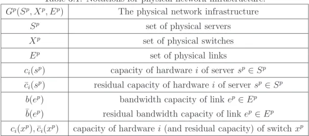
3.1 Notations for physical network infrastructure. . . 17
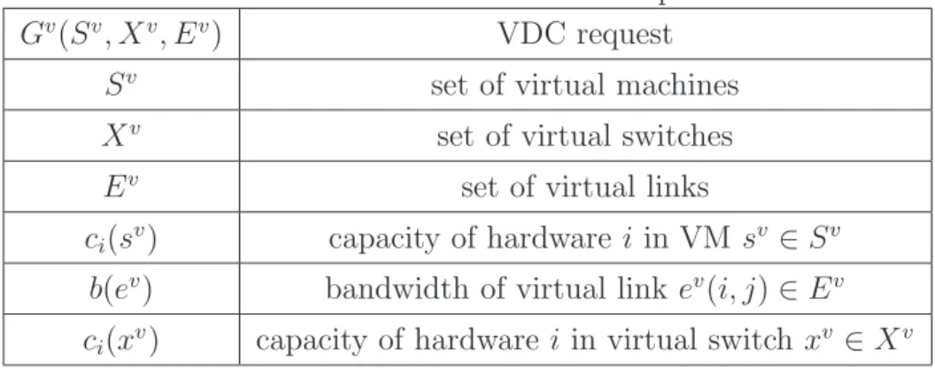
3.2 Notations for VDC request. . . 18
List of Figures
2.1 Conventional data center network topology. . . 7
2.2 Clos topology . . . 7
2.3 Fat-tree topology (k = 4). . . 8
2.4 Virtualization of a data center. . . 9
3.1 SecondNet architecture [29]. . . 13
3.2 VDC request abstractions in Oktopus [15]. . . 14
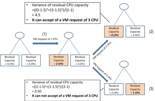
3.3 Using variance for resource defragmentation. . . 22
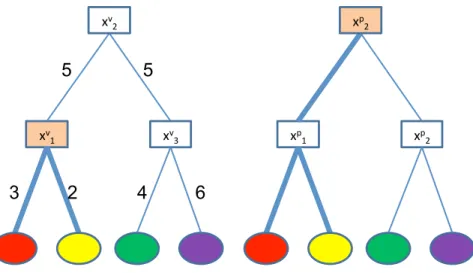
3.4 Minimizing communication cost . . . 23
3.5 Min-cost flow graph used for switch mapping. . . 26
3.6 Acceptance ratio and CPU utilization (VL2 topology). . . 30
3.7 Network utilization and revenue (VL2 topology).. . . 31
3.8 Acceptance ratio and CPU utilization (mix of VL2 and star topology). . . 32
3.9 Network utilization and revenue (mix of VL2 and star topology). . . 33
4.1 A sample VDC request and its embedding in physical data center. . . 40
4.2 Instantaneous Income . . . 49
4.3 Number of accepted VDCs. . . 50
4.4 Number of active physical machines over time . . . 50
4.5 Utilization of CPU, memory and bandwidth. . . 51
Publications
Journal Publications:• Md. Rabbani, M. F. Zhani, and R. Boutaba. On Achieving High Survivability in Virtualized Data Centers. IEICE Transactions on Communications. Vol. E97-B (1), January 2014.
• MF. Bari, R. Boutaba, R. Esteves, L. Granville, M. Podlesny, M. Rabbani, Q. Zhang and M. F. Zhani. Data Center Network Virtualization: A Survey. IEEE Communications Surveys and Tutorials. IEEE Press, Vol. 15(2), pp. 909-928, April 2013.
Conference Publications:
• Md. Rabbani, R. Esteves, M. Podlesny, G. Simon, L. Granville and R. Boutaba. On Tackling Virtual Data Center Embedding Problem. In Pro-ceedings of the IFIP/IEEE Integrated Network Management Symposium (IM). Ghent (Belgium), 27-31 May 2013.
Chapter 1
Introduction
With the increasing popularity of cloud computing, data centers have been widely deployed by companies such as Amazon, Google, Facebook, and Yahoo! to support large-scale applications and to store large volumes of data [1, 2, 20, 24]. Hence, hosting services in data centers has become a multi-billion dollar business that plays a crucial role in the future IT industry.
Traditionally, data centers use dedicated servers to run applications, resulting in poor server utilization and high operational cost. The situation improved with the emergence of server virtualization technologies (e.g., VMware [10], Xen [11]), which allow multiple Virtual Machines (VMs) to be collocated on a single physical server. These technologies are adopted by data center architectures proposed over the recent years [14,28,27]. These technologies can provide performance isolation between collocated VMs to improve ap-plication performance and security. However, server virtualization alone is insufficient to address all of the limitations of today’s data center architectures. In particular, data center networks still suffer from a number of limitations:
• No performance isolation: Many of today’s cloud applications, like search engines and web services have strict requirements on network performance in terms of latency and throughput. However, traditional networking technologies only provide best-effort delivery service with no performance isolation. Thus, it is difficult to provide predictable Quality of Service (QoS) for these applications. For example, MapReduce applications have strict constraints in terms of latency and throughput,that cannot be guaranteed through server virtualization alone [44].
• Increased security risks: Traditional data center networks do not restrict the commu-nication pattern and bandwidth usage of each application. As a result, the network is vulnerable to insider attacks such as Denial of Service (DoS) attacks [41].
• Poor application deployability: Many enterprise applications use application-specific protocols and address spaces [17]. Migrating these applications to data center envi-ronments is a major hurdle because it often requires cumbersome modifications to these protocols and eventually to the applications’ source codes.
• Limited management flexibility: In a data center environment where both servers and networks are shared among multiple applications, application owners often wish to control and manage the network fabric for a variety of purposes such as load balancing, fault diagnosis, and security protection. However, traditional data center network architectures do not provide the flexibility for different users to manage their communication fabric in a data center.
• No support for network innovation: Inflexibility of the traditional data center archi-tecture prohibits network innovation. As a result, it is difficult to introduce changes to traditional data center networks such as upgrading network protocols or intro-ducing new network services. In the long run, it will reduce the effectiveness of the initial capital investment in data center networks.
Motivated by these limitations, there is an emerging trend towards fully virtualized data center architectures [16]. As a result, recent research proposals have advocated offering both computing and networking resources in the form of Virtual Data Centers (VDCs). Basically, a VDC consists of virtual machines, routers and switches connected through virtual links with guaranteed bandwidth. This allows cloud providers to achieve better performance isolation between VDCs and to implement more fine-grained resource alloca-tion schemes. At the same time, VDCs allow service providers to guarantee predictable network performance for their applications.
In typical cloud environments, the Infrastructure Provider (InP) owns the physical infrastructure and leases resources to multiple Service Providers (SPs). Each SP then leverages its dedicated resources to deploy applications and services and offer them to end users over the Internet. So far, InPs mainly roll out computing resources (i.e., virtual machines) with no network performance guarantees [1, 7]. This results in a variable and unpredictable network performance in addition to potential security risks [15, 52, 36, 29]. Introducing VDCs will facilitate the possibility to implement customized network protocol and management policies, to minimize the impact of security threats, and to deploy new applications and services.
1.1
Motivation and Challenges
Allocating resources to VDCs is known as theVDC embedding or mapping problem. One of the main objectives of InPs is to accommodate as many VDC requests as possible and increase their revenue. Existing embedding solutions [29, 15] have proposed heuristics to cope with the NP-hardness of the problem. However, most of these proposals are heavily topology-dependent and hence cannot be generally applied to arbitrary data center topologies. More importantly, most of them usually focus on VM placement [29] and do not explicitly consider other types of resources (e.g., switches), which can limit their applicability in realistic scenarios. For example, researchers or some companies may want to test their own switching protocol that requires switches in VDC topology. Also, if InPs know in advance that their data centers are going to be affected by natural calamities, they can move their entire data center topology including servers and switches to other data centers. The requested VDC of the affected InP will include virtual switches in addition to VM. Hence, finding an efficient VDC embedding algorithm considering all of these aspects is a challenging task for InPs.
Another primary challenge that has not been adequately addressed so far is how to guarantee high VDC availability. On the one hand, for an SP, a service disruption, even for seconds, may incur high losses in revenue and also significantly impair the SP’s reputation. A recent study by an IT analyst firm estimated SP losses due to service downtime from US$25,000 up to US$150,000 per hour [3]. On the other hand, InPs could also incur significant penalties from not delivering the promised availability specified in the service level agreements. For instance, Amazon EC2 pledges to offer a service credit equal to 10% of the bill to any customer whose resources’ annual availability falls below 99.95% [1]. As a result, providing high resource availability has been pointed out as one of the primary challenges of InPs to exhort SPs to rely on the cloud.
Although, few proposals have addressed the issue of improving availability of VDCs, they assume physical components in data centers to be homogeneous in terms of failure rate and availability. However, in real environments, these characteristics are highly het-erogeneous and vary significantly depending on various parameters such as the types of the equipments and their age [25,47]. This observation suggests that, in order to achieve the desired VDC availability, the equipment heterogeneity must be considered to (1) determine the placement of VDC nodes and links and to (2) decide more accurately the number and the placement of the backup resources.
1.2
Contributions
The contributions of this thesis are threefold.
• We present a comprehensive background about data centers, the basic concepts of data center virtualization. We also discuss the business model associated in cloud environments. We also provide an extensive literature survey on VDC embedding and survivability schemes in virtualized data centers.
• We propose a new VDC embedding solution that, in addition to virtual machine placement, explicitly considers the embedding of virtual switches and links. Our proposed algorithm significantly increases the acceptance rate of VDCs and reduces the bandwidth usage in the data center network. In addition, unlike previous propos-als, our solution does not restrict the type of VDC topology that can be embedded. • Finally, we address the availability-aware resource allocation problem in virtualized data centers. Hence, we propose Hi-VI, a VDC management framework that allocates resources for VDCs while achieving the desired availability for each of them by pro-visioning backup resources and taking into account the availability of the underlying physical devices.
1.3
Thesis Organization
The remainder of the thesis is organized as follows.
Chapter 2 provides an overview of conventional data centers, the basic concepts of data center virtualization, and the business model commonly used in cloud environments. Chapter 3 surveys the existing proposals addressing VDC embedding, presents the for-mulation of the VDC embedding problem, and proposes a heuristic to solve this problem. Simulations are then conducted to evaluate the performance of the pro-posed heuristic compared to a baseline algorithm.
Chapter 4 presents previous works on failure characterization in data centers, summarizes the existing availability-aware VDC allocation schemes and their limitations, and proposes a resource allocation framework that takes into account the heterogeneity of data center computing and networking equipment to dynamically provision backup
resources and satisfy the desired availability for each VDC. Simulation results are then presented to show the effectiveness of our solution compared to a heterogeneity-oblivious solution.
Chapter 5 concludes the thesis with a summary of our contributions, and outlines po-tential directions for future research.
Chapter 2
Background
The aim of this chapter is to present the terminology relevant to data center virtualization. Table2.1provides a list of abbreviations used throughout the paper. We first provide some definitions related to data centers and we present an overview of conventional data centers in Section 2.1. Then we discuss data center virtualization technologies in Section 2.2. Finally, Section2.3 describes the main stakeholders in cloud environments.
2.1
Data Center
• A Data Center (DC) is a facility consisting of servers (physical machines), storage and network devices (e.g., switches, routers, and cables), power distribution systems, cooling systems. Table2.1provides a list of abbreviations used throughout the thesis. • A data center network is the communication infrastructure used in a data center, and is described by the network topology, routing/switching equipment, and the used protocols (e.g., Ethernet and IP). In the following, we present the main topologies used in data centers or recently proposed in the literature:
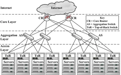
– Conventional data center network topology [12] (Figure 2.1): In this topology, each Top-of-Rack (ToR) switch in the access layer provides connectivity to the servers mounted in one rack. Each Aggregation Switch (AS) in the aggregation layer (sometimes referred to as distribution layer) forwards traffic from multiple ToR switches to the core layer. Every ToR switch is connected to multiple aggregation switches for redundancy. The core layer provides secure connectivity
Figure 2.1: Conventional data center network topology.
Figure 2.2: Clos topology
between aggregation switches and core routers (CR) connected to the Internet. A particular case of the conventional topology is theflat layer 2 topology, which uses only layer 2 switches.
– Clos topology is a topology built up from multiple stages of switches [23]. Each switch in a stage is connected to all switches in the next stage, which provides extensive path diversity. Figure 2.2 shows an example of a three-stage Clos topology.
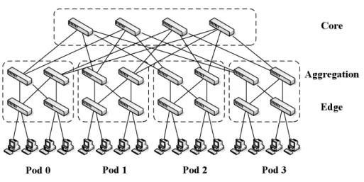
– Fat-tree topology[31] is a special type of Clos topology that is organized in a tree-like structure, as shown in Figure 2.3. The topology built of k-port switches contains k pods; each of them has two layers (aggregation and edge) of k/2
Figure 2.3: Fat-tree topology (k = 4)
switches. Each of (k/2)2 core switches has one port connected to each of k
pods. Thei-th port of any core switch is connected to podiso that consecutive ports in the aggregation layer of each pod switch are connected to core switches on k/2 strides. Each edge switch is directly connected to k/2 end-hosts; each of the remaining k/2 ports of an edge switch is connected to k/2 ports of an aggregation switch [14].
It is worth noting that data center network topologies are not limited to the topologies presented in this section. The interested reader can find a comparison of recently proposed data center network topologies in [34].
2.2
Data Center Virtualization
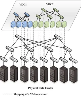
• A Virtualized Data Center is a data center where some or all of the hardware (e.g., servers, routers, switches, and links) are virtualized. Typically, physical hardware is virtualized using software or firmware called hypervisor that divides the equipment into multiple isolated and independent virtual instances. For example, a physical machine (server) is virtualized via a hypervisor that creates virtual machines (VMs) having different capacities (CPU, memory, disk space) and running different operat-ing systems and applications.
• A Virtual Data Center (VDC) is a collection of virtual resources (VMs, virtual switches, and virtual routers) connected via virtual links. While a Virtualized Data
Center is a physical data center with deployed resource virtualization techniques, a Virtual Data Center is an abstraction of resource allocation. A user can request resources in the form of VDC to the owner of virtualized data center. A Virtual Network (VN) is a set of virtual networking resources: virtual nodes (end-hosts, switches, routers) and virtual links; thus, a VN is a part of a VDC. A network vir-tualization level is one of the layers of the network stack (application to physical) in which the virtualization is introduced. In Figure2.4, we show how several VDCs can be deployed over a virtualized data center.
Figure 2.4: Virtualization of a data center.
Both network virtualization and data center virtualization rely on virtualization tech-niques to partition available resources and share them among different users, however they differ in various aspects. While virtualized ISP networks mostly consist of packet forwarding elements (e.g., routers), virtualized data center networks involve differ-ent types of nodes including servers, routers, switches, and storage nodes. Hence, unlike a VN, a VDC is composed of different types of virtual nodes (e.g., VMs, vir-tual switches and virvir-tual routers) with diverse resources (e.g., CPU, memory and disk). In addition, in the context of network virtualization, virtual links are charac-terized by their bandwidth. Propagation delay is an important metric when nodes are geographically distributed. However, since a data center network covers a small
geographic area, the propagation delay between nodes is negligible; hence, it is al-ways ignored when defining VDC virtual links [29, 15]. Low latency requirements are becoming increasingly important.
Another key difference between data center networks and ISP networks is the number of nodes. While the number of nodes in ISP backbones is in order of hundreds (e.g., 471, 487, and 862 nodes in Sprintlink, AT&T, and Verio ISPs, respectively [42]), it can go up to thousands in today’s data centers (e.g., around 12000 servers in one Google Compute cluster [51]). Hence, the solutions to embedding problem in the VN domain can potentially raise scalability issues, and increase management complexity. Furthermore, different from ISP networks, data center networks are built using topologies like the conventional tree, fat-tree, or Clos topologies with well defined properties, that allows to develop embedding algorithms optimized for such particu-lar topologies (e.g., Ballaniet al. [15] proposed an embedding scheme applicable only to tree topology).
In summary, data center network virtualization is different from ISP network vir-tualization, because one has to consider different constraints and resources, specific topologies, and degrees of scalability. [21] presents a survey of ISP network virtual-ization techniques.
Table 2.1: List of abbreviations Acronym Description
DC Data Center
V M Virtual Machine
V N Virtual Network
V DC Virtual Data Center
V LAN Virtual Local Area Network
T oR Top-of-Rack
AS Aggregation Switch
CR Core Router
InP Infrastructure Provider
SP Service Provider
2.3
Business Model
In this section, we describe main stakeholders in cloud environments. One of the differences between the traditional networking model and network virtualization model is participating players. In particular, whereas the former assumes that there are two players: ISPs and end-users, the latter proposes to separate the role of the traditional ISP into two: an Infrastructure Provider(InP) and aService Provider (SP). Decoupling SPs from InPs adds opportunities for network innovation since it separates the role of deploying networking mechanisms,i.e., protocols, services (i.e., SP) from the role of owning and maintaining the physical infrastructure (i.e., InP).
In the context of data center virtualization, an InP is a company that owns and manages the physical infrastructure of a data center. An InP leases virtualized resources to multiple service providers/tenants. Each tenant creates a VDC over the physical infrastructure owned by the InP for further deployment of services and applications offered to end-users. Thus, several SPs can deploy their coexisting heterogeneous network architectures required for delivering services and applications over the same physical data center infrastructure. The end-users use services and applications offered by SPs.
2.4
Summary
In this chapter, we provided the terminologies related to data center virtualization. We described the components of a data center, and different network topologies used in data centers. We also provided the definition of virtualized/virtual data centers, and the main stakeholders in a typical cloud environment. In the next chapter, we present a resource allocation scheme that allows InPs to efficiently allocate resources to VDCs with the goal of maximizing the revenue while minimizing bandwidth usage in the data center network.
Chapter 3
Virtual Data Center Embedding
3.1
Introduction
The mapping of virtual resources to physical ones is commonly known as the VDC em-bedding problem. Devising efficient VDC emem-bedding algorithms is crucial to accept a high number of VDC requests, which in turn impacts the revenue of the InP. In this section, we deal with the problem of VDC embedding. We define a VDC in a generic way, where we distinguish multiple resource types. We typically observe that the providers of inter-active multimedia applications require GPU in their VMs while other SPs are interested in very fast memory hardware (SRAM) [36]. An InP should be able to differentiate these different hardware in order to serve a vast range of SPs. We also go further by defining virtual switches and virtual links. We believe that an SP running applications with strict network requirements is interested in renting a very precise network infrastructure for the connection between its VMs. Protocols related to Software-Defined Networking (SDN) can provide some guarantees but a full isolation of applications can only be offered by the vir-tualization of switches. In addition, switch virvir-tualization provides SPs with the possibility of defining their own forwarding protocols.
As the VDC embedding problem is NP-hard, we design a heuristic solution based on three embedding phases: VM mapping, link mapping, and switch mapping. We explicitly include in our heuristic different data center resources such as switches and storage. More-over, we clearly distinguish physical servers and network nodes (i.e., switches). To increase the chances of successful VDC embedding, our solution includes two features. First, it allows multiple VMs of a single VDC request to be embedded in the same physical server,
which is not considered in some previous proposals. Second, we leverage the coordination between switch mapping and link mapping phases.
The rest of this chapter is organized as follows. Existing literature on VDC embedding is described in Section 3.2. Then, in Section3.3, we formalize the data center network model and the VDC embedding problem. In Section 3.4, we propose our algorithm for VDC embedding based on coordinated switch and link mapping. In Section3.5, we present the performance evaluation of the proposed algorithm. Finally, we conclude in Section3.6.
3.2
Literature Survey
The mapping of virtual resources to physical has been the subject of extensive research in the context of network virtualization [50, 22,38,19]. Several proposals have been made to cope with the NP-hardness of the embedding problem.
SecondNet [29] proposes Virtual Data Centers (VDCs) as the abstraction for resource allocation in multi-tenant cloud environments. The goal of SecondNet is to provide band-width guarantees by designing a scalable and deployable VDC embedding algorithm. Sec-ondNet aims at increasing the utilization of the network.
Figure 3.1: SecondNet architecture [29].
The main component of the SecondNet architecture (Figure 3.1) is the VDC manager that creates VDCs based on a requirement matrix that defines the requested bandwidth
between VM pairs. SecondNet defines three basic service types: a high priority end-to-end guaranteed service (type 0), a better than best-effort service (type 1) that offers bandwidth guarantees for the first/last hops of a path, and a best-effort service (type 2).
Performance of the proposed allocation algorithm in SecondNet depends on the physical network topology. For instance, the data center network utilization is reported to be high for a BCube topology but low for fat-tree and VL2 topologies. SecondNet does not consider different types of resources (e.g., storage servers, switches, routers, links) found in real data centers. We explained in Section 1.1 about the importance of considering virtual switches in addition to VMs.
Oktopus [15] is a data center network architecture that implements two virtual data center abstractions (i.e., virtual cluster and virtual oversubscribed cluster).
(a) Virtual cluster (b) Virtual oversubscribed cluster
Figure 3.2: VDC request abstractions in Oktopus [15].
A virtual cluster (Figure 3.2(a)) provides the illusion of having all VMs connected to a single non-oversubscribed virtual switch. However, a virtual oversubscribed cluster (Figure 3.2(b)) emulates an oversubscribed two-tier cluster consisting of a virtual root switch that interconnects a set of virtual clusters. A tenant can choose the abstraction and the degree of the oversubscription of the virtual network based on the communication pattern of the applications to be deployed in the VDC (e.g., user-facing web-applications, data intensive applications). Oktopus uses a greedy algorithm for the resource allocation to the VDCs that aims at finding the best trade-off between the performance guarantees offered to tenants, their costs, and the provider revenue. They try to map the VDC requests to the smallest sub-tree of the data center topology with the least amount of residual bandwidth on the links connecting the sub-tree to the rest of the topology.
Oktopus has some limitations. It supports only two types of VDC requests. Besides, it can be applied only in tree-like physical topologies.
The Traffic-Aware Virtual Machine Placement Problem (TVMPP) [32] focuses on im-proving the scalability of data center networks by optimizing the VM placement. The main idea is to minimize the overall communication cost of the data center by placing VMs that have heavy traffic among them close to each other, thus avoiding network bottlenecks in the data center. A two-tier algorithm , called Cluster and Cut, is proposed to solve the problem.
One limitation of this proposal consists in the fact that traffic and cost matrices must be known in advance. In a realistic scenario, VMs can belong to different tenants, which in turn run applications with different traffic patterns that may not be known prior to the application deployment. Besides, other types of virtual resources (networking, storage) that exist in a data center are not considered in this work.
NetShare [30] tackles the problem of bandwidth allocation in virtualized data center networks proposing a statistical multiplexing mechanism that does not require any changes in switches or routers. NetShare allocates bandwidth for tenants in a proportional way and achieves high link utilization for infrastructure providers. In NetShare, data center network links are shared among services, applications, or corporate groups, rather than among individual connections. In this way, one service/application/group cannot hog the available bandwidth by opening more connections.
Scalability of NetShare can be an issue because queues have to be configured at each switch port for each service/application. In addition, NetShare aims to achieve fairness in bandwidth allocation, and, thus, does not provide any absolute bandwidth guarantees to services.
Seawall [41] is a bandwidth allocation scheme that allows InPs to define how the band-width will be shared in a data center network with multiple tenants. The idea of Seawall is to assign weights to network entities generating traffic (e.g., VMs, process), and to allo-cate bandwidth according to these weights in a proportional way. Seawall overcomes the scalability problem associated with NetShare, by mapping many VMs onto a small, fixed number of queues.
Both NetShare and Seawall aim to achieve fairness in bandwidth allocation, and, thus, does not provide any absolute bandwidth guarantees to services.
Gatekeeper [39] focuses on providing guaranteed bandwidth among VMs in a multi-tenant data center, and achieving a high bandwidth utilization. Bandwidth allocation is done by defining both the minimum guaranteed rate and maximum allowed rate for each
VM pair. These parameters can be configured to achieve minimum bandwidth guarantee, while ensuring that link capacities are effectively utilized by tenants.
Gatekeeper only works for full bisection-bandwidth networks and focuses on preventing congestion on access links. However, it assumes no congestion at the core links which might be optimistic.
FairCloud [33] tackles the tradeoffs among minimum bandwidth guarantees, network utilization and fairness for sharing networks in multitenant data centers. To address this issue, it proposes three bandwidth allocation policies. However, these weight-based com-peting mechanisms can not provide bandwidth guarantees for VMs.
VINEYard [22] is a set of online embedding algorithms for virtual networks that coordi-nates the node and link mapping phases. The motivation behind this coordinated mapping relies on the fact that ignoring the relation between node and link mapping can lead to poor performance. In VINEYard, the virtual network embedding problem is formulated as a mixed integer program that includes both node and link-related constraints. In order to be solved in polynomial time, the MIP formulation is transformed into a linear program through constraint relaxation. The main objective of VINEYard is to minimize the cost of embedding a VN request to a physical substrate and, consequently, increase the InP revenue.
The limitation of VINEYard in the context of data center is that is does not consider explicitly other types of virtual resources that can exist in a data center and that have specific requirements, like ingress and egress bandwidth and storage capacity. Besides, it assumes that the substrate supports path splitting, which is not true for all data center environments.
These are the most prominent proposals of VDC embedding problem and bandwidth sharing mechanism in multitenant data centers. We find that most of these proposals are only applicable to tree-like proposals. Most of them also do not explicitly consider other types of resources (e.g., storage servers, switches, routers, links) and their associated constraints, which can limit their applicability in real environments. Other bandwidth sharing proposals cannot provide guaranteed bandwidth for VDCs. In the following, we propose our VDC embedding algorithm that overcomes the aforementioned limitations.
3.3
Problem Formulation
We provide now our network model and we mathematically formulate the VDC embedding problem. Used notations are provided in Table 3.1 and Table 3.2.
Table 3.1: Notations for physical network infrastructure.
Gp(Sp, Xp, Ep) The physical network infrastructure
Sp set of physical servers
Xp set of physical switches
Ep set of physical links
ci(sp) capacity of hardware i of server sp ∈Sp ¯
ci(sp) residual capacity of hardware i of server sp ∈Sp
b(ep) bandwidth capacity of link ep ∈Ep ¯b(ep) residual bandwidth capacity of link ep ∈Ep
ci(xp),¯ci(xp) capacity of hardware i (and residual capacity) of switch xp
3.3.1
Physical Data Center
The InP owns a physical data center network, which is modeled as a weighted undirected graph, Gp(Sp, Xp, Ep), where Sp is the set of physical servers, Xp is the set of physical switches and Ep is the set of physical links.
We associate with each physical server inSp a set of featured hardware, which typically includes CPU, data storage memory, Graphical Processing Unit (GPU), and fast SRAM memory. A part of each of these hardware can be reserved by a tenant. To preserve the generality of our model, we associate with each physical server sp ∈ Sp a set of featured capacities ci(sp), i∈ {1, . . . , k}where k is the number of different reservable specific hard-ware capacities. For example, c1(sp) and c2(sp) can refer to CPU and memory capacities
respectively. We also keep track of the residual capacity for each hardware after some parts of these hardware have been rented by a tenant. We note ¯ci(sp) the residual capacity for hardwarei∈ {1, . . . , k}.
We also associate with each physical link ep in Ep a bandwidth capacity, noted b(ep), and the residual bandwidth capacity, noted ¯b(ep). Please note that this capacity can be extended with a subscript in the same manner as for the capacity of physical servers.
One of the novelties of our model is that we also introduce resources for switches. We consider each buffer of each switch port and we allow a SP to partially rent each of these buffers. Thus, a SP is able to very precisely adjust packet losses and processing in every port. To simplify, we use the same notations as for the virtual servers, so ci(xp) is the capacity of the hardware iin the virtual switch xp.
3.3.2
VDC Request
The clients of the InP are entities that would like to reserve a subset of InP’s physical infrastructure. We call a VDC request what a tenant wants to reserve. The VDC request is also modelled as a weighted undirected graph, which we note Gv(Sv, Xv, Ev), where Sv is the set of VMs, Xv is the set of virtual switches andEv is the set of virtual links.
Table 3.2: Notations for VDC request.
Gv(Sv, Xv, Ev) VDC request
Sv set of virtual machines
Xv set of virtual switches
Ev set of virtual links
ci(sv) capacity of hardware i in VM sv ∈Sv
b(ev) bandwidth of virtual link ev(i, j)∈Ev
ci(xv) capacity of hardware i in virtual switch xv ∈Xv
We keep the same notations as for the physical infrastructure for the specific required capacities of VMs and virtual links. Thus, ci(ep) and b(ep) refer respectively to the re-quested capacity of hardware ion VM sv and the requested bandwidth capacity of virtual link ev respectively.
3.3.3
Objective
The goal of an InP is to maximize its profits through an optimal exploitation of its infras-tructure. This objective is related to maximizing the number of VDC requests that are successfully embedded in the physical infrastructure subject to embedding constraints.
Another challenge for InP is that tenants do not coordinate to request VDC. Thus, VDC requests do not arrive at the same time. Hence the problem faced by InPs is an online problem where the inputs (here the VDC requests) have to be processed iteratively, without knowledge of the future VDCs. Let consider a VDC request Gv, which is received by the InP while a part of its infrastructure has already been reserved. We express in the following the constraints for the embedding of Gv. We first have to define the output variables.
Letxuv be a set of binary variables for the mapping of equipmentu ∈Sv (respectively
u∈Xv) into a physical server v ∈Sp (respectively v ∈Xp).
xuv =
1 if u is embedded into v
0 otherwise
Lety(uu′)(vv′) be a set of binary variables for the mapping of virtual link (uu′)∈Ev into
physical link (vv′)∈Ep.
y(uu′)(vv′)=
1 if (uu′) is embedded into (vv′) 0 otherwise
An embedding can be done if the following constraints are fulfilled for the mapping of equipments. X v∈Sp∪Xp xuv = 1, ∀u∈Sv∪Xv (3.1) X u∈Sv∪Xv xuv×ci(u)≤¯ci(v), ∀v ∈Sp∪Xp,∀i (3.2)
Constraint (3.1) ensures that a VM is embedded into one and only one physical server. It also makes sure that all VMs are embedded. Constraint (3.2) guarantees that the capacities of physical servers are not overused by the embedded VMs.
For the link mapping, here are the constraints:
X (vv′)∈Ep y(uu′)(vv′)≥1, ∀(uu′)∈Ev (3.3) X (uu′)∈Ev y(uu′)(vv′)×b((uu′))≤¯b((vv′)), ∀(vv′)∈Ep (3.4) xuv = 1, xu′v′ = 1,∀u, u′ ∈Sv∪Xv (3.5)
Constraint (3.3) ensures that a virtual link can be mapped to several physical links or a physical path. All the links vv′ ∈ Ep, that any uu′ ∈ Ev is mapped to, form a path between physical servers where u and u′ are mapped. Constraint (3.4) guarantees that physical links have enough bandwidth to host embedded virtual links. Constraint (3.5)
indicates that selected links belong to the physical devices xv and xv′ hosting the virtual
devices xu and xu′, respectively.
For one given VDC and one infrastructure configuration, several embeddings can fulfill all above constraints. But some of them succeed in preserving “nearby” resources for future VDCs although others barely allow the next VDCs to be embedded. The quality of the online embedding algorithm for VDCs directly relates to the capacity of the embedding algorithm to be friendly for the next VDCs.
3.4
Proposed Solution
Optimization problems for embeddings that include both nodes and links are known to be NP-hard. For practical implementations, heuristics are needed. We discuss in the next sub-section the main principles of an iterative three-steps algorithm for the embedding. We go into the details of our main proposal in sub-section 3.4.3.
3.4.1
Description of the three phase embedding
For the processing of a new VDCGv, an iterative heuristic consists of the three following rounds.
Phase I: VMs mapping – in this first step, the objective is to map each VM inSv into one physical server. The mapping should respect the constraints in Equation (3.2), that is, the physical server that host a VM should have enough capacity. Various strategies can be implemented. With regard to the following steps, the proximity of the selected physical servers is critical.
Phase II: Virtual switches mapping – the second step is about mapping each virtual switch in Xv to a physical switch. Besides constraints (3.2), the main idea here is to associate virtual switches to physical ones while taking into account the previous VM mapping. It makes more sense to map a virtual switch between two already embedded VM so that the distance between the chosen physical switch and the physical servers that host the VM is small.
Phase III: Virtual links mapping – the final step is to map the virtual links into physi-cal links, with respect to constraints (3.4). Many paths can exist between two physical servers in the real topology. The goal here is to find the paths between the physical
servers that host the virtual equipments that are given in Ev so that all virtual links can be embedded.
In this heuristic, each step critically impacts the following steps because the input of each phase depends on the output of the previous phase. Therefore, we have to implement a mechanism that allows to get back to a previous phase if ever one phase cannot be fulfilled. For example, the impossibility to find a mapping for virtual switches does not mean that the whole VDC cannot be embedded. Another VM mapping may enable a successful switch mapping. On the other hands, a heuristic does not explore all possible solutions. A trade-off should be found between the number of tested solutions allowed by such a retro-mechanism and the efficiency of the whole algorithm, which should be fast.
We present now our heuristic. First, we present the rationale of our solutions. Then, we describe our implementations of the three steps.
3.4.2
Rationale for the Objectives
The main idea of our heuristic is to reduce server fragmentation, minimize communication costs between VMs and virtual switches, increase the residual bandwidth of the network, and offer load balancing capabilities to the network. For the sake of simplicity, we consider only one resource for the server (e.g., CPU).
Reduce server fragmentation. We use the variance of the residual CPU capacity of the physical servers. The rationale behind using variance in server defragmentation is explained in Figure 3.3 with basic physical topology. Initially, two physical servers have residual capacity of 3 CPU units each. After receiving a VM request (1) of 1 CPU unit, the residual CPU of the servers become 2 CPU units and 3 CPU units. A future VM request of 2 CPU units has two possible mappings. In the first one (2), the residual CPU of one server is 3 CPU units, which allows a future VM request requiring 3 CPU units. In the second mapping (3), the residual CPU of the servers are 2 CPU units and 1 CPU unit. In this latter case, a future VM request with 3 CPU cannot be accepted. The variance of the residual CPU capacity in the first allocation is 4.5 and 0.5 in the second allocation. We observe that the higher the variance is, the higher the resource defragmentation is and higher the possibility of accepting higher number of VDC requests.
Let (¯ci) be the average residual capacity of hardware i (here we have only CPU, rep-resented by c1) over all nodes sp. Formally, the solution that we select among all possible
! • !"#$"%&'!()!#'*$+,"-!./0!&"1"&$23! 445 6 789:4; 6 7898<49 68 =445"6>789:4;"6>7898<49"68 =!?>7 • !"!#$%!$##&'"!()!$!*+!,&-.&/"!()!0!123 @'*$+,"-! ."1"&$23! =!4!123 @'*$+,"-! ."1"&$23! =!;!./0 !A!#'B,'*2!()!6 ./0 @'*$+,"-! ."1"&$23! =!;!./0 @'*$+,"-! ."1"&$23! =!;!./0 @'*$+,"-! ."1"&$23! =!5 123 @'*$+,"-! ."1"&$23! =!;!./0 @'*$+,"-! ."1"&$23! =!9!./0 @'*$+,"-! ."1"&$23! =!6!123 • !"#$"%&'!()!#'*$+,"-!./0!&"1"&$23! =449"6>789:46 "6>7898<49 "68 =!5>75 ? • !"!#$%!%("!$##&'"!()!$!*+!,&-.&/"!()!0!123 (1) (2) (3)
Figure 3.3: Using variance for resource defragmentation. is defined as: Vcpu = |Sp| P u∈Sp ¯ c1(u)−¯c1 2 (3.6)
Minimize communication cost and increase residual bandwidth. We consider the hop-count between the virtual nodes (i.e., VM or virtual switch) multiplied by the corresponding requested bandwidth of the virtual link connecting the two virtual nodes. For example, in Figure 3.4 the cost of mapping virtual switch xv
1 (Fig. 3.4(a)) to physical
switch xp2 (Fig. 3.4(b)) is 2 (hop count from physical switch xp2 to the red physical server) ×3 (bandwidth required between the virtual switch xv
1 and the red virtual server) +2
(hop count from physical switch xp2 to the yellow physical server) ×2 (bandwidth required
between the virtual switch xv
1 and theyellow virtual server) = 10, if we consider only the
red and yellow virtual machines, which are the closest ones to the virtual switch xv
1.
A solution that matches our needs takes into account Vsw, which is defined as: Vsw = X (vv′)∈Ep X (uu′)∈Ev y(uu′)(vv′)×b((uu′))×hop count(vv′) (3.7)
!" #$ ! " %$ !" &$ 3 5 2 4 6 5
(a) Virtual request
!"
#$ !"%$
!" %$
(b) Physical network
Figure 3.4: Minimizing communication cost
Load balancing link. Mapping virtual switches to some location can possibly require a high number of virtual links than mapping them to other locations, and result in network bottlenecks. In order to avoid bottleneck of physical links, we also use load balancing for virtual links having the same communication cost by minimizing the variance of the residual network bandwidth.
In the same manner as for Vcpu, we define Vlink as:
Vlink= P (vv′)∈Ep ¯ b(vv′)−(¯b)2 |Ep| (3.8)
Overall Optimization. In order to consider all aforementioned objectives, we define one unique objective, which is to minimize:
α× Vsw+β× Vcpu+γ× Vlink (3.9)
Since such optimization problem of VDC embedding is NP hard [29], we present a heuristic (shown in Algorithm1) to solve the problem that has three phases: VM mapping, virtual switch mapping, and virtual link mapping. In order to achieve locality of the VMs, we try to start the mapping process from one physical server. If any of the three phases fails, we increase the number of physical servers adding one adjacent server and try the mapping process again, until we consider all the physical servers in the data center.
Algorithm 1 VDC Embedding Algorithm
1: for (|Sp|= 1;|Sp| ≤T otalNumberof Servers;Sp =Sp∪ {AdjacentServer}) do 2: VM Mapping:
3: Sort the VMs, sv ∈Sv according the requested 4: resource capacity
5: for each sv ∈Sv do 6: for each sp ∈Sp do
7: Add an edge fromsv tosp if sp satisfies the 8: capacities of sv
9: end for
10: Add a source node and add an edge from source 11: node to sv.
12: Add a destination node and add an edge from 13: each of sp to destination node.
14: Solve min-cost flow problem and goto line 1 if fails 15: update residual capacities of sp.
16: end for
17: Switch Mapping: 18: for each xv ∈Xv do 19: for each xp ∈Xp do
20: Add an edge fromxv toxp if xp satisfies the 21: capacities of xv
22: end for 23: end for
24: Add a source node and add an edge from source 25: node to each ofsv.
26: Add a destination node and add an edge from each 27: of sp to destination node.
28: Solve min-cost flow problem and go to line 1 if fails 29: update residual capacities ofxp.
30: Link Mapping: 31: for each ev ∈Ev do
32: Remove each ep ∈Ep where b(ep)< b(ev) 33: Run BFS to compute the shortest path and go 34: to line 1, if no path found
35: Update capacity of each linkep in that path 36: end for
3.4.3
VDC Mapping
In the following, we describe the three phases of the embedding involved in our proposed solution.
VM Mapping In the VM mapping, we map VMs to the physical servers; we do it se-quentially so that more than one VM can be mapped to one physical server. In the beginning, requested VMs are sorted according to a requested resource capacity in a descending order. Thus, we can reject a request quickly if there is not enough capacity to satisfy the request. Then we map VMs sequentially so that more than one VM can be mapped to a physical server. First, we take the first VM in the sorted list and find all the physical servers that can satisfy the resource requirements of the VM. Then, we map the VM to the physical server that minimizes the fragmentation cost. The cost function a(sp) for each server sp is defined by,
a(sp) = b(sp)× 1 |¯c1(sp)−c¯1|
(3.10) whereb(sp) is the used bandwidth of the serversp and (¯c
1) is the mean of the residual
CPU of the physical servers. We rely on the used bandwidth of physical servers for load balancing, and on the difference between the residual resource capacity and the average resource capacity of physical servers for server defragmentation, that will satisfy our objectives mentioned in Section 3.4.2.
Switch Mapping After mapping VMs, we proceed to switch mapping. Similar to VM mapping, we build a bipartite graph keeping virtual switches in the left and the physical switches in the right. Then, we add an edge from a virtual switch i to a physical switch j if the residual capacity of the physical switch j can satisfy the requested capacity of the virtual switch i. We add a source node s at the left of the virtual switches and a destination node d at the right of the physical switches. Following that, we add an edge from the source nodes to each of the virtual switches and an edge from each of the physical switches to the destination node d, as shown in Figure 3.5. This reduced the switch mapping problem to finding min-cost flow from source s to destination d.
Minimize X
(i,j)∈E
Figure 3.5: Min-cost flow graph used for switch mapping. where, x(i, j) ∈ {0,1} X j∈V x(i, j) = 0,for all i6=s, t X j∈V
x(s, j) = number of virtual switches
X
i∈P
x(i, t) = number of physical switches
E = Set of edges in the graph
V = Set of virtual switches in the graph
P = Set of physical switches in the graph
s = source node of the graph
t = destination node of the graph
(3.12) The cost function a(i, j) for each edge between a virtual switch i and a physical switchj is defined bya(i, j) =P
[hop count(j, m)×bandwidth(i, n)], wherem∈Sp,
n ∈Sv, and n is mapped into m. The intuition behind the cost function is to map the virtual switch to the physical switch that offers the lowest communication cost (hop count×bandwidth) for VMs of the same VDC connecting to the virtual switch
i. The cost function described above is used as the weight for each edge in the graph of min-cost flow problem. The variable x(i, j) gives the mapping of virtual switches
to physical switches. If the value of x(i, j) is 1, it indicates that the virtual switch i
is mapped to the physical switch j. By considering the bandwidth of the links when mapping switches, the algorithm increases the residual bandwidth of the network, which ultimately results in higher acceptance ratio of VDC requests.
Link Mapping Finally, we start link mapping after finishing the node mapping and switch mapping. We map each of the virtual links to physical links one by one. Before allocating any link, we first remove all the physical links having residual bandwidth capacity less than the requested bandwidth capacity of the virtual link. Then, we calculate the shortest path between the physical nodes, where the source and destination nodes of the virtual link are mapped, to reduce the communication cost. We use Breadth First Search (BFS) algorithm to find the unweighted shortest path.
3.5
Performance Evaluation
We studied the performance of our VDC allocation algorithm through simulation. In this section, we describe the simulation environments followed by performance metrics and result analysis. We have shown that our VDC algorithm can embed VDC requests that include virtual switches.
As no other existing work consider switch mapping in VDC embedding algorithm, we have shown the advantages of our algorithm for VDC allocation by comparing acceptance ratio, network and CPU utilization with a baseline algorithm of randomized heuristic. We illustrate the presentation of the iterative heuristic by an example: a simple algorithm based on randomized processes. For each VM, a physical server is randomly picked and if it has the capacity to host the VM, the algorithm processes the next VM, otherwise another physical server is picked. This algorithm iterates on the whole set of VMs until all VMs are successfully mapped. The switch mapping is done in the same manner. Finally, the link mapping is done by computing the shortest path for every virtual links.
3.5.1
Simulation Environment
We implemented a discrete event simulator for the evaluation of our proposed algorithm using C++ and used the open source C++ template library LEMON (Library for Efficient Modelling and Optimization in Networks) [8] to solve minimum-cost flow problem.
We used VL2 [27] topology for our physical data center network topology. Our physical data center has 24 servers, 22 switches and 144 links. The links between servers and ToR (top-of-rack) switches have bandwidth 1000 unit whereas the links between ToR switches and aggregate switches have 10 000 units and the links between aggregate switches and intermediate switches have the capacities of 10 000 units. The normalized values of CPU and storage were real numbers, uniformly distributed between 0.5 and 1.
For the VDC requests, we used the VL2 topology, star topology and mixed of them. For all the topologies, the CPU and storage of the VMs were real numbers uniformly distributed between 0 and 0.08. For the VL2 topology, the bandwidth of the links between servers and ToR switches, ToR switches and aggregate switches, and aggregate switches and intermediate switches, were uniformly distributed from 1 to 100, 1 to 1000, and 1 to 1000 respectively. For the start topology, the number of VMs are uniformly distributed from 3 to 10 and the links between the switch and the servers have bandwidth, uniformly distributed from 1 to 100. The VDC requests arrived in a Poisson process. The durations of the VDC requests were following a Poisson distribution having average of 500 time units. Our embedding algorithm serves the VDC requests online and with the passage of time, VDC requests, whose duration have passed, leave the physical data center and new VDC requests arrive. We also consider the case where only switches are mapped randomly while VMs are mapped according to our heuristic.
3.5.2
Performance Metrics
Acceptance Ratio
The acceptance ratio of a certain point of time is the ratio of the number of accepted VDC requests and the total number of VDC requests until that time. This gives a sense of how well an algorithm is performing, but can not completely capture the whole picture of the performance. An algorithm may accept more number of smaller VDC requests which can end up less revenue.
CPU Utilization
The CPU utilization is the total CPU used for embedding VDC requests divided by the total CPU capacity of the physical data center at a certain point of time, which is expressed as percentage.
Network Utilization
The network utilization is the total bandwidth of the links used for embedding VDC request divided by the total bandwidth capacity of the physical data center at a certain point of time, which is also expressed as percentage.
Revenue
We also computed the revenue generated for an embedding algorithm over time. Revenues are expressed in terms of allocated resources. We have used a revenue model [50] where revenue is considered as sum of bandwidth and CPU.α is used to strike a balance between the two resources.
Revenue(Gv) = X ev∈Ep b(ev) +α X sp∈Sp c1(sp)
3.5.3
Simulation Results
After running the simulation, we observed that our algorithm was able to embed the VMs as well as the virtual switches to the physical resources. It also embeds both types of topologies which shows the ability of our algorithm to embed VDC of any topology. To show the effectiveness of our algorithm, we compared our algorithm with random switch mapping and random VM mapping. Figure3.6and3.7 show the comparison of performance metrics of our algorithm with random switch mapping and random VM and switch mapping when VL2 topologies were used for input VDC requests. Our algorithm outperforms the random algorithms in terms of each of the metrics. For example, at 20 000 time unit, our algorithm has 0.83 acceptance ratio whereas the random switch mapping and random VM and switch mapping algorithms have acceptance ratio of 0.68 and 0.66 respectively. Our algorithm also has higher CPU and network utilization and revenue. As our algorithm considers the used CPU and bandwidth of the servers while doing VM mapping and bandwidth of the links while doing switch mapping, it can accept higher number of VDC requests as well as higher revenue.
Figure3.8and3.9 show the comparison of performance metrics of the algorithms when both VL2 topologies and star topologies were used for input VDC requests. Here, again we see that our algorithm outperforms the random algorithms in terms of each of the metrics. But here the random algorithms comparatively perform better than for the VL2 only topologies. Because, VDC requests of star topology were added to the input. Star topology has only one virtual switch and all the VMs are connected to the switch. So,
0.6 0.65 0.7 0.75 0.8 0.85 0.9 0.95 1 0 5000 10000 15000 20000 25000 Acceptance Ratio Time Our algorithm Random switch mapping Random VM and switch mapping
(a) Comparison of acceptance ratio over time.
0 10 20 30 40 50 60 70 0 5000 10000 15000 20000 25000 CPU Utilization (%) Time Our algorithm Random switch mapping Random VM and switch mapping
(b) Comparison of CPU Utilization over time.
Figure 3.6: Acceptance ratio and CPU utilization (VL2 topology).
there is less diversity for the embedding algorithm, specially for the switch mapping. Our algorithm has higher acceptance ratio, CPU and network utilization and revenue than the other two algorithms. We also observe that random switch mapping performs better than random VM and switch mapping because random switch mapping utilizes our VM mapping phase for its VM mapping. In both of the above cases, our algorithm has higher acceptance ratio, as well as, higher revenue, which demonstrates the advantages of our VDC embedding algorithm.
0 5 10 15 20 25 30 35 40 45 50 0 5000 10000 15000 20000 25000 Network Utilization (%) Time Our algorithm Random switch mapping Random VM and switch mapping
(a) Comparison of network utilization over time.
0 2000 4000 6000 8000 10000 12000 14000 16000 0 5000 10000 15000 20000 25000 Revenue (K) Time Our algorithm Random switch mapping Random VM and switch mapping
(b) Comparison of revenue over time.
Figure 3.7: Network utilization and revenue (VL2 topology).
3.6
Summary
In this chapter, we first described the existing literature on the VDC embedding problem. Then we provided a new formulation of VDC embedding problem where virtual switches are considered in addition to VMs and virtual links in the VDC requests. After that we discussed a general approach to tackle the embedding problem and then we proposed a three-phase minimum-cost based heuristic to solve the embedding problem. We evaluated
0.7 0.75 0.8 0.85 0.9 0.95 1 0 2000 4000 6000 8000 10000 12000 14000 Acceptance Ratio Time Our algorithm Random switch mapping Random VM and switch mapping
(a) Comparison of acceptance ratio over time.
0 10 20 30 40 50 60 70 80 90 100 0 2000 4000 6000 8000 10000 12000 14000 CPU Utilization (%) Time Our algorithm Random switch mapping Random VM and switch mapping
(b) Comparison of CPU utilization over time.
Figure 3.8: Acceptance ratio and CPU utilization (mix of VL2 and star topology). the performance of our embedding algorithm using a discrete event simulator. We showed that our algorithm has higher acceptance ratio, CPU and network utilization, as well as higher revenue. We did not consider the availability of the VDC in this chapter. However, as service providers are increasingly hosting different business services, providing guaran-teed availability of VDCs becomes extremely important. In the next chapter, we propose an allocation scheme devised for providing guaranteed VDC availability.
0 5 10 15 20 25 30 35 40 45 0 2000 4000 6000 8000 10000 12000 14000 Network Utilization (%) Time Our algorithm Random switch mapping Random VM and switch mapping
(a) Comparison of network utilization over time.
0 1000 2000 3000 4000 5000 6000 7000 8000 9000 0 2000 4000 6000 8000 10000 12000 14000 Revenue (K) Time Our algorithm Random switch mapping Random VM and switch mapping
(b) Comparison of revenue over time.
Chapter 4
Survivable Virtual Data Center
Embedding
4.1
Introduction
In the previous chapter, we have proposed a resource allocation scheme for VDCs aiming to achieve maximizing revenue. However, we did not consider the availability of VDC in our embedding algorithm. Service disruption even for seconds, may cause high losses in revenue and reputation for an SP. On the other hand, InP may end up paying huge penalties for the violation of service level agreement. Hence, providing guaranteed availability of VDCs is of great importance both to SP and InP.
Recently, few proposals have been made to improve the availability of VDCs either through availability-aware resource allocation schemes or redundancy provisioning tech-niques [45, 25, 46, 18, 47]. However, these works did not consider the heterogeneity of the underlying physical components. In this chapter, we address this compelling challenge and proposeHigh-availabilityVirtualInfrastructure Management (Hi-VI) framework [35] that takes into account the heterogeneity of data center computing and networking equipments to dynamically provision backup resources in order to ensure the required VDC availability. The remainder of the chapter is organized as follows: Section 4.2 surveys previous work on failure characterization in data centers highlighting the heterogeneity in terms of failure rate and availability. We also summarize representative work on availability-aware VDC allocation schemes and discuss their limitations. We present in Section 4.3 and 4.4
formulation of the availability-aware VDC allocation problem. The proposed solution is then described in Section 4.4.2. Simulation results are discussed in Section 4.5. Finally, we draw our conclusions in Section 4.6.
4.2
Literature Survey
In this section, we present related work on data center failure characterization and repre-sentative proposals addressing survivable resource allocation in virtualized data centers.
4.2.1
Failure Characterization in Data Centers
Gillet al. [25] presented a large-scale study of failures in several Microsoft data centers over one year. The authors characterized failures of networking devices and assessed the impact of their failures and the effectiveness of network redundancy in data centers. Furthermore, they observed that the failure rates of different equipments can vary significantly depending on their type (servers, top-of-rack switches, aggregation switches, routers, load balancers) and model. For instance, Load Balancers (LBs) exhibit high probability of failure during one-year period (over 20%), whereas switches have lower failure probability (less than 5%). Furthermore, failure rates of different devices are unevenly distributed. For example, the number of failures across load balancers are highly variable with a few outlier LB devices experiencing more than 400 failures over the one year period. Finally, the analysis of failure traces revealed that correlated device and link failures are extremely rare.
Wuet al. [45] presented an automated failure mitigation system called NetPilot, which alleviates failures in large scale data center network before operators diagnose and repair the root cause. The authors built their system based on an analysis of failures in several production data center networks over a six-month period. They identified three main causes of failures: software failures which constitute 21% of the total number of failures, hardware failures accounting for 18% and finally misconfigurations, the most dominant source of the failures (38%). The authors found that usually simple steps of mitigation are very effective in reducing repair times. However, certain failures incur much more repair time and hence cause significant network downtime. This concurs with the finding of [27] that reported that more than 95% of network failures can be fixed within 10 minutes whereas at least 0.09% of them can take more than 10 days to resolve. This again shows the heterogeneity of the failures in terms of repair times and potential impact.

![Figure 3.1: SecondNet architecture [29].](https://thumb-us.123doks.com/thumbv2/123dok_us/10183513.2920833/24.918.273.656.616.905/figure-secondnet-architecture.webp)
![Figure 3.2: VDC request abstractions in Oktopus [15].](https://thumb-us.123doks.com/thumbv2/123dok_us/10183513.2920833/25.918.128.802.465.703/figure-vdc-request-abstractions-in-oktopus.webp)