Robot–Robot Gesturing for
Anchoring Representations
Polychronis Kondaxakis
, Member, IEEE, Khurram Gulzar
, Stefan Kinauer, Student Member, IEEE,
Iasonas Kokkinos, Member, IEEE, and Ville Kyrki
, Senior Member, IEEE
Abstract—In a multirobot system, using shared symbols for ob-jects in the environment is a prerequisite for collaboration. Sharing symbols requires that each agent has anchored a symbol with an internal, sensor level representation, as well as that these sym-bols match between the agents. The problem can be solved easily when the internal representations can be communicated between the agents. However, with heterogeneous embodiments the avail-able sensors are likely to differ, making it impossible to share the internal representations directly. We propose the use of pointing gestures to align symbols between a heterogeneous group of robots. We describe a planning framework that minimizes the required ef-fort for anchoring representations across robots. The framework allows planning for both the gesturing and observing agents in a decentralized fashion. It considers both implicit sources of failure, such as ambiguous pointing, as well as costs required by actions. Simulation experiments demonstrate that the resulting planning problem has a complex solution structure with multiple local min-ima. Demonstration with a heterogeneous two-robot system shows the practical viability of this approach.
Index Terms—Cognitive robotics, multi-robot systems, symbol grounding.
I. INTRODUCTION
A
GESTURE is a form of nonverbal or nonvocal communi-cation in which visible bodily actions communicate partic-ular messages, either in place of, or in conjunction with speech. Humans are a species that gesture [1]. In human communica-tion, gesturing is closely associated to verbal communication and complements spoken language by providing additional in-formation or emphasizing specific meanings and descriptions. Deictic gestures (pointing gestures) help recipients identify the Manuscript received November 6, 2017; revised July 12, 2018; accepted September 12, 2018. Date of publication October 23, 2018; date of current version February 4, 2019. This work was supported by EU funded project RECONFIG under Grant FP7-ICT-600825. This paper was recommended for publication by Associate Editor A. Howard and Editor A. Billard upon evalua-tion of the reviewers’ comments. (Polychronis Kondaxakis and Khurram Gulzarcontributed equally to this work.) (Corresponding author: Ville Kyrki.)
P. Kondaxakis is with the Blue Ocean Robotics ApS., Odense 5220, Denmark (e-mail:,[email protected]).
K. Gulzar and V. Kyrki are with the Department of Electrical Engineering and Automation, Aalto University, Espoo 02150, Finland (e-mail:,khurram. [email protected]; [email protected]).
S. Kinauer is with the Center for Visual Computing, CentraleSupelec, Univer-sit´e Paris-Saclay, Chatenay-Malabry 92290, France (e-mail:,stefan.kinauer@ centralesupelec.fr).
I. Kokkinos is with the Department of Computer Science, University College London, London WC1E 6EA, U.K. (e-mail:,[email protected]).
Color versions of one or more of the figures in this paper are available online at http://ieeexplore.ieee.org.
Digital Object Identifier 10.1109/TRO.2018.2875388
target of a conversation by guiding the recipients’ gaze in the target’s region.
Anchoring is the problem of connecting a symbol referring to a particular object with corresponding sensor data [2]. Co-ordination and task-planning with multiple robots requires that their internal symbols representing objects in the environment are aligned. To achieve this, we propose that robotic agents can utilize deictic gestures to anchor symbols to objects. There are distinctive advantages in implementing a gesturing system for robots. By using deictic gestures, robots can operate in their own local coordinate frames in a decentralized fashion, with-out the need for an overall global frame of reference or shared representations. Another reason for adopting body language for robot to robot communication is that when robots exhibit fa-miliar human-like communication behaviors, they and their ac-tions and tasks can be more easily perceived and interpreted by humans.
To anchor a symbol to a physical object, a robot can use its body to perform a pointing gesture to an object of interest and at the same time explicitly transmit the symbol related to that particular object. The observing agent (OA) on the other hand, needs to be able to detect the gesture and localize the correct pointed object. The detection of a gesture does not nec-essarily require having an accurate model of the pointing agent, making the approach scalable under heterogeneity of agents’ embodiments. In order to perform the anchoring using gestures, the observing robot needs to have capabilities for detecting the pointing appendage, detecting possible target objects and infer-ring the correct target object.
This paper proposes a framework for gesture-based anchoring to enable sharing of symbols between a gesturing agent (GA) (the robot that performs gestures) and an OA (the robot that detects and recognizes gestures). We present an implementation of the framework that demonstrates decentralized planning of behavior for pointing and OAs. In particular, we consider both efficiency and effectiveness such that:
1) we propose how to minimize ambiguities in pointing by choosing the gesturing location, while taking efficiency into account by minimizing required time;
2) we propose how to minimize observation time by choosing the observation location that maximizes detection proba-bility (e.g., by considering self-occlusions) while requir-ing minimum time for movrequir-ing into; and
3) we demonstrate how anchoring can be triggered automat-ically when needed.
1552-3098 © 2018 IEEE. Translations and content mining are permitted for academic research only. Personal use is also permitted, but republication/redistribution requires IEEE permission. See http://www.ieee.org/publications standards/publications/rights/index.html for more information.
The proposed approach allows sharing of symbol identities across a heterogeneous set of agents, which may not share perceptual capabilities, for example, one agent measuring plain three-dimensional (3-D) point clouds and another RGB images. Experiments with a heterogeneous pair of robots (NAO and KUKA YouBot) show how the anchoring can be used to share anchored symbols without sharing internal representations.
II. RELATEDWORK
In a distributed system with heterogeneous agents, determin-ing that a symbol refers to a particular object can be solved usdetermin-ing cooperative anchoring [3]–[5]. However, for the anchors to re-fer to the same physical object, it is important that the observed object must be the same than the one referred by the other agent. Gestures offer an approach for anchoring. In robotics, gestures are primarily studied in the context of human–robot interaction. In particular, there is a long line of work in building robot in-terfaces that recognize human gestures, e.g., [6]–[8]. Also the gesture execution by robots has been studied within human– robot interaction, for example, to investigate how gestures can generate more natural interaction between a robot and a human [9]–[11] and [12]. Admoni et al. [12] used the speech, gaze as well as pointing gestures selectively, to resolve ambiguities for the targeted object. Moreover, A learning-based approach is presented in [13], enabling robots to perform learned behaviors effectively. A significant amount progress had also been made in the area of natural language processing where, the work as-sumed that the symbols are already grounded, such as [10], [14], and [15].
The literature related to robot–robot interaction (RRI) using pointing gestures and body language is very limited. Therefore, despite the differences between human–robot and robot–robot gesturing, we next provide an overview of both the works in robot and human gesture detection. There are numerous ap-proaches on gesture detection systems. These systems usually deploy a number of different visual sensors and algorithms to recognize and track hand movements and body language. In [16], a Kinect sensor is utilized to recognize pointing gestures. The developed algorithm uses skeletal points to track human arms. In that approach, a minimum bounding box and a Kalman filter estimator is used to extract the direction of the pointing gesture by tracking the pointing fingertip. In a similar man-ner, Patsadu et al. [17] exploited the skeletal tracker provided by the Kinect SDK and a data mining classifier to recognize human gestures. This is a relatively close work to our track-ing approach, where the developers use a very large traintrack-ing dataset of body-part point-cloud models to train the classifier. Other implementations deploy simple 2-D cameras to detect ges-turing based on skin colour regional modeling as described in [18]–[20]. There, probabilistic and other classifier methods learn to detect and categorize a number of gestures.
Regarding the 3-D detection and the pointing system, there is some previous literature on robots performing pointing ges-tures. In [21], for example, the authors base their approach in the analysis of how humans perform arm gestures. They report that most of people use the line of sight between head and hand when
pointing at an object. They also suggest that only the direction of the forearm cannot provide conclusive results. To point at objects they utilize a robotic platform with only three degrees of freedom (two in the shoulder and one in the elbow) and combine both arm extension and line of sight. This approach although reliable when directed toward human–robot interaction, fails in scenarios when robots with no distinct human appearance per-form pointing gestures. Such scenarios are included in robot to robot interaction, and therefore, the execution of pointing gestures is generalized. Spranger et al. [22] presented robot to robot interaction scenarios through the formation of language games in robots. Their research is basically formulated around the artificial linguistic evolution problem, rather than the di-rect communication between robots through gesturing. In their research they utilize a number of Sonys QRIO robots to per-form pointing gestures by using robots kinematics to align its hand pointing vector and line of sight with a detected object of interest. However, in their research there is no explicit ob-servation of pointing gestures between participating robots, but the coordinates of the pointed objects are broadcasted by the pointing robot. Hafner and Kaplan [23] presented some explicit communication capabilities between two Sony AIBO robots. Therein, one robot executes a hard-wired pointing gesture and the other one has to detect whether the gesture was pointing to the left or to the right. A pointing-agent-centric approach is pre-sented in [24], where optimization of pointing gesture detection is considered for human–robot interaction. A pointing gesture is modeled as a cone of rays emerging from the tip of the pointing agents finger. The model is conceptually similar to some of the author’s previous work [25] such that the closer the pointing hand is to the targeted object, the more resolution the ray has and vice versa. However, the model presented in [25] considers the ambiguity as source of multiple object occlusions and finds the observer’s detection accuracy.
Selecting objects of interest from a pointing gesture is another issue that research has been done only in human–robot interac-tion (HRI) and some interesting approaches are presented the following. The authors of this publications started working on the presented problem in [26] where they developed a Robotic Operating System (ROS) oriented system for pointing gesture detection and pointed object localization. Hofemann et al. [27] presented an object selection mechanism where a context area is defined as the area where an object can be expected. This area is defined as a circle segment with some search radius and a direction range. As long as a pointing gesture is detected, the context area is progressively defined with a shrinking search dis-tance as the hand slows down. If there are more than one objects lying inside the context area, a random selection is performed. In a different approach, Pateraki et al. [28] predefined positions of interest (POI) for each available object at hand. Furthermore, they estimate the pointing probabilities of the available POIs us-ing the Dempster–Shafer theory to fuse information from head pose and pointing gesture orientation. In [29], a robot learns to recognize pointing gestures and the objects that are pointed by the gesture. The target selection mechanism is prioritized based on the distance between the target and the deictic gazing posi-tion. In order to have a successful target selection, the robot has
to first recognize and learn deictic gestures by pointing to ob-jects in close proximity by its human training counterpart. Perez Quintero et al. [30] computed the hit location of the obtained pointing vector. This hit location is defined as the intersection between a virtual ray, heading toward the same direction as the pointing vector, and the point cloud. The algorithm then com-pares the distances between the hit point and the centroid points of the objects and takes the closest object as the pointed item. Finally, in [31], a method of object selection is presented based on a three-layer attention-drawing model. This model combines verbal object selection cues with pointing gestures to indicate to a listener–observer, which objects is currently under considera-tion. In their experiments, they verify the effectiveness of their proposed method using a robotic pointing agent and a number of human listeners–observers.
Anchoring is the process of creating and maintaining the cor-respondence between symbols and sensor data that refer to the same physical objects. It can be seen as a subproblem of sym-bol grounding, creating new semantically meaningful symsym-bols using sensor data or existing symbols. The symbol ground-ing problem [32] has mainly received attention in robotics in the context of symbolic inference, language understanding and human–robot communication, where its significance is consid-ered a fact. More recently, the related problem of anchoring [2] has been found as the necessary link for combining high-level reasoning with low-level sensing. Most studies have concen-trated on the philosophical issue and only in 2008 Steels [33] argued for the first time that the problem is understood well enough that solutions can be proposed. One of the important points is that to solve symbol grounding, a machine must be a robot rather than a computer, because both senses and sen-sorimotor interaction with the world are necessary [34]. Olier et al. [35] presented how the internal representations can be dy-namically constructed based on the capabilities to interact with the environment. However, these representations are internal to the agent. There are following three practical approaches that have been proposed for the problem of grounding in robotics.
1) Use clustering on low (signal) level to reveal similar in-stances (objects, motions, places) w.r.t. some metric [36]. 2) Try to detect spatiotemporal correlations to learn the
in-teractions of the agent [37].
3) Learn the correspondence between a human defined set of linguistic symbols and sensory inputs and outputs, for example, using a neural network [38].
However, all these are usually considered in the context of a single robot.
III. ANCHORINGSYSTEM
This paper addresses the issue of using gestures to anchor object identities between heterogeneous agents with different perception capabilities. This requires, first, a GA to point unam-biguously and accurately toward the object of interest. Second, an OA needs to extract the pointed object by tracking the point-ing gesture.
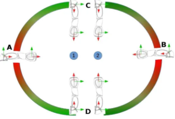
Fig. 1. NAO arm pointing toward objects1and2from positions A to D. Pointing Ambiguity: Positions A and B are ambiguous (both objects 1 and 2 lie alongside the line corresponding to a pointing gesture), whereas C and D are unambiguous (objects 1 and 2 do not lie along the imaginary line related to the pointing gesture).
To address the issue on the GA’s side, we propose a rigorous approach to overcome ambiguities in pointing. In that trail of thought, a model of optimal pointing with respect to the GA’s pose is established and best pointing poses are identified, taking into account the position distribution of objects in the environ-ment. Furthermore, a planner for choosing the pointing pose is developed that minimizes the expected time required for a successful gesture based anchoring.
From the OA’s point of view, we present a pointing gesture perception and the pointed object recognition system. The per-ception performance is modeled quantitatively to determine best gesture observation poses. The model includes both the success rate of gesture recognition as well as the overlap between the fields of view (FOV) of the two agents. The model is used to op-timize the gesture observation pose by taking additionally into account the travel time required by OA to reach each pose.
Through the anchoring process, the two agents end up ob-taining the same identities (symbolic names) for the objects of interest even though GA and OA utilize different object rep-resentations, which are previously trained models for GA and online built models for OA. In the following, we first discuss the individual development of GA and OA. Then, we moving on toward the developed anchoring system.
IV. GESTUREEXECUTION
Pointing gestures are especially valuable in crowded scenes where multiple hypothetical objects matches are present. How-ever, in such scenes the pointing gestures can easily become in-trinsically ambiguous. For example, ambiguity is present when multiple objects lie along the imaginary line corresponding to a pointing gesture as depicted in Fig. 1.
The pointing gesture itself can also be inaccurate. Imperfect calibration of the GA, uncertainty in estimation of object loca-tion, and mechanical accuracy of the GA among other factors limit the accuracy of the gestures. Even if a pointing direc-tion is not ambiguous, small errors in the pointing direcdirec-tion detected by the observer can cause the gesture to fail. Such er-rors may results from inaccuracies in actuator’s positioning, as
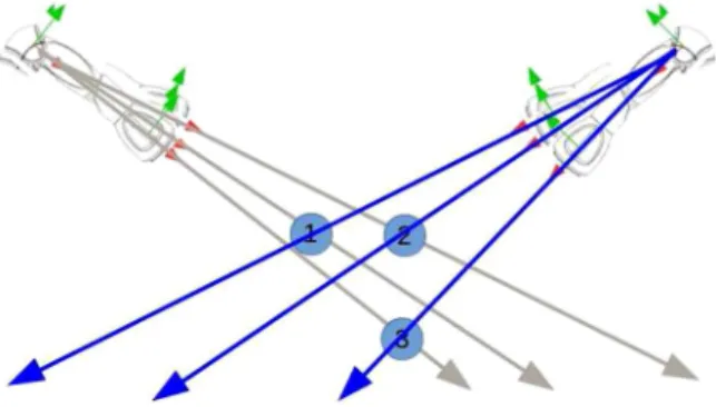
Fig. 2. NAO arm pointing toward objects 1 to 3 from left and right. Inaccura-cies in actuator’s positioning may cause uncertainty to point toward object 1 or 3 from left side. It can be avoided if pointing is executed from the right side.
demonstrated in Fig. 2, where pointing at object 3 from right would be significantly less ambiguous than pointing from the left side.
Moreover, the observation of the gesture can be inaccurate. The latter inaccuracies expand the regions were pointing is am-biguous. The detection of the correct target depends not only on the accuracy of the OA but also on the intrinsic ambiguity of the used pointing gesture. If the inaccuracy of detection is as-sumed to be isotropic, the pointing actions can, thus, be planned without accurate knowledge of the OA.
The pointing process can be outlined as follows: After receiv-ing a request to point at an object of interest from the OA, the GA performs the following tasks:
1) detects all known objects and computes their 3-D positions using a geometric approach;
2) determines a path to optimal pointing location taking into account required time for motion and success probability of each location; and
3) executes the pointing gesture. A. View-Invariant 2-D Object Detection
For completeness, we review here the 2-D object detection method used by the GA. The detection is based on deformable part models (DPMs) that are among the most successful and popular approaches for object detection and pose estimation [39]–[41]. A DPM consists of several object parts and pairwise constraints between them. Thereby, they combine the visual appearance of object parts and their spatial configuration. Such a model can be described as a score function
S(x) = i∈N U(xi) + i,j∈E P(xi, xj). (1)
The unary termU(xi)assesses how well partifits in position
xiin the image. The pairwise termP(xi, xj)takes into account
the position of partsiandjrelative to each other.
As the unary term, we use a scalar product of histogram-of-Gaussian (HOG) features [42], [43]. The pairwise term is
Pi,j(xi, xj) =−(xi−xj −μi,j)TIi,j(xi−xj −μi,j) ∀(i, j)∈E (2)
where the model parameters μi,j andIi,j describe the ideal
distancexi−xj and precision of the distance, respectively.
We use the generalized distance transform algorithm [44] to find maxima of the score function. To account for different view-points we train a small number of DPM models from distinct viewpoints. We optimize every viewpoint specific model sepa-rately, yielding a number of 2-D coordinates, accompanied by their scores. Then, the object proposal with the highest score is the object we sought.
The learning process requires a few hours per object model. Once the model is trained, detection takes about 0.1 s. To extract 3-D coordinates of the detected objects for pointing, intersec-tion of the object view vector and a known supporting plane is determined [25].
The execution of pointing gesture requires the 3-D coordi-nates of the object’s centroid are known. However, the algo-rithm described above outputs the objects centroids along with enclosed bounding box in image coordinates. Therefore, to ex-tract 3-D coordinates of the detected objects, a vector (line) is drawn from the robot camera origin to the centroid of the de-tected object. Assuming that the objects are placed on a known supporting surface, we then extract the 3-D position of the object as the intersection of the vector and the surface [25].
B. Pointing Accuracy Model
Successful pointing requires the gesturing location to be un-ambiguous. Any agents acting as a GA requires to measure the success of pointing gesture execution from a particular loca-tion. Therefore, we utilized the pointing probabilistic model pre-sented in our previous work [25], that gives the success measure within the robot’s workspace. This model utilizes Von Mises– Fisher (VMF) distribution and is given by
G AP i(s|xk) =Pi(κ) = Pi,i(κ) n j=1Pi,j(κ) = n exp(κ) j=1exp(κcosθi,j)
(3) whereθi,j is the angle between the vectors toward the ith
(tar-geted) and jth objects. The scalar concentration parameter κ defines how concentrated the distribution is around the mean. For details of this model please see [25].
In our earlier work [25], we used (3) directly and chose the pointing position as the one maximizing (3), determined by exhaustive search. However, there are often many approximately equally good positions but some of those are easier to reach than others. In the following, we extend the optimization to minimize the time to perform a successful pointing gesture.
C. Dynamic Gesture Planning
The first part of the proposed planning framework had to minimize the expected time to perform successful pointing from positionxk. this is achieved by modeling the total time as
wheretmotion(xk)is the time required to relocate to a position
andtpoint(xk)is the time it takes to execute the pointing gesture,
including the time to first, orient toward target, second, detect the object, and third, perform any relative arm movements. The last term describes the time required for all subsequent pointing attemptstrestin case the first attempt is unsuccessful with prob-abilityGAP
i(¬s|xk)≡1−GAPi(s|xk). The time required for
motion is furthermore expanded as
tmotion(xk) =ttrans(xk) +trot(xk) (5)
where the first term describes the time required to move to the position and the second one to orient the GA toward the target once the position is reached. For the sake of clarity here, we need to emphasize that time costs do not represent actual absolute timing quantities but reflect times required with a particular velocity.
To evaluate the expected time for subsequent pointing at-tempts, we make the simplifying assumption that the likelihood of a pointing position is determined solely by its success rate determined by (3). The expected movement cost can then be approximated using tavg-mot= N k=1GAPi(s|xk)tmotion(xk) N k=1GAPi(s|xk) . (6)
We can also calculate the average probability of failure over all positions asGAP
avg(¬s) = 1/N
kGAP(¬s|xk). Using this
average probability, the number of required attempts until the first success can be computed as the limit of the geometric series as navg= ∞ i=1 (GAP avg(¬s))i= 1 1−GAP avg(¬s) = 1 1−kGAP(¬s|xk) N . (7)
The expected time for subsequent pointing attemptstrestis then trest= tavg-mot 1− N k=1GAPi(¬s|xk) N . (8)
To implement planning using the above, we first calculate a static success probability map for all pointing positions in a grid using (3). Then, optimal trajectories from the starting position to all grid locations are determined using the A-star algorithm, producing the motion costs. The expected motion cost after a failure is then determined (it is important to note that this does not depend on the chosen pointing position). Finally, the expected total costs (time) are determined according to (4) for each grid location and the one with the smallest is chosen.
V. GESTUREOBSERVATION
Gesture observation success depends on the pose of the OA with respect to the GA. Moreover, the movement of the OA to a particular position requires time. In this section, we present how to minimize the expected time required for a successful
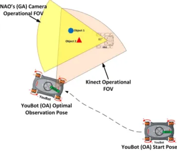
Fig. 3. Optimization of gesture observation. The OA (YouBot) has to move to a pose and orient its perceptual sensor (e.g., Kinect) to achieve maximum visibility of GAs (NAO) pointing arm and of any pointed objects.
observation, following an approach similar to the gesturing in the previous section. This paper is based on our previously developed pointing gesture detection [26] and the probabilistic target object detection method [45].
As an overview, consider the scenario presented in Fig. 3, where the OA initially located in the bottom right corner needs to anchor a representation for an object only known to the GA. After GA is ready to point, it broadcasts a signal signifying this. At this moment, the OA needs to move in a location that mini-mizes the expected time required until a successful observation of the gesture. The observation can fail in two ways: If the rela-tive pose between GA and OA is unsuitable, the OA may fail to observe the gesture altogether. This happens, for example, when the pointing arm is occluded by the body of the GA. Second, the target object may be outside the field of the view of the OA, also causing a failure. The minimization needs to consider then three factors: the probability of successful observation of the gesture from a particular pose, the degree of overlap of FOV of the agents, and the time required to move to a pose. The optimal observation pose can then be chosen, as illustrated by the OA motion in Fig. 3. To consider the above-mentioned fac-tors, we assume that the relative pose between the agents can be estimated by the OA.
The probability of successful observation can be defined as P(D∧O|¯Θ) =P(D|¯Θ)P(O|¯Θ) (9) where D and O are binary variables representing successful gesture detection and object presence in the overlapping FOV, respectively.¯Θdenotes the pose of the OA.DandOare assumed to be independent.
Next, we continue by reviewing the observation method. We then present how to model the gesture detection performance and the FOV overlap. This section concludes by describing how the components can be used to minimize the expected total time.
A. Pointing Gesture and Target Object Detection Using RGB-D
Gesture and target objection detection are based on a previ-ously developed system as reported in [26] and [45]. The system uses a Kinect RGB-D sensor and the detection algorithms are implemented underROS utilizing Point Cloud Library. The ap-proach is divided into following three components, which are responsible for
1) detecting and tracking pointing gestures;
2) segmenting the observed environment into potential ob-jects; and
3) detecting the pointed object by combining results from the two first components.
GA and OA are synchronized when a deictic gesture starts to avoid misdetections caused by other moving objects in the scene.
B. Modeling of Gesture Detection Performance
The success probability of gesture detection with respect to relative pose between OA and GAP(D|¯Θ)needs to be modeled in order to use it in the optimization. Because the relationship between the relative pose and success is complex, we propose to use a nonparametric model, namely a Gaussian process (GP) [46]. The GP is parameterized according to distancedbetween the agents and view directionαaround the GA. The kernel func-tion of the GP is squared exponential with automatic relevance determination K( ¯Θi,¯Θj) =e− ¯ ΘT iL2 ¯Θj 2 (10)
where ¯Θ≡(d, α)T and L≡diag(l
d, lα)are a matrix of the
length scale parameters. To predict the binary variable (success), the cumulative Gaussian
z −∞1/
√
2πe−x2/2dx (11) is used as the likelihood function, to map the GP outputzto the
[0,1]range.
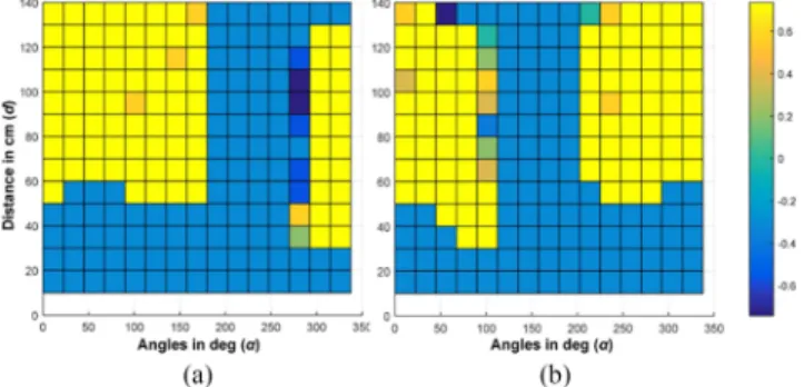
The GP was built using experimental data. Gesturing by GA was observed from different distances in range 10–140 cm ev-ery 10 cm and viewing directions evev-ery 22.5◦(see Fig. 4). For each distance-direction combination, ten trials were made. The success of gesture detection was determined manually as a bi-nary value. The experiment was repeated separately for both arms. Altogether 4480 experimental trials were collected. The resulting data are illustrated in Fig. 5. The failures in a sector are due to self-occlusion by the GA.
Fig. 6 shows plots of the GP output constructed based on the experimental trials for different viewing directions and dis-tances. The two plots correspond to the right and left arm be-ing used for the pointbe-ing and the approximate mirror symme-try of the plots illustrates the different direction of occlusion. The length scale was estimated using maximum likelihood. The model fits the data well while also allowing interpolation.
Fig. 4. Experimental setup for obtaining the probabilistic model for
P(D|d, α).
Fig. 5. Data for the GP model on pointing success for left and right arms. (a) and (c) as well as (b) and (d) are different representations of the same experimental data. (a) Focuses on the observation distances between OA and GA’s right-arm gesturing action. (c) Demonstrates GA orientations with respect to OA. (b) and (d) data collected for GA’s left-arm gesturing action and are antisymmetric to (a) and (c), respectively. (a) Right Arm Detection Values. (b) Left Arm Detection Values. (c) Right Hand Pointing Observations. (d) Left Hand Pointing Observations.
Fig. 6. Modeled Gesture detection probability for different distances and orientations. These tables are obtained using the GPs for machine learning (GPML) package in MATLAB. The results are directly related to the data from Fig. 5. (a) GPML Output for Right Arm Pointing. (b) GPML Output for Left Arm Pointing.
Fig. 7. Four FOV overlap scenarios between NAO camera and Kinect sensor on YouBot. (a) A Bad Overlap. (b) An overlap with Occlusion. (c) A Good Overlap. (d) A Very Good Overlap.
C. Modeling of FOV Overlap
The overlap between the agents’ FOVs depends nontrivially on their relative poses. This is illustrated in Fig. 7. In Fig. 7(c) and (d), the overlap is good. In contrast, in Fig. 7(a), there is only minimal overlap. In Fig. 7(b), the overlap is large but the OA is behind the GA, making this position good in sense of overlap but bad in the view of the gesture detection performance.
We model the probability of having the pointed object in OA’s FOVP(O|¯Θ)by calculating the proportion of GA’s FOV that is covered by OA’s FOV. For this scenario the GA’s FOV area is defined by 61◦ angle with 1.5 m range and the OA’s FOV area by 57◦ angle with 1.5 m range. The results were calculated offline and stored in a 40 by 40 grid-table with squared cells of 0.15 m resolution. During the modeling pro-cedure, GA remains stationary in the center of the grid (with 0◦ orientation toward the positive x-axis) and the OA sequen-tially assumes all cell positions (cell(i, j)with0≥i, j≥40). In each of these cells, OA performs a full revolution on its z-axis with resolution of 1◦and the OA–GA FOV overlaps are calculated. Finally, for each cell we obtain the maximum over-lap with respect to OA’s orientations as shown in the equation below
P(O|¯Θcell) = max(P(O|i, j,0◦), . . . , P(O|i, j,360◦)) (12) where the pose is ¯Θcell≡(i, j, β)T andβis the angle that max-imizesP(O|¯Θ)withβ=α.
The calculated maximum overlaps are shown in Fig. 8 (left). The figure illustrates the multimodal nature of the overlap as local maxima appear in front right, front left, and exactly behind the GA. It is important to note that also orientation of the OA is optimized in the process. Optimal orientations (β) for each position are shown Fig. 8 (right). Noticing the detail in the figure, the complex nature of the FOV overlap is apparent.
Fig. 8. These two pictures assume that the GA is located in the middle of the grid facing toward the positive x-axis. (left) probability of overlap, with lighter cells representing higher propabilityP(O|¯Θ); (right) optimal orientations (β) of the OA, with its initial orientation (0◦) directed toward the positive x-axis. The lighter the color inside that grid the more the robot has turned CCW. (a) Quantitative Distribution of overlapping FOVs. (b) Optimal Orientation Detecting the Right Arm.
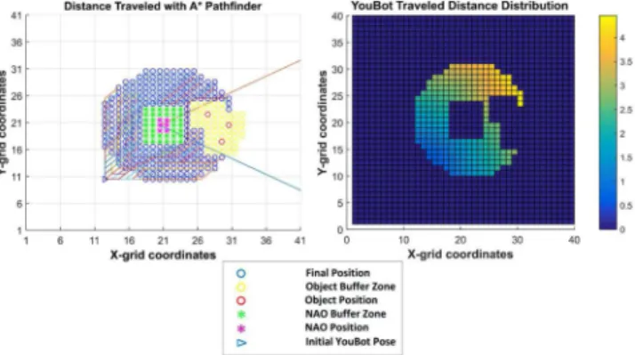
Fig. 9. (left) A-Star algorithm for optimally planning a path to any valid observation position; (right) Distribution of traversed distances (in meters) by the OA to reach any available observation positions.
D. Optimization of Observation
Similar to gesturing, we aim to minimize the expected time, and thus, the energy, required for an OA to reach an optimal observation pose relative to GA pose and to the position of the pointed objects. The implementation, follow the general idea presented in Section IV-C. Repeating the model from (4) for convenience
ttotal(xk) = (tmotion(xk) +tpoint(xk)) +OAPi(¬s|xk)trest (13) where now the success is determined by the FOV and ges-ture detection,OAP(¬s|x) =P(¬D∨ ¬O|¯Θ),¯Θbeing the po-lar representation of the relative posex. Rest of the formulas (5)–(8) remain the same. The motion costs described by (5) are computed with A-star taking into account obstacles, such as other agents and objects in the environment.
Fig. 9 explains the distribution of the motion costs, when the OA traverses from a starting pose to each and every potential ob-serving pose. These potential poses satisfy the conditionP(D∧ O|¯Θ)>0. Each traveled distance is directly proportional to the time required for the OA to reach an optimal pose, multiplied by its velocity (dmotion(xk) =v(xk)tmotion(xk)). Here, the OA
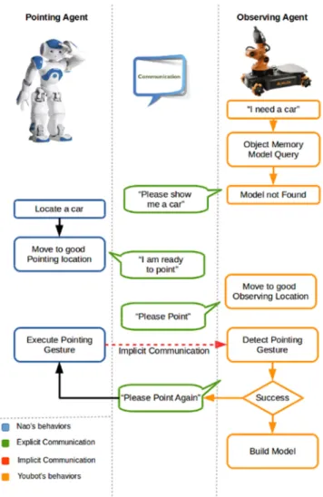
Fig. 10. Anchoring process: When internal representation not found. (Here, blue and orange boxes indicates the internal processing of GA and OA; explicit communications are shown in green boxes and implicit communications are shown with red arrow).
by a buffer no-go area (green stars), is placed at the center of the grid facing toward the positive X-axis. Inside GA’s vicinity (red and blue lines) we have placed three target objects, which are again surrounded by a yellow buffer no-go area. Running the A-star algorithm we extract all optimal translations to reach the potential observing locations (blue circles) and the associated traveled distances (meters) are recorded in Fig. 9.
VI. ANCHORINGPROCESS
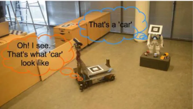
Fig. 10 shows the anchoring process exemplified using two robots, GA (a NAO, on the left) and OA (a YouBot, on the right). OA starts with a task requiring the object “car.” It first checks its internal object representation database for a perceptual object model associated with the symbol “car.” Lacking a perceptual (anchored) model, it transmits a request for the other robot to show the “car” object, transmitting the symbolic name of the required object.
GA (NAO in the example) receives the request and begins a perceptual process for locating the object. After locating the object referred by the received symbol (car), GA plans a path to
Fig. 11. Use of anchored representations when internal representation exist in OA’s memory.
a location that is good for pointing. For details of these, please see Section IV. After arriving in a good pointing location, GA transmits a confirmation message that it is ready to point.
OA (YouBot) receives the confirmation and plans a path to relocate to suitable location for observing the pointing gesture as described in Section V. Arriving to the observation location, it transmits a request to GA to execute the pointing gesture. Simultaneously, it begins the observation process for the gesture. GA (NAO) receives the request and executes the pointing ges-ture, as presented in Section IV. Simultaneously, OA observes the gesture and detects the object being pointed at, as described in Section V, resulting in a point cloud segment corresponding to the correct object. If OA is not successful, it transmits a re-quest to repeat the pointing gesture. After success, OA builds an internal model/representation of the object associated with the symbol “car,” as presented in Section VI-B.
After a symbol has been anchored, the built internal model can be used in subsequent tasks where the object is required. Fig. 11 shows the same scenario of a robot needing the object “car,” with the difference that the robot already has the internal perceptual model. The internal memory query is successful and the robot subsequently executes an object detection method with the corresponding model. If the object detection fails, the robot can fall back on requesting help from other agents. In that case, the anchoring process described in Fig. 10 would be executed and the robot would update/generate another perceptual model for the same symbol, generalizing the meaning of the symbol. A. Anchoring Logic
The anchoring process can be triggered automatically when needed, that is, when the anchoring of a particular symbol is required by a particular agent. For example, OA needs object X. The pick up action requires detecting Object X, which in turn requires the object to be anchored. The anchoring in turn requires another agent (GA) that has the object already anchored and both agents located in suitable places.
We assume that the agents share the symbolic domain and task knowledge. The sharing can be performed using low-bandwidth explicit communication, such as wireless link.
The domain knowledge mentioned above can be described in a planning language, such as PDDL, as follows:
(:types obj robot) (:predicates
(has-x ?x - obj ?y - robot)
(object-anchored ?x - obj ?y - robot) (object-detected ?x - obj ?y - robot) (ready-to-point ?x - obj ?y - robot) (readytoobserve ?x obj ?y
-robot))
(:action pick-up :parameters (?x - obj ?y - robot)
:precondition (object-anchored ?x ?y) :effect (has-x ?x ?y))
(:action point :parameters (?x obj ?y -robot ?z - -robot)
:precondition (and (ready-to-point ?x ?y) (ready-to-observe ?x ?z))
:effect (object-anchored ?x ?z)) (:action move-to-pointing :parameters
(?x - obj ?y - robot)
:precondition (object-x-detected-for-y ?x ?(object-x-detected-for-y)
:effect (ready-to-point-at-x ?x ?y)) (:action move-to-observation :parameters
(?x - obj ?y - robot ?z - robot)
:precondition (ready-to-point ?x ?z) :effect (ready-to-observe ?x ?y)) (:action detectobject :parameters (?x
-obj ?y - robot)
:precondition (object-anchored ?x ?y) :effect (object-detected ?x ?y))
The task of OA getting a “car” can then be described as
(:objects car - object GA OA - robot) (:init (object-anchored car GA)) (:goal (robot-has car OA))
Solving the planning problem results in the following plan:
(detect-object car GA) (move-to-pointing car GA)
(move-to-observation car OA GA) (point car GA OA)
(pick-up car OA)
which will then be executed synchronously on both agents. To solve the planning problem, we used a standard search based planner.
B. Implementation
Most of the processes shown in Figs. 10 and 11 have already been explained in the earlier chapters. The exceptions are the communication link, and object modeling and detection per-formed after anchoring. They will be described here briefly for completeness.
1) Communication Link: The communication link handles the explicit communication between the agents using prede-fined messages. The messages can be divided into requests and responses indicating a success or failure of a particular process. Requests can also include a parameter, which in the above-mentioned example indicates the symbol corresponding to the target object. The explicit communication link was implemented using ROS as communications middleware. All agents connect to a shared ROS core in order to communicate with each other. 2) Object Modeling and Detection: Object modeling com-ponent builds a perceptual model of a detected and segmented object. The implementation can use any available modeling method that is compatible with the robot’s sensors. For our demonstration set up, YouBot has an RGB-D sensor that cap-tures the point cloud corresponding to the object. For perception purposes, the object is modeled using a color histogram. To ob-tain some invariance against varying lighting conditions, a nor-malized RGB chromaticity space is used. That is, the(R, G, B) triplet is converted to(r, g)chromaticity space using
r= R
R+G+B g= G
R+G+B. (14) Then, a 2-D(r, g)histogramh(r, g)is built. The histogram is then normalized to unit volume, so thatrgh(r, g) = 1.
Object detection on YouBot is performed in two steps. First, all objects in the working area are segmented using the known ground plane. Second, chromaticity histograms of point cloud segments are matched usingL2-norm against the available mod-els. If the distance is greater than a thresholdθ, the matching fails and a detection failure is reported.
VII. EXPERIMENTS ANDRESULTS
This section presents a number of simulated and real exper-iments on anchoring scenarios. The validity of the proposed approach is first verified in simulation by individually examin-ing the proposed optimization techniques for both the GA and OA. Next, a real robot scenario demonstrates the actual imple-mentation of the described subsystems (acting and observing) in a unified object anchoring framework, where a NAO robot acts as a GA and a YouBot platform as the OA.
A. Simulation of Gesture Planning Model
In this section, we present the simulation of gesture plan-ning, optimization and execution, demonstrating the behavior of pointing probability model for different locations of the
Fig. 12. Pointing success probability from different positions. Crosses denote objects and red circle the target object.
Fig. 13. (left) A-star paths. (right) time cost map.
targeted object, using (3). Moreover, it also demonstrate the behavior of dynamic planner module discussed in section. For the purpose of simulation, it is assumed that all objects are within the field of view of GA. The object detection algorithm does not take occlusions into account, therefore, it is further assumed that none of the objects is occluded, i.e., all objects in the scene were detected by the GA.
For simulation set up, we consider a work-space of 4×4 m2 dimensions with the grid resolution of 0.1 m. Five objects were placed in the workspace at locations marked with crosses in Fig. 12.
The Fig. 12 shows the success probability maps for the execu-tion of pointing gesture for different locaexecu-tions of target objects (marked with red circles). It can be seen from the figure that with different location of the targeted object the shape of the success map is different. Due to the embodiment of the GA, it is possible to point over the top of other distracting objects as predicted by the success probability model.
The success probability model of (3) predicts several loca-tions to be approximately equally good as seen in Fig. 12. This emphasizes the importance of taking into account the cost of motion as well as possible new tries, in determining an optimal pointing position.
Next, tmotion(xk) was calculated using A-Star, assuming
agent’s linear and angular velocities to be 0.4 m/s and 0.1 rad/s, respectively. The planned paths and motion cost maps to reach each grid location are shown in Fig. 13. In this figure, the agent’s starting pose is marked with the green arrow. It may be noted that objects are inflated to a safe distance to avoid collision. More-over, the location of target object is not required for calculation oftmotion(xk).
After reaching a particular location, the target orientation computed by the A-Star algorithm is not necessarily oriented toward the object of interest. This orientation costtpointdepends
Fig. 14. Time(tpoint)required to orient toward target, object detection, and
pointing gesture execution from positions(xk).
Fig. 15. Optimum positions for pointing gesture execution along with planned path for selected objects of interest.
on the location of the target object. The time costs tpoint for adjusting orientation are shown in Fig. 14. This figure shows the final orientation cost for the targeted object marked in red. It can be seen from this figure that the final orientation of GA depends on the location of the object of interest relative to the grid location.
Finally, the time costs according to the full model defined by (4) are presented in Fig. 15. The starting and optimal poses of GA are shown with green and red arrows, respectively. It should be noted that the optimum pose depends not only on the relative location of target object but also on the relative location of distracting objects as well as GA’s starting pose. In center and right cases the optimum is not unique, that is, there exists an equally good optimum on the south side of the objects due to the symmetric setup. Moreover, it is interesting to note how the choice of the target object significantly changes the cost map so that in some configurations, such as the center one, good pointing locations are rather limited while in others, such as the right one, there are more reasonably good options.
B. Simulation of Gesture Observation
In this section, we present a number of simulation experiments to study the behavior of the optimization of gesture observation. The GA is a NAO humanoid while the OA is a YouBot. To study the behavior, the NAO will use either the left or the right arm for pointing.
Fig. 16 presents the probability distribution for gesture ob-servation successP(D∧O|¯Θ), for pointing with right and left arms. The graphs are obtained by combining the probability distributions of detection success P(D|¯Θ) and FOV overlap P(O|¯Θ). Thus, when the GA (NAO) points with its right or left arm, the joint probability distributionP(D∧O|¯Θ)designates the front right or front left of the GA position, respectively, as the best possible solution. This is a reasonable choice since from
Fig. 16. 2-D grid of optimal position probability of detection distribution (P(D∧O|¯Θ)) when OA observes GA pointing with: (a) right arm and (b) left arm.
Fig. 17. Four experimental cases where OA starts from different poses.
this areas, the observer has the best visibility of the pointing action plus a wide area of FOV overlap. However, the com-plex and multimodal nature of the distributions demonstrates that the consideration of the movement cost in optimization has potential to decrease the required effort.
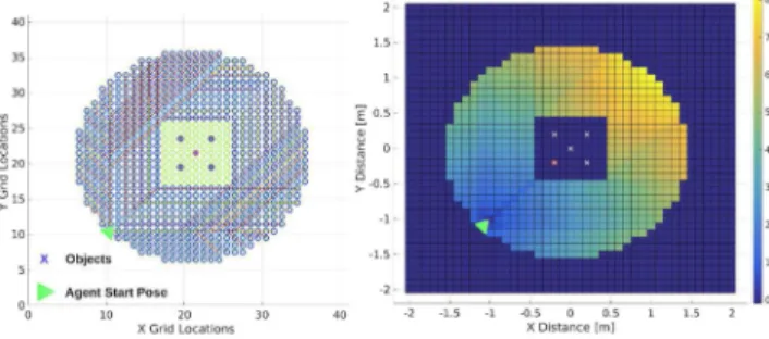
Fig. 17 describes the four different scenarios where the GA (purple star) was always placed at the center of the grid, facing toward the positive X-axis, and was surrounded by a no-go buffer zone (green stars). The grid was composed by rectangular cells with 0.15 m resolution and had a size of 6×6 m2. Three objects were placed inside the visual field of the GA, which is defined by the red-blue lines intersecting the origin of GA’s FOV and at an angle of 61◦. The objects (red circles) occupy a single grid cell each. The area around the objects was marked as a no-go area (yellow circles) to avoid possible collisions with the moving observer. The YouBot OA started its run from four different locations, shown in Fig. 17: a) top-left for Case 1, (b) bottom-left for Case 2, (c) bottom-right for Case 3, and (d) top-right for Case 4. For each case, the OA utilized the optimal paths, to reach all active cells withP(D∧O|¯Θ)>0in Fig. 17.
Figs. 18 and 19 show the total coststtotalwhen GA points with left/right arm, for each of the four starting positions. The
Fig. 18. OA time cost (second) distributions for the four different initial positions, when GA robot is pointing with the right arm.
Fig. 19. OA time cost (second) distributions for the four different initial positions, when GA robot is pointing with the left arm.
best observation positions for OA lie in the right or front-left of the GA. However, when considering the total expected time, the optimal positions vary significantly and all cases have multiple local minima. This is because of the complexity of the observation success model P(D∧O|¯Θ), combined with the movement costs. Therefore, in many cases the optimal pointing location is not the one which maximizes the observation success probability.
C. Anchoring Process
The real robot anchoring scenario is divided into two stages. The first stage is related to the actions taken by the GA (NAO), in order to optimize its position relative to the available ob-jects of interest. The second stage is related to the OA (YouBot) actions for optimizing its observation pose relative to the GA, and anchor the detected pointed object. To localize in space and, thus, extract the required relative position and orientation
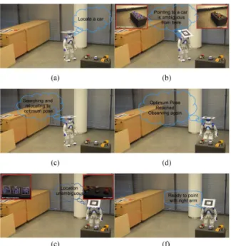
Fig. 20. GA’s behaviors to anchor an object of interest. (a) Detecting objects. (b) Ambigous location. (c) Planning. (d) Relocating. (e) Unambigous detection. (f) Explicit communication.
between the two participating robotic agents, an indoor posi-tioning system (IPS) was established. It may be noted that this IPS is only used for navigation and localization. It relied on AR-markers mounted on the top of the two agents, which were tracked by a number of ceiling cameras. Two high frame rate cameras (PlayStation Eye with 640×480 resolution at 60 Hz) were utilized covering an area of 2×2 m2.
1) Gesturing: Prior to the experiment, the GA was trained to detect several different classes of objects from a 2-D camera image using the algorithm described in Section IV-A. The IPS described earlier was used for localization because the GA does not have reliable means of obstacle detection. In path planning, object positions were inflated to avoid collisions. A prior map of the workspace constructed by the OA was utilized for path planning. The parameterκof the pointing accuracy model was estimated experimentally as 65.
The GA’s behaviors are depicted in Fig. 20. Initially GA waits for a request from OA. After the request (with an object tag) is received [see Fig. 20(a)], the GA searches for the known objects within the field of view using the algorithm described in Section IV-A. Fig. 20(b) shows camera image (top right) and the result of detection algorithm (top left) of all known objects. It then calculates their relative locations needed to create a probability map for the requested object. From the current pose, it would be difficult for the GA to anchor the pointing gesture to a single targeted object. Therefore, it is important to relocate to a better position to execute a pointing gesture.
From the list of detected objects, the GA selects an object with matching object tag as the target object (here the selected target object is a red toy car). Once the requested object is located, GA first creates a static success probability map using the model presented in (3). Then, calculates the shortest path
Fig. 21. OA’s behaviors to anchor the object of interest. (a) Planning. (b) Observing pose. (c) Explicit communication. (d) Implicit communication.
and their path costs to every grid location using A-Star. This in turn creates a motion cost map (tmotion) to reach to every grid location along with the end path orientation. Using the grid locations and precalculated location of the targeted object, the desired orientation is extracted for all grid locations. Then, the tpointcost map of time required to reorient from end orientation of path toward the targeted orientation is constructed.
Using the probability mapPi(κ), cost map(tmotion), andtpoint, the GA then creates a map ofttotal(xk)using (4). The location
for whichttotal(xk)is minimum is the desired optimum location.
GA then uses the planned path to reach the desired optimum pose.
After reaching the desired optimum pose, the GA once again detects the objects. Fig. 20(e) shows camera image (top right) and the result of detection algorithm (top left) of all known objects after reaching the optimum pose. In the figure, it can also be seen that it is unambiguous to point to the targeted object from this location. However, before anchoring to the ob-ject using the pointing gesture, GA needs to make sure that the OA is observing. Therefore, it sends a “I am ready to point” signal to OA and waits for a synchronization signal from the OA.
2) Gesture Observation: OA behavior is shown in Fig. 21. OA action begins when the GA broadcasts the “ready to point” signal specifying also the pointing arm [ see Fig. 20(f)]. At that time, the OA is stationed idle at a starting location. After receiv-ing the signal, OA determines the total cost takreceiv-ing into account GA’s position and the observation models. The minimum cost location is then chosen.
To move to the optimal pose [ see Fig. 21(b)], a map pre-viously constructed with the on-board Hokyo lidar was used. Fig. 21(c) and (d) illustrates the implicit–explicit negotiation process between the GA and the OA, in order to anchor the object of interest. At that time, the OA first transmits an explicit “please point” message to GA and immediately activates the gesture detection and object recognition algorithm as presented in Section V. Next, the implicit communication using gestures takes place, where GA points to an object of its selection and the OA recognizes this action and localizes the detected object
Fig. 22. Pointing success probability to anchor targeted object from different positions.
in its own frame of reference [see Fig. 21(d)]. If it fails to suc-ceed, it explicitly instructs the GA to repeat the gesture. The number of retries was set for this experiment to three. Failing to successfully localize the pointed object of interest after three trials, will initiate a replanning process where GA and OA will recalculate their best optimal position matrices and relocate to their newly selected poses to repeat the implicit communication stage.
3) Object Anchoring: The final stage of this experiment is to anchor the object of interest between the two robotic agents. As is the case in the presented work, two heterogeneous robotic agents with different embodiments and different sensor char-acteristics, perceive the environment differently and, thus, they store different models for any detected objects. The goal of an-choring objects between two agents using gestures is to provide the two agents with common knowledge of their space minimiz-ing, at the same time, the explicit communication requirements. Fig. 22 illustrates the final stage of the presented experiment where, after pointing to an object, the GA explicitly broadcasts a “a car” message. Having detected the pointing gesture and the pointed object, the OA extracts using a Kinect sensor the cluster of points representing the object and builds a model for future recognition purposes as described in Section VI-B2.
VIII. DISCUSSIONS
The proposed framework is based on the following assumptions.
1) The GA must have at least an arm/appendage capable to perform gesturing actions.
2) Agents are mobile.
3) Agents must have some means to perceive objects in their environment.
4) Agents are capable of observing the relative pose between them.
5) The object identities (symbols) can be transmitted using some communications channel.
The requirements are easily met in almost all RRI scenarios, with the possible exception of the requirement for an arm. Nev-ertheless, the primary use scenario for the approach is mobile manipulation in which all of the assumptions are true.
Assuming the above-mentioned requirements are satisfied, the approach can be configured for any robot. The required pa-rameters for planning of pointing actions are relatively easy to calibrate, as they relate to the pointing agent’s speed of mo-tion and the accuracy of pointing acmo-tions described by a single parameter. The ease stems from the fact that the planning ad-dresses primarily the ambiguity of pointing that does not depend on the pointing agent. The parameters required for optimizing observation relate to speed of motion and the performance of the pointing detection method that depends, e.g., on occlusions. The latter can not be easily modeled, and thus, a data-driven approach was proposed for the modeling. The calibration re-quires, thus, more effort if optimality of the planning is desired, with sparser data likely resulting in nonoptimal results. Nev-ertheless, the iterative nature of the approach with replanning triggered upon failure will allow successful anchoring even in this case.
Regarding the runtime performance of the proposed algo-rithm, the system is composed by: first, the detection com-ponents, which includes the deployed object detection (DMP, GTD, HOG) and gesture tracking algorithms ([26] and [45]) and, second, the pose optimization component using the A-Star algorithm. In the first category, the gesture tracking algorithm, as reported in [26], performs at an overall≈3.3 Hz update rate. For pose optimization, both the OA and GA use the A-Star al-gorithm to obtain thetmotion(xk)distribution (6) in real time.
The time complexity of A-Star depends on the heuristic. In the worst case of an unbounded search space, the number of nodes expanded is exponential in the depth of the solution (the short-est path)d:O(bd), wherebis the branching factor (the average
number of successors per state). This assumes that a goal state exists at all, and is reachable from the start state; if it is not, and the state space is infinite, the algorithm will not terminate. In the experiment, the algorithm took less than a second to calculate the optimal path.
During the offline modeling process, the designers exe-cute a number of experiments or offline simulations to fine tune models, such as the probability of FOV overlapP(O|¯Θ) (see Fig. 8) and the probability of gesture detectionP(D|¯Θ) (see Figs. 5 and 6). During that offline procedure the mentioned pointing accuracy model VMF distribution and the GP [46] were utilized. Computationally the training of the 2-D object detec-tion algorithm (see Secdetec-tion IV-A) requires a few hours, while fitting the GP models requires less than one minute.
Although the framework has been designed for RRIs, its com-ponents would be applicable to HRI scenarios. In particular, planning of ambiguity free pointing actions could be used when a human requests a robot to point at a particular object (please show me the 5/8 in wrench). Similarly, the planning of obser-vation could be used when a human wants to name a particular object by pointing to it (see, that is the 5/8 in wrench).
IX. CONCLUSION
This paper proposed the use of gestures for object anchor-ing between mobile robotic agents. The proposed methodol-ogy solves the problem of the perceptual mismatch between
heterogeneous agents. That is, it does not require shared sensors or shared internal representations of the objects between the robots. It also minimizes explicit communication (e.g., radio) requirements between the two interacting agents by implicitly using gestures and body language. In the presented scenario, two robotic agents interact with each other trying to anchor an object of interest. An agent with the knowledge about a partic-ular object gestures toward it to transmit the object’s identity to an OA. The proposed approaches minimize the time required for the anchoring, taking into account possibility of failure.
Results from simulations indicate the complex nature of the planning problem in that the spatial cost functions are multi-modal for both gesturing and OAs. Experiments with a physi-cal two-robot system demontrated the validity of the proposed methodology.
The work in this paper was limited to RRI. However, the tack-led problems, for example the ambiguity of pointing gestures, are also present in HRI. The proposed approaches and models are then also applicable when humans and robots communicate by pointing. Experimental study of this aspect is a promising avenue for future work.
REFERENCES
[1] M. M. Louwerse and A. Bangerter, “Focusing attention with deictic ges-tures and linguistic expressions,” in Proc. 27th Annu. Meet. Cogn. Sci.
Soc., 2005, pp. 1331–1336.
[2] S. Coradeschi and A. Saffiotti, “An introduction to the anchoring problem,”
Robot. Auton. Syst., vol. 43, no. 2, pp. 85–96, 2003.
[3] L. Steels and M. Hild, Language Grounding in Robots. Berlin, Germany: Springer, 2012.
[4] K. LeBlanc and and A. Saffiotti, “Cooperative anchoring in heterogeneous multi-robot systems,” in Proc. IEEE Int. Conf. Robot. Automat., 2008, pp. 3308–3314.
[5] P. Vogt, “Perceptual grounding in robots,” in Proc. Eur. Workshop Learn.
Robots, 1997, pp. 126–141.
[6] S. Waldherr, R. Romero, and S. Thrun, “A gesture based interface for human-robot interaction,” Auton. Robots, vol. 9, no. 2, pp. 151–173, 2000. [7] H.-D. Yang, A.-Y. Park, and S.-W. Lee, “Gesture spotting and recognition for human–robot interaction,” Proc. IEEE Trans. Robot., vol. 23, no. 2, pp. 256–270, 2007.
[8] K. Nickel and R. Stiefelhagen, “Visual recognition of pointing gestures for human–robot interaction,” Image Vis. Comput., vol. 25, no. 12, pp. 1875– 1884, 2007.
[9] M. Salem, S. Kopp, I. Wachsmuth, K. Rohlfing, and F. Joublin, “Genera-tion and evalua“Genera-tion of communicative robot gesture,” Int. J. Soc. Robot., vol. 4, no. 2, pp. 201–217, 2012.
[10] L. Perlmutter, E. Kernfeld, and M. Cakmak, “Situated language under-standing with human-like and visualization-based transparency,” in Proc.
Robot., Sci. Syst., 2016, doi:10.15607/RSS.2016.XII.040.
[11] A. Saupp´e and B. Mutlu, “Robot deictics: How gesture and context shape referential commured arrow indicates nication,” in Proc. ACM/IEEE Int.
Conf. Human Robot Interact., 2014, pp. 342–349.
[12] H. Admoni, T. Weng, and B. Scassellati, “Modeling communicative be-haviors for object references in human-robot interaction,” in Proc. IEEE
Int. Conf. Robot. Automat., May 2016, pp. 3352–3359.
[13] C.-M. Huang and B. Mutlu, “Learning-based modeling of multimodal behaviors for humanlike robots,” in Proc. ACM/IEEE Int. Conf. Human
Robot Interact., 2014, pp. 57–64.
[14] T. M. Howard, S. Tellex, and N. Roy, “A natural language planner interface for mobile manipulators,” in Proc. IEEE Int. Conf. Robot. Automat., May 2014, pp. 6652–6659.
[15] T. Kollar, S. Tellex, D. Roy, and N. Roy, “Toward understanding natural language directions,” in Proc. 5th ACM/IEEE Int. Conf. Human Robot
Interact, 2010, pp. 259–266.
[16] P. Jing and G. Yepeng, “Human-computer interaction using pointing ges-ture based on an adaptive virtual touch screen,” Int. J. Signal Process.
Image Process., vol. 6, no. 4, pp. 81–92, 2013.
[17] O. Patsadu, C. Nukoolkit, and B. Watanapa, “Human gesture recognition using kinect camera,” in Proc. IEEE Int. Joint Conf. Comput. Sci. Softw.
Eng., 2012, pp. 28–32.
[18] X. Zabulis, H. Baltzakis, and A. Argyros, “Vision-based hand gesture recognition for human-computer interaction,” Universal Access
Hand-book. LEA, Boca Raton, FL, USA: CRC Press, 2009, pp. 34–1.
[19] M. Sigalas, H. Baltzakis, and P. Trahanias, “Gesture recognition based on arm tracking for human-robot interaction,” in Proc. IEEE/RSJ Int. Conf.
Intell. Robots Syst., 2010, pp. 5424–5429.
[20] T. Axenbeck, M. Bennewitz, S. Behnke, and W. Burgard, “Recognizing complex, parameterized gestures from monocular image sequences,” in
Proc. 8th IEEE-RAS Int. Conf. Humanoid Robots, 2008, pp. 687–692.
[21] M. Bennewitz, F. Faber, D. Joho, M. Schreiber, and S. Behnke, “To-wards a humanoid museum guide robot that interacts with multiple per-sons,” in Proc. IEEE 5th IEEE-RAS Int. Conf. Humanoid Robots, 2005, pp. 418–423.
[22] M. Spranger, M. Loetzsch, and L. Steels, “A perceptual system for lan-guage game experiments,” in Lanlan-guage Grounding in Robots. Berlin, Germany: Springer, 2012, pp. 89–110.
[23] V. V. Hafner and F. Kaplan, “Learning to interpret pointing gestures: Experiments with four-legged autonomous robots,” in Biomimetic
Neu-ral Learning for Intelligent Robots. Berlin, Germany: Springer, 2005,
pp. 225–234.
[24] R. M. Holladay, A. D. Dragan, and S. S. Srinivasa, “Legible robot point-ing,” in Proc. 23rd IEEE Int. Symp. Robot Human Interactive Commun., 2014, pp. 217–223.
[25] K. Gulzar and V. Kyrki, “See what i mean-probabilistic optimization of robot pointing gestures,” in Proc. 15th IEEE-RAS Int. Conf.
Hu-manoid Robots HuHu-manoids, Seoul, South Korea, November 3–5, 2015,
pp. 953–958.
[26] P. Kondaxakis, J. Pajarinen, and V. Kyrki, “Real-time recognition of point-ing gestures for robot to robot interaction,” in Proc. IEEE/RSJ Int. Conf.
Intell. Robots Syst., 2014, pp. 2621–2626.
[27] N. Hofemann, J. Fritsch, and G. Sagerer, “Recognition of deictic gestures with context,” in Pattern Recognition. Berlin, Germany: Springer, 2004, pp. 334–341.
[28] M. Pateraki, H. Baltzakis, and P. Trahanias, “Visual estimation of pointed targets for robot guidance via fusion of face pose and hand orientation,”
Comput. Vis. Image Underst., vol. 120, pp. 1–13, 2014.
[29] Y. Nagai, “Learning to comprehend deictic gestures in robots and human infants,” in Proc. IEEE Int. Workshop Robot Human Interact. Commun., 2005, pp. 217–222.
[30] C. Perez Quintero, R. T. Fomena, A. Shademan, N. Wolleb, T. Dick, and M. Jagersand, “Sepo: Selecting by pointing as an intuitive human-robot command interface,” in Proc. IEEE Int. Conf. Robot. Automat., 2013, pp. 1166–1171.
[31] O. Sugiyama, T. Kanda, M. Imai, H. Ishiguro, and N. Hagita, “Three-layer model for generation and recognition of attention-drawing behavior,” in
Proc. IEEE/RSJ Int. Conf. Intell. Robots Syst., 2006, pp. 5843–5850.
[32] S. Harnad, “The symbol grounding problem,” Physica D, Nonlinear
Phe-nom., vol. 42, no. 1, pp. 335–346, 1990.
[33] L. Steels, “The symbol grounding problem has been solved. So what’s next,” Symbols Embodiment: Debates Meaning Cognition. London, U.K.: Oxford Univ. Press, 2008, pp. 223–244.
[34] T. Belpaeme and S. J. Cowley, “Extending symbol grounding,” Interact.
Stud., vol. 8, no. 1, pp. 1–16, 2007.
[35] J. S. Olier, E. Barakova, C. Regazzoni, and M. Rauterberg, “Re-framing the characteristics of concepts and their relation to learning and cognition in artificial agents,” Cogn. Syst. Res., vol. 44, pp. 50–68, 2017. [36] C. J. Needham, P. E. Santos, D. R. Magee, V. Devin, D. C. Hogg, and A.
G. Cohn, “Protocols from perceptual observations,” Artif. Intell., vol. 167, no. 1, pp. 103–136, 2005.
[37] K. M. MacDorman, “Cognitive robotics. Grounding symbols through sen-sorimotor integration,” J. Robot. Soc. Jpn., vol. 17, no. 1, pp. 20–24, 1999. [38] A. Cangelosi, “Grounding language in action and perception: From cogni-tive agents to humanoid robots,” Phys. Life Rev., vol. 7, no. 2, pp. 139–151, 2010.
[39] P. F. Felzenszwalb, R. B. Girshick, and D. McAllester, “Cascade object detection with deformable part models,” in Proc. IEEE Conf. Comput. Vis.
Pattern Recognit., 2010, pp. 2241–2248.
[40] I. Kokkinos, “Rapid deformable object detection using dual-tree branch-and-bound,” in Proc. Adv. Neural Inf. Process. Syst., 2011, pp. 2681–2689. [41] I. Kokkinos, Accelerating Deformable Part Models With
Branch-and-Bound. Cham, Switzerland: Springer International Publishing, 2016,