STOCKHOLM, SWEDEN 2019
DAVID MARLEVI
Non-invasive imaging for
improved cardiovascular
diagnostics
Shear wave elastography, relative pressure
estimation, and tomographic reconstruction
NON-INVASIVE IMAGING FOR IMPROVED
CARDIOVASCULAR DIAGNOSTICS
Shear wave elastography, relative pressure estimation, and tomographic reconstruction
DAVID MARLEVI
Doctoral Thesis
KTH Royal Institute of Technology
School of Engineering Sciences in Chemistry, Biotechnology and Health Department of Biomedical Engineering and Health Systems
Division of Biomedical Imaging SE-141 52 Huddinge
Karolinska Institutet
Department of Clinical Sciences SE-171 77 Stockholm
Akademisk avhandling som med tillstånd av Kungliga Tekniska Högskolan och Karolinska Institutet framlägges till offentlig granskning för avläggande av teknologie och medicine doktorsexamen fredagen den 20 september 2019 klockan 09:00 i sal T2, Hälsovägen 11C, Kungliga Tekniska Högskolan.
Main supervisor Assoc. Prof. Matilda Larsson
KTH Royal Institute of Technology Stockholm, Sweden
Co-supervisors Prof. Reidar Winter
Karolinska Institutet Stockholm, Sweden Assoc. Prof. Massimiliano Colarieti-Tosti KTH Royal Institute of Technology Stockholm, Sweden
Faculty opponent Prof. Kathryn Nightingale
Duke University Durham, NC, United States of America
Evaluation committee Prof. Ulf Hedin
Karolinska Institutet Stockholm, Sweden Prof. Alistair Young King’s College London London, United Kingdom Assoc. Prof. Paola Nardinocchi Sapienza University of Rome Rome, Italy TRITA-CBH-FOU-2019:38
ISBN 978-91-7873-251-7 Department of Biomedical Engineering and Health Systems KTH Royal Institute of Technology
Department of Clinical Sciences Karolinska Institutet
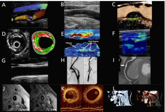
Cover: Shear wave propagation through a carotid AHA type VI plaque
© David Marlevi, 2019
List of publications
This thesis is based on the following eight publications. At the end of this thesis, all publications are provided in their published or prepared manuscript form:
I. Arterial stiffness estimation by shear wave elastography: validation in phantoms with mechanical testing
E. Maksuti, E. Widman, D. Larsson*, M.W. Urban, M. Larsson,
A. Bjällmark
Ultrasound in Medicine & Biology, vol. 42, p. 309-321, 2016
II. Plaque characterization using shear wave elastography – evaluation of differentiability and accuracy using a combined ex-vivo and in-vitro setup
D. Marlevi, E. Maksuti, M.W. Urban, R. Winter, M. Larsson Physics in Medicine & Biology, vol. 63, no. 23, 235008 (17pp), 2018
III. An ex-vivo setup for characterization of atherosclerotic plaque using shear wave elastography and micro-computed
tomography
D. Larsson*, J. Roy, T.C. Gasser, M.W. Urban, M. Colarieti-Tosti,
M. Larsson
2016 IEEE International Ultrasonics Symposium (IUS), Tours, France, 2016
DOI: 10.1109/ULTSYM.2016.7728810
IV. Shear wave elastography enables detection of vulnerable carotid plaques – MRI-validation of combined spatiotemporal and frequency-dependent wave analysis
D. Marlevi, S. Mulvagh, R. Huang, J.K. DeMarco, H. Ota, J. Huston, R. Winter, T.A. Macedo, S.S. Abdelmoneim, M. Larsson, P. Pellikka, M.W. Urban
Manuscript in review
*David Larsson is the pre-marital name of David Marlevi
work-energy
D. Marlevi, B. Ruijsink, M. Balmus, D. Dillon-Murphy, D. Fovargue, K. Pushparajah, C. Bertoglio, M. Colarieti-Tosti, M. Larsson,
P. Lamata, C.A. Figueroa, R. Razavi, D.A. Nordsletten Scientific Reports, vol. 9, article number 1375, 2019
VI. Non-invasive estimation of relative pressure in turbulent flow using virtual work-energy
D. Marlevi, H. Ha, D. Dillon-Murphy, J.F. Fernandes, D. Fovargue, M. Colarieti-Tosti, M. Larsson, P. Lamata, C.A. Figueroa,
T. Ebbers, D.A. Nordsletten Manuscript in review
VII. Altered aortic hemodynamics and relative pressure in patients with dilated cardiomyopathy
D. Marlevi, J. Mariscal-Harana, J. Sotelo, B. Ruijsink,
M. Hadjicharalambous, L. Asner, E. Sammut, R. Chabiniok, S. Uribe, R. Winter, P. Lamata, J. Alastruey, D.A. Nordsletten
Manuscript in review
VIII. Multigrid reconstruction in tomographic imaging
D. Marlevi, H. Kohr, J.-W. Buurlage, B. Gao, K.J. Batenburg, M. Colarieti-Tosti
Manuscript accepted, IEEE Transactions on Radiation and Plasma Medical Sciences, 2019
Abstract
Throughout the last century, medical imaging has come to revolutionise the way we diagnose disease, and is today an indispensable part of virtually any clinical practice. In cardiovascular care imaging is extensively utilised, and the development of novel techniques promises refined diagnostic abilities: ultrasound elastography allows for constitutive tissue assessment, 4D flow magnetic resonance imaging (MRI) enables full-field flow mapping, and micro-Computed Tomography (CT) permits high-resolution imaging at pre-clinical level. However, following the complex nature of cardiovascular disease, refined methods are still very much needed to accurately utilise these techniques and to effectively isolate disease developments.
The aim of this thesis has been to develop such methods for refined cardiovascular image diagnostics. In total eight studies conducted over three separate focus areas have been included: four on vascular shear wave elastography (SWE), three on non-invasive cardiovascular relative pressure estimations, and one on tomographic reconstruction for pre-clinical imaging.
In Study I-IV, the accuracy and feasibility of vascular SWE was evaluated, with particular focus on refined carotid plaque characterisation. With confined arterial or plaque tissue restricting acoustic wave propagation, analysis of group and phase velocity was performed with SWE output validated against reference mechanical testing and imaging. The results indicate that geometrical confinement has a significant impact on SWE accuracy, however that a combined group and phase velocity approach can be utilised to identify vulnerable carotid plaque lesions in-vivo.
In Study V-VII, a non-invasive method for the interrogation of relative pressure from imaged cardiovascular flow was developed. Using the concept of virtual work-energy, the method was applied to accurately assess relative pressures throughout complex, turbulence-inducing, branching vasculatures. The method was also applied on a dilated cardiomyopathy cohort, indicating arterial hemodynamic changes in cardiac disease.
Lastly, in Study VIII a method for multigrid image reconstruction of tomographic data was developed, utilising domain splitting and operator masking to accurately reconstruct high-resolution regions-of-interests at a fraction of the computational cost of conventional full-resolution methods.
cardiovascular assessment, and utilised refined pre-clinical imaging, all with the same purpose: to refine current state cardiovascular imaging and to improve our ability to non-invasively assess cardiovascular disease. With promising results reached, the studies lay the foundation for continued clinical investigations, advancing the presented methods and maturing their usage for an improved future cardiovascular care.
Keywords: Medical imaging, Cardiovascular disease, Atherosclerosis, Hemodynamics, Ultrasound, Shear Wave Elastography (SWE), Magnetic Resonance Imaging (MRI), 4D flow MRI, Relative Pressure, Virtual Work-Energy, micro-Computed Tomography (micro-CT), Tomographic reconstruction, Pre-clinical imaging
Populärvetenskaplig sammanfattning
Medicinsk avbildning utgör idag en central del av modern klinisk diagnostik, och bildgivande diagnostikverktyg har kommit att i grunden förändra sättet på vilket dagligt kliniskt arbete utförs. Medicinsk bildteknik används också i stor utsträckning inom hjärt-kärldiagnostik, och i takt med att nya tekniker utvecklas kan förfinad information inhämtas: ultraljudsbaserad elastografi möjliggör avbildning av vävnaders mekaniska egenskaper, fyrdimensionella blodflödesmönster kan kartläggas genom 4D flödes-magnetresonanstomografi (MRI), och mikro-Datortomografi (mikro-CT) möjliggör preklinisk avbildning i mikrometerupplösning. För att kunna dra nytta av dessa teknikers potential i ett kliniskt sammanhang behövs dock förfinade och validerade analysverktyg, särskilt med tanke på hjärt-kärlsjukdomars komplexa och multifaktoriella natur.
Syftet med följande avhandling har varit att utveckla sådana metoder för förbättrad hjärt-kärlavbildning. Avhandlingen innehåller totalt åtta delarbeten fördelat över tre fokusområden: fyra inom vaskulär skjuvvågselastografi (SWE), tre inom icke-invasiv tryckfallsmätning, och en inom pre-klinisk tomografisk bildrekonstruktion. I studie I-IV utvärderades vaskulär SWE, med särskilt fokus på teknikens potential för förfinad karaktärisering av karotisplack. I alla studier undersöktes SWE grupp- och fashastighet, med estimerade hastigheter och styvheter validerade mot mekanisk referensmätning eller kompletterande avbildning. Resultaten visar hur spatialt avgränsade kärl eller plack har en tydlig inverkan på SWE:s noggrannhet, men indikerar även hur rupturbenägna plack kan identifieras genom en kombination av grupp- och fashastighetsanalys.
I studie V-VII utvecklades en ny metod för icke-invasiv tryckfallsmätning baserad uteslutande på uppmätt 4D-flödesdata. Genom en komplett flödesmekanisk beskrivning i kombination med ett virtuellt flödesfält kan exakta och robusta tryckfallsmätningar genomföras genom komplexa, turbulensinducerande, och kliniskt relevant kardiovaskulära strukturer. Metoden användes också för att analysera en klinisk kohort med dilaterad kardiomyopati, där tydliga förändringar i arteriellt blodtrycksbeteende detekterades.
I studie VIII utvecklades en metod för multidimensionell bildrekonstruktion av tomografisk mikro-CT-data. Genom domän- och operatorseparering visar resultaten hur högupplöst rekonstruktion av en subdomän kan uppnås till en bråkdel av den totala tids- eller minnesåtgången som annars fordras för en fullupplöst bildrekonstruktion.
kärlsystemet, och slutligen inkluderat preklinisk avbildning, allt för att uppnå samma mål: att förbättra klinisk hjärt-kärlavbildning och ge en fördjupad förståelse av olika hjärt-kärlsjukdomars kliniska manifestation genom icke-invasiv avbildning. Avhandlingen utgör också grunden för fortsatta vetenskapliga studier, där de utvärderade metoderna kan komma att förfinas ytterligare som del av en mer omfattande klinisk implementering.
Nyckelord: Medicinsk avbildning, Hjärt-kärlsjukdomar, Ateroskleros, Hemodynamik, Ultraljud, Skjuvvågselastografi (SWE), Magnetresonanstomografi (MRI), 4D flödes-MRI, Tryckfall, Virtuellt flöde, mikro-Datortomografi (mikro-CT), Tomografisk rekonstruktion, Preklinisk avbildning
Acknowledgements
This thesis would not have been possible without the help and feedback from a lot people, supporting me both academically and privately during the last five years. Even though too many to list, I guarantee that I remember you all, and I am eternally grateful for all that you have done. However, there are a few people who stand out and deserve a special mention.
First and foremost, I would like to thank my main supervisor Matilda Larsson for steering me through my five years as a PhD student, and for providing endless support throughout. Thank you also to my co-supervisor Massimiliano Colarieti-Tosti for being similarly supportive, for always being open for discussions and feedback, and for spending hours discussing the ins and outs of fundamental imaging physics. In particular, thank you both for being so open and positive towards new collaborations and project ideas, and for allowing this thesis to grow in so many exciting and different directions.
Second, I would like to thank my clinical supervisor Reidar Winter for providing clinical input and for welcoming me into the clinical research environment. Thank you also for being genuinely interested in technical novelties, and for your enthusiasm in pushing technical developments into clinical practice.
Albeit not a supervisor on paper, a big part of this thesis would not have been possible without the guidance, support, and input provided by David Nordsletten
at King’s College London and the University of Michigan. Thank you for welcoming me in London, thank you for your enthusiasm for translational biomedical research, and thank you for tirelessly providing feedback and invaluable input on everything we have done together. You are a truly inspiring academic from whom I have learned so much, and it has been a real pleasure to work and collaborate with you.
Similarly, Matthew Urban at the Mayo Clinic in Rochester, Minnesota, has been a significant contributor to the conducted shear wave studies. Thank you for our numerous discussions on ultrasound imaging, and for unselfishly allowing me to take part in your exciting clinical research work.
Outside of academia, I would like to thank my parents, Hanna and Jörgen, as well as brother, Adam, for unconditional support throughout my entire academic journey, regardless of where in the world I have been.
better every day. Without you none of this would have been possible, and I am truly grateful for each moment that I am allowed to spend together with you. David Marlevi
Abbreviations
1D One dimensional
2D Two dimensional
2DFFT Two dimensional fast Fourier transform
3D Three dimensional
4D Four dimensional
4D flow MRI Three dimensional, time-resolved phase contrast magnetic resonance imaging
AAD Acute aortic dissection
ACEI Angiotensin-converting-enzyme inhibitor
AHA American Heart Association
A-mode Amplitude mode
ARFI Acoustic radiation force impulse
AV-plane Atrioventricular plane
BMI Body mass index
B-mode Brightness mode
CAC Coronary artery calcification
CE-T1W Contrast enhanced T1-weighted
CEUS Contrast-enhanced ultrasound
CFD Computational fluid dynamics
Cine SSFP MRI Cine steady state free precession magnetic resonance imaging
CMOS Complementary metal oxide semiconductor
CO Cardiac output
CoA Coarctation of the aorta
CRP C-reactive protein
CT Computed tomography
CTA Computed tomography angiography
CW Continuous wave
CVD Cardiovascular disease
DBP Diastolic blood pressure
DCM Dilated cardiomyopathy
DSA Digital subtraction angiography
Ea Arterial elastance
ECG Electrocardiogram
EDPVR End-diastolic pressure-volume relation
EDV End-diastolic volume
EF Ejection fraction
EOA Effective orifice area
FBP
FDG-PET [18F]-Fluorodeoxyglucose positron emission tomography
FDM Finite difference method
FEM Finite element method
FT-cycle Freeze-thaw cycle
HCM Hypertrophic cardiomyopathy
HDL High-density lipoproteins
HR Heart rate
ICOSA6 Six-directional icosahedral flow encoding
IMT Intima-media thickness
IQ-data In-phase and quadrature data
IVC Isovolumetric contraction
IVR Isovolumetric relaxation
IVUS Intravascular ultrasound
LDL Low-density lipoproteins
LV Left ventricle
LVOT Left ventricular outflow tract
MLU Medial lamellar unit
M-mode Motion mode
MPRAGE Magnetisation-prepared rapid acquisition gradient echo
MRE Magnetic resonance elastography
MRI Magnetic resonance imaging
NMR Nuclear magnetic resonance
NYHA New York heart Association
OCT Optical coherence tomography
ODL Operator discretisation library
oxLDL Oxidised low-density lipoproteins
PCI Percutaneous coronary intervention
PC-MRI Phase contrast magnetic resonance imaging
PET Positron emission tomography
PPE Poisson pressure equation
PW Pulsed wave
PVA Poly(vinyl alcohol)
PWI Pulse wave imaging
PWV Pulse wave velocity
RANSAC Random sample consensus
RF Radiofrequency
RLP Residual lipoprotein
ROI Region of interest
RV Right ventricle
SBP Systolic blood pressure
SD Standard deviation
SMC Smooth muscle cell
SSI
SSIM Structural similarity index
STE Stokes estimator
SV Stroke volume
SWE Shear wave elastography
T1W T1-weighted
T2W T2-weighted
TCFA Thin-cap fibroatheroma
TGC Time gain compensation
TKE Turbulent kinetic energy
TOF-MRA Time-of-flight magnetic resonance angiography
TP Turbulence production
TPR Total peripheral resistance
TTP Time-to-peak
VENC Velocity encoding
WERP Work-energy relative pressure
WERP-t Work-energy relative pressure with turbulence
νWERP virtual Work-energy relative pressure
Table of contents
List of publications i Abstract iii Populärvetenskaplig sammanfattning v Acknowledgements vii Abbreviations ixPart I: Research context
1 Introduction 1 2 Aims 3 3 Background 5 3.1. Cardiovascular physiology . . . 5 3.1.1. Cardiac physiology . . . 6 3.1.2. Vascular physiology . . . 11 3.1.3. Arterial-cardiac interaction . . . 15 3.1.4. Cardiovascular hemodynamics . . . 16 3.2. Cardiovascular disease . . . 24 3.2.1. Cardiac disease . . . 25 3.2.2. Vascular disease . . . 29 3.3. Cardiovascular imaging . . . 35 3.3.1. Ultrasound imaging . . . 36
3.3.2. Magnetic resonance imaging . . . 44
3.3.3. Computed tomography . . . 48
3.4. Cardiovascular image diagnostics . . . 53
3.4.1. Carotid atherosclerotic plaque characterisation . . . 53
3.4.2. Hemodynamic pressure assessment . . . 60
3.4.3. Pre-clinical cardiovascular imaging . . . 66
4 Methodology 71 4.1. Vascular shear wave elastography . . . 71
4.1.3. Image acquisition . . . 78
4.1.4. Image analysis and data post-processing . . . 80
4.1.5. Reference imaging and validation setup . . . 85
4.1.6. Data evaluation . . . 88
4.2. Non-invasive cardiovascular relative pressure estimation . . . 89
4.2.1. Study overview . . . 89
4.2.2. Theory and method derivation . . . 89
4.2.3. Expansion for turbulent flow . . . 92
4.2.4. Numerical implementation . . . 94
4.2.5. Method evaluation and validation . . . 98
4.2.6. Clinical in-vivo analysis . . . 102
4.3. Tomographic reconstruction for pre-clinical imaging . . . 105
4.3.1. Study overview . . . 105
4.3.2. Theory and method derivation . . . 105
4.3.3. Numerical implementation . . . 107
4.3.4. Method evaluation . . . 108
5 Results 111 5.1. Vascular shear wave elastography . . . 111
5.2. Non-invasive cardiovascular relative pressure estimation . . . 121
5.3. Tomographic reconstruction for pre-clinical imaging . . . 129
6 Discussion 135 6.1. Vascular shear wave elastography . . . 135
6.2. Non-invasive cardiovascular relative pressure estimation . . . 143
6.3. Tomographic reconstruction for pre-clinical imaging . . . 149
7 Future outlook 153
8 Conclusion 157
References 159
Part II: Research papers
Author contributions 191
Paper I: Arterial stiffness estimation by shear wave elastography: validation in phantoms with mechanical testing
ex-vivo and in-vitro setup
Paper III: An ex-vivo setup for characterization of atherosclerotic plaque using shear wave elastography and micro-computed tomography
Paper IV: Shear wave elastography enables the detection of vulnerable carotid plaques – MRI-validation of combined spatiotemporal and frequency- dependent wave analysis
Paper V: Estimation of cardiovascular relative pressure using virtual work-energy
Paper VI: Non-invasive estimation of relative pressure in turbulent flow using virtual work-energy
Paper VII: Altered aortic hemodynamics and relative pressure in patients with dilated cardiomyopathy
Part I
Chapter 1
Introduction
Dear Sir or Madam, will you read my book? It took me years to write, will you take a look? Paperback writer (John Lennon & Paul McCartney), 1966 There are many ways in which a thesis in biomedical engineering might begin, but with medical imaging being the primary focus of this work, appreciating images as a visual form of communication seems like a fitting start.
Throughout the history of mankind, images have been used as an effective and direct way of conveying or transferring information. Prehistoric cave or rock paintings are today recognised as early forms of visual communication, and even though written communication has come to dominate following the invention of alphabetic languages, visual image-based data representation can be found throughout history. Hieroglyphic pictograms were used in ancient Egypt and Greece to communicate over cultural borders, breakthroughs in optical lens developments enabled planetary studies during the early Renaissance, and modern-day understanding of imaging physics has allowed for the non-invasive assessment of complex biological phenomena.
Studying scientific processes through image-based assessment, or using physical phenomena to generate image outputs have also been commonly employed throughout history. The Greek mathematician Euclid outlined fundamental optical physics in his work Optics around 300 BC [1], and in the early 1700s Isaac Newton expanded this knowledge with astounding scientific rigour in his work Opticks [2], in which he outlined the fundamentals of diffraction and polychromatic optical behaviour. Through the development of quantum mechanics in the early 1900s, and by understanding fundamental atomistic behaviour highly refined image-based tools are now available with electron microscopy providing sub-nm imaging [3], and with research-based image tools enabling real-time study of functional physiological processes [4].
The development of advanced imaging has also had a direct impact in the medical field, where imaging has come to revolutionise the way we diagnose, monitor, and
treat patients. For cardiovascular disease – being the number one cause of death in the world today [5] – imaging is an indispensable part of clinical practice. Ultrasound imaging is routinely used to assess cardiovascular anatomy as well as to map intravascular flows or tissue motion [6]. X-ray fluoroscopy or Computed Tomography (CT) is commonly used to guide interventional cardiovascular procedures [7], and Magnetic Resonance Imaging (MRI) provides excellent soft tissue contrast, utilised to identify ischemic tissue changes or visualise complex congenital conditions [8]. Recent developments even promises novel imaging abilities: ultrasound elastography enables constitutive tissue evaluation [9], 4D flow MRI permits comprehensive assessment of vascular flows [10], and pre-clinical imaging renders acquisitions at µm resolution [11].
Evidently, there is no lack of data that can be generated. However this abundance of data requires careful consideration of the clinical impact of derived measures. In fact, refined tools and metrics are still very much needed to accurately and effectively make use of these novel developed imaging techniques, and it is only through careful, scientific studies that defined correlations between fundamental image behaviour and disease manifestation can be clarified. In this way, accurate, effective, and specific tools can be introduced into clinical practice, refining current-state clinical diagnostics and improving future health care through advanced imaging.
This thesis entitled Non-invasive imaging for improved cardiovascular diagnostics – shear wave elastography, relative pressure estimation, and tomographic reconstruction aims at developing such technical tools for refined image-based clinical diagnostics. Studies on constitutive tissue behaviour, hemodynamic flow analysis, and pre-clinical imaging are combined to provide a comprehensive take on certain aspects of cardiovascular image diagnostics, advancing diagnostic measures in clinical areas where effective imaging tools are of particular importance: atherosclerotic plaque characterisation, hemodynamic flow assessment, and high-resolution pre-clinical tomographic reconstruction.
The thesis consists of two parts. First, the research context is outlined within which all scientific studies have been performed. The research context is also presented together with a review of major methodological aspects, key results, main discussion points, and conclusions from all performed studies. Second, the main scientific contributions are given as a collection of appended papers and manuscripts, together with an outline of specific author contributions.
Chapter 2
Aims
The general aim of this thesis has been to refine current state cardiovascular image diagnostics, and to improve our ability to non-invasively assess cardiovascular disease. In addressing this aim, eight scientific studies have been performed and compiled to form this thesis. The specific aim of each respective study was:
Study I To assess the accuracy of shear wave elastography (SWE) for vascular applications by evaluating the effect of confined geometry on shear modulus estimation in simplified geometries and arterial phantoms, comparing data to reference mechanical testing.
Study II To assess the ability of SWE to differentiate atherosclerotic phantom plaques of different mechanical stiffness, quantifying output as a function of varying plaque geometry, acoustic radiation force push location, and imaging plane.
Study III To evaluate the feasibility of using SWE on atherosclerotic plaque tissue by constructing an experimental ex-vivo setup with combined reference micro-CT.
Study IV To evaluate the in-vivo performance of SWE for atherosclerotic carotid plaque characterisation by comparing output to reference MRI data in a defined patient cohort.
Study V To develop, implement, and validate a non-invasive method for the estimation of relative pressure from acquired full-field velocity data, making specific use of the concept of virtual work-energy to enable arbitrary probing of relative pressures throughout any imaged vascular structure.
Study VI To extend and evaluate the virtual work-energy method in Study V for incoherent, turbulence-driven flow fields.
Study VII To evaluate aortic hemodynamics in a cardiomyopathy cohort, specifically using non-invasive phase-contrast imaging to quantify changes in aortic relative pressure in patients with dilated cardiomyopathy.
Study VIII To develop a method for multigrid tomographic reconstruction for pre-clinical micro-CT imaging, enabling reconstructions with multiple discretisation or regularisation domains at a fraction of the required full-resolution computational time or cost.
Chapter 3
Background
The following section outlines the basic concepts and scientific context in which this thesis has been performed. Following an initial review of fundamental cardiovascular physiology and disease development, details on cardiovascular image diagnostics are provided. Specifically, areas of particular relevance to the thesis (atherosclerotic plaque characterisation, refined image-based hemodynamic analysis, and pre-clinical imaging) are presented in detail.
3.1.
Cardiovascular physiology
The cardiovascular system represents an integral part of the human body, being accountable for the circulation of blood. Through this circulation, the cardiovascular system is responsible for transporting oxygen, nutrients and hormones to, and waste products away from all cells of the body. The cardiovascular system also mediates the systemic transport of cells such as leukocytes or immune cells, recruited as a direct response to disease or injury. By so, the cardiovascular system plays a fundamental role in maintaining body homeostasis, controlling e.g. nutrient supply [12], temperature [13] and pH [14], and actively adapting and optimising response to different physiological and pathological states.
Anatomically, the cardiovascular system consists of the heart and a fully connected vascular network of arteries and veins, permeating through all tissues of the body. Even though seen as two entities, the heart and the vasculature is working very much in parallel, forming a complex interplay of adaption and re-modelling in response to faced physiological or pathological condition. With the heart and vasculature transporting blood through the body, their interplay is also intuitively understandable as disruptions in e.g. the ejection of blood from the heart will directly affect and trigger a response from the downstream vasculature. Similarly, any blockage of vascular flow will instantly result in disrupted flow returning to the heart, and hence initiate cardiovascular system response.
Despite this, to facilitate in the basic understanding of their fundamental physiology, the heart and the vasculature will here be presented in separate sections. However, connecting the two, subsequent sections on arterial-cardiac interaction and cardiovascular hemodynamics are also provided. Here basic
concepts on cardiovascular interaction, as well as the fundamental behaviour of blood, blood flow, and blood pressure are provided, depicting specifically how they cooperate in the cardiovascular system.
3.1.1. Cardiac physiology
a) Cardiac anatomy
The heart, depicted in Figure 3.1(a), is the main muscular organ of the cardiovascular system, situated inside the thoracic cavity of all humans. Specifically positioned posteriorly and slightly to the left of the sternum, the heart resides inside the so called pericardium or pericardial sac. In short, the pericardium is a fibrous double-layer structure, connecting the heart to the neighbouring mediastinum as well as protecting and limiting the heart from excessive free motion. In fact, contrary to popular belief the pericardium or outermost shape and volume of the heart does not change significantly during cardiac pumping, but blood is rather ejected through piston-like displacement of the internal atrioventricular plane (AV-plane) [15]. To assist in this motion, the pericardium therefore acts as a lubricating layer, where intrapericardial fluid allows for a smooth and energy-optimised gliding of these internal structures against the pericardial sac. Inside the pericardium resides the myocardium or heart muscle, made up of four different compartments (two ventricles and two atria) typically sub-classified into two different sides (the right and the left heart). The right heart, consisting of the right atrium and right ventricle, is responsible for collecting deoxygenated blood entering from the inferior and superior vena cava, and subsequently ejecting this blood into the pulmonary circulation. Flowing through the pulmonary circulation, gas exchange of carbon dioxide (CO2) and inhaled oxygen (O2) is performed, re-oxygenising blood that is later being directed through the pulmonary veins into the left atrium. In the left heart, re-oxygenised blood in the left atrium is then fed forward into the left ventricle, which acts as the main pump for the systemic circulation, or the circulation of blood through the rest of the body.
With the right and left heart responsible for these two different circulation systems, the two sides also work against two different vascular resistances. In fact, under normal physiological conditions, the pulmonary circulation contains only around 1/10th of the total blood volume, and shows a vascular resistance of around 1/5th of that of the systemic circulation [16]. With flow 𝑄𝑄 and resistance R
connected to the pressure gradient ΔP through
𝑄𝑄 =∆𝑃𝑃𝑅𝑅 , (3.1)
the left ventricle thus have to work against a pressure five times higher than that of the right ventricle in order to maintain equal flow over the two sides (a prerequisite
Figure 3.1: Illustration of the anatomy of the heart. (A) Depiction of all four heart chambers, as well as the major connecting arteries and veins. (B) Depiction of the intracardiac valves, visualised as an AV-plane cut through the heart. Modified with permission from Smart Servier Medical Art.
for maintained homeostasis). Consequently and following this increased mechanical load on the left side, the left ventricle is significantly thicker than the right one, and also requires more blood from the coronary arteries with two of the three main coronary arteries perfusing the left ventricle [12].
Keeping each heart chamber separated are the four intracardiac valves: the tricuspid valve, the pulmonary valve, the mitral valve, and the aortic valve, all depicted in Figure 3.1(b) cutting through the AV-plane of the heart. As seen, the tricuspid and mitral valve separates right and left atrium and ventricle, respectively, whereas the pulmonary and aortic valve is traversed after ejection from each respective ventricle. In principal, the opening and closing of each valve is a purely passive process, governed exclusively by the pressure differences between each cardiac chamber. Albeit passive, the valves do direct the flow in a unidirectional manner, optimising the efficiency of blood flow through the heart.
In addition to the passive valve cusps, the two atrioventricular valves are also attached to intraventricular papillary muscles, connecting the valves to the intraventricular endocardium, and making sure that the tricuspid and mitral valves stay shut during ventricular ejection. With such, the closed valves prevent blood to flow in a reverse back-flow direction.
Coupling to the basic anatomy of heart, it is important to underline that the heart is developed specifically to optimise the flow of blood, with the heart efficiently working against the physiological pressures of the pulmonary and thoracic aorta. In fact, the wrapping of the right heart around the larger left ventricle, or the half-ellipsoidal shape of the ventricles have been proposed to optimise blood flow, through so called cardiac looping [17] or asymmetric redirection of blood flow [18]. With the valve cusps protruding into the ventricles, shear-layer formation creating vortex-like structures in the ventricles have similarly been suggested to play a fundamental role in the energy-efficient direction of blood through the heart [19]. On the same lines, the varying orientation of muscle fibres in the myocardium (undergoing a 180-degree directional shift from endocardium to epicardium [20]), as well as the principle direction of intraventricular pressure gradients [21-23] have also been proposed to streamline the ejection of blood from the heart. All this highlights the fact that the anatomy of the heart is in direct connection to the hemodynamic flow of blood through it.
b) The cardiac cycle
The cardiac cycle describes the interchanging phases of filling and ejection of the different heart chambers over time. The cardiac cycle can in principle be divided into two main phases: systole and diastole. During systole, the ventricles contract and eject blood through the pulmonary and aortic valves out into the pulmonary and systemic circulation. Conversely, during diastole the ventricles relax and are instead filled with blood coming from the two atria.
Figure 3.2: Wigger’s diagram depicting pressures and left ventricular volume over approximately two cardiac cycles. Additionally, a corresponding ECG-recording with identified P, Q, R, S, and T-segments are marked. Modified with permission from Wikimedia commons.
To aid in the understanding of the cardiac cycle, a so called Wigger’s diagram is depicted in Figure 3.2. Importantly, the diagram shows how the interchanging phases of contraction and relaxation (or ejection and filling) can be directly related to the intraatrial, intraventricular, and intraaortic pressures.
Even though strictly initiated by a period of atrial contraction, we choose to describe the cardiac cycle from the onset of systole. The systolic phase is initiated at the peak of the R-wave, which triggers ventricular contraction, pulling the atrioventricular plane towards the apex, and consequently generating a rapid increase in intraventricular pressure. As soon as the pressure in the ventricle exceeds that of the atrium, the atrioventricular valve closes. Before the intraventricular pressure reaches that of the ascending aorta, there is therefore a short phase in which all heart valves are closed. This phase is typically described as the isovolumetric contraction (IVC); a phase of increasing intraventricular pressure without any detectable change in intraventricular volume (the phase is however not strictly isometric as studies have shown interchangeable myocardial fibre shortening and lengthening during the IVC-phase [24, 25]).
With increasing contraction, the intraventricular pressure increases and at a certain point exceeds that of the aorta. As soon as this happens, the intraventricular blood will push open the aortic (or, in the right heart, pulmonary) valve, and initiate a
phase of so called rapid ejection. For a short period of time, the intraventricular pressure exceeds that of the aorta, whereas in the later reduced ejection phase, the opposite is true. At the late stages of systolic ejection, the aortic and pulmonary valves however still remain open following the forward-flowing momentum of the ejected blood [26].
With the ventricles now going from contraction to relaxation, the inertia of the ejected blood decreasing, and the intraventricular pressures similarly going down, the aortic and pulmonary valves close shut. Again, a phase of isovolumetric change is initiated, however this time in the form of isovolumetric relaxation (IVR). This represents the end of ventricular systole, and the start of diastole.
As soon as the intraventricular pressure goes below that in the atria, the mitral and tricuspid valves open, allowing blood to flow from the atria into the ventricles. With the intraventricular pressure below the atrial pressure during this early rapid filling phase, the induced pressure gradient causes a distinct suction of blood from atria into the ventricles [27, 28], sometimes depicted as the E-wave of the diastolic phase.
With the pressure gradient causing blood to flow from atria to ventricles, the pressure differences quickly evens out between the respective compartments, and a subsequent slow filling phase called diastasis starts [29].
Once the entire myocardium is relaxed, the onset of a new cardiac cycle is initiated through atrial contraction, during which a small increase in atrial pressure and subsequent ventricular volume can be detected. This late filling during diastole (caused by atrial systole) is sometimes depicted the A-wave of the diastolic phase. The continuous contraction and relaxation of the myocardium is controlled by an electrical conduction system. Continuous polarisation and depolarisation of myocytes (governed by the continuous change of cell membrane permeability towards ionic substances) creates so called excitation-contraction coupling, where electrical excitation generates muscular contraction. Starting by a depolarising of the sinus node (situated at the top end of the right atrium), a cardiac cycle is initiated by this electrical pulse spreading to the atrioventricular node (inside the top part of the intraventricular septum), with a subsequent splitting of this pulse into both left and right bundle branches (depolarising both right and left ventricles). This sequence of depolarisation and returning repolarisation is typically depicted in an electrocardiogram, shown at the lower end of the Wigger’s diagram in Figure 3.2. In short, the cardiac cycle in an electrocardiogram is initiated by the P-wave, representing the depolarisation of the atria starting at the sinus node, initiating atrial contraction. Following this, the QRS-complex completes the spread of ventricular depolarisation, the ST-segment represents the time during which the ventricles are depolarised, and the T-wave represents the final repolarisation of the ventricles; all happening during the systolic phase. With an electrocardiogram (ECG) easily measured non-invasively using the technique of electrocardiography,
analysis of electrocardiogram abnormalities is a very common first-line diagnostic procedure for incoming cardiac patients.
3.1.2. Vascular physiology
a) Vascular anatomy
The vasculature is the overall name of the complex network of arteries and veins, originating from the heart and distributing blood to capillary beds throughout the body. In general, the vasculature can be classified into an arterial and a venous side, with arteries transporting oxygenated blood away from the left ventricle and veins transporting deoxygenated blood back to the right atrium. Note that a slight exception to this classification is present in the pulmonary circulation where the pulmonary arteries transport deoxygenated blood away from the right ventricle (to be re-oxygenised in the pulmonary capillaries), and the pulmonary veins transport this re-oxygenised blood back to the left atrium.
On both the arterial and venous side the vasculature consists of a branched vessel systems, depicted in Figure 3.3. On the arterial side, all blood ejected from the left ventricle enters the ascending aorta, which then branches off into smaller arteries transporting blood throughout the body: the carotid arteries directing blood to the cerebral vasculature, the subclavian arteries carrying blood to both arms, the abdominal aorta directing blood caudally, itself branching off into renal arteries, femoral iliac arteries, etc. Importantly, at the very beginning of the ascending aorta and right behind the aortic valve cusps, two small coronary arteries (the left and right coronary artery) also branch off to perfuse the myocardium itself.
Once transported through the main arteries, the vasculature bifurcates further into smaller arterioles and finally capillaries, where the main exchange of nutrients and waste products are performed between the transported blood and the apparent cell tissue.
After exiting the capillaries, the blood now enters the venous side of the vasculature, which to some extent can be seen as the mirrored, collecting system, to the branching and distributing arterial side. On the venous side, the capillaries fuse into venules, which then collect further and form larger veins. As a final stage on the venous side, the large inferior and superior vena cava collects all returning deoxygenised blood, directing it back into the right atrium where yet another cardiac cycle can be initiated.
The fundamental layer structures of vascular tissue will be described in-detail in the upcoming section, but it is worth mentioning that the structural properties of the vasculature are optimised for an efficient transportation of blood. The role of the arteries is to transport and transfer the transiently pumped blood from the heart, into a continuously flowing stream of blood in the more peripheral capillaries.
Figure 3.3: Illustration of the anatomy of the vasculature, including both the arterial (red) and venous (blue) side. Modified with permission from Wikimedia commons.
Specifically, this is achieved by the mainly elastic and distensible properties of the arteries, where part of the initial systolic pulse is stored as potential energy in the distended arteries. During diastole, the elastic recoil of the arteries revert this potential energy into kinetic energy, maintaining a forward-flowing blood stream, making sure that there is a continuous supply of blood flow in the peripheral capillaries.
Note that in addition to the elastic component described above, arteries do show a defined viscous constitutive component as well [30], albeit not as pronounced as its elastic counterpart [31, 32].
b) Vascular tissue structure
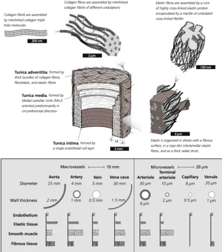
In principle, all vascular tissue in the body has the same structural layout. In short, three distinctive layers can be identified: the intima (tunica intima), the media (tunica media), and the adventitia (tunica adventitia or tunica externa), depicted in Figure 3.4.
The intima represents the lumen-facing innermost layer of the vessel, with its primary function related to cellular signalling and transport between blood stream and internal tissue [33]. The intima consists of a thin layer of endothelial cells, shown to have a significant influence on the initiation and development of vascular disease following its regulation of vascular tone and inflammatory response mechanisms [34]. However, the intima does not markedly influence the structural integrity of the vessel wall due to its limited thickness and lack of structural components [35].
The media is the middle layer of the vessel wall. In contrast to the intima, the media has a defined structural component, with the layer made up of a complex network of smooth muscle cells (SMCs), elastin and collagen fibres. In fact, sub-medial layers (so called sub-medial lamellar units (MLU) [36]) have been identified, with the orientation of collagen fibres in each MLU directly affecting the distribution of mechanical stress in the vascular wall [37, 38]. By such, the medial layer is identified as the mechanically most significant layer of the vessel wall [35], at least during the strain levels typically faced under normal physiological conditions.
The outermost layer of the vessel wall is the adventitia, mainly made up of bundles of collagen fibres in larger so called fibrils (themselves intertwined in a helical arrangement [39]). With its high collagen content, the adventitia acts as an outer protective mechanical layer, attaching the vessel to surrounding tissue and giving mechanical support at high intraluminal load, preventing vascular overstretch [35]. As mentioned, these three layers are in principle present throughout the vasculature, however differing in distribution and size throughout the body. Specifically, the cellular content and structural components within each layer of the
Figure 3.4: The structure of the vascular wall, showing its three main layers: tunica intima, tunica media, and tunica adventitia. Also, a diagram of tissue composition throughout the vasculature is given, illustrating differences in tissue structure. Modified and reproduced with permission [39, 40].
vessel wall vary distinctly based on the functional property of the given vasculature. As shown in Figure 3.4, the larger arteries and veins all have a relatively high degree of elastic tissue, together with reinforcing fibrous tissue and SMC content [40] in order to maintain the important distensible properties of the tissue, whilst still giving support for the forward-flowing blood. Notice also how the arterial side has a distinctly thicker vascular wall compared to the venous side, following the higher absolute blood pressures on the arterial side.
Conversely, in the more peripheral arterioles, capillaries, and venules, the elastic content of the vascular wall is significantly smaller, with the capillaries consisting almost exclusively of the thin intima endothelial layer [41]. This is all possible following the slow and continuous flow of blood in these peripheral parts of the vasculature.
3.1.3. Arterial-cardiac interaction
As described, the heart and the vasculature interact in a closed loop system, working in parallel to provide adequate blood flow throughout the pulmonary and systemic circulation. By so, cardiac alterations will result in vascular reactions, and vice versa – a concept often referred to as arterial-cardiac interaction or ventricular-vascular coupling [42, 43].
Two important concepts worth mentioning with regards to arterial-cardiac interaction are the pressure-volume diagram, and remodelling following vascular stiffening.
The pressure-volume diagram is a commonly deployed metric used to describe the relation between ventricular volume and pressure throughout the cardiac cycle, as depicted schematically in Figure 3.5. In principle, the pressure-volume loop connects the constitutive relation between pressure and volume at ventricular relaxation (the end-diastolic pressure-volume relation (EDPVR)) and the constitutive relation between pressure and volume at full ventricular contraction (the end-systolic pressure-volume relation (ESPVR)).
During diastole, the ventricles are filled and increase in volume from the end systolic volume (ESV) to the end diastolic volume (EDV), with the pressure-volume relation converging towards the EDPVR. At the point of EDV, the mitral valve closes, and the IVC is represented by the build-up in pressure without change in ventricular volume, as seen by the vertical rise in the pressure-volume diagram at EDV. Once the aortic valve opens, the curve loops back all the way to the ESPVR, reached just as the aortic valve closes. The cardiac cycle is then finalised and the pressure-volume diagram is closed once the IVR is completed. Importantly, this type of diagram depicts the relation between cardiac pressure and volume, and how increasing ventricular volumes will be resisted by an increasing work-load or counter-acting pressure. The diagrams can also help in the intuitive understanding of how myocardial constitutive behaviour affects cardiac efficiency, where myocardial stiffening (increasing slopes of EDPVR and ESPVR) will result in increased filling resistance. Similarly, the pressure-volume diagrams entail information on arterial influence, where the so called effective arterial elastance (Ea, connecting ESPVR and EDVR in Figure 3.5) will shift the pressure-volume relation as a function of peripheral resistance, preload, afterload, and heartrate, to name only a few [44-46].
Figure 3.5: Example of a normal pressure-volume loop (left), showing the relation between left ventricular pressure and volume which connects the end-systolic pressure volume relation (ESPVR) with the end-diastolic volume relation (EDPVR). Note the rapid changes in volume at the end systolic volume (ESV) and end diastolic volume (EDV), respectively, as well as the effective arterial elastance (Ea). The slope of Ea will also be related to several factors (right) such as total peripheral resistance (TPR), heart rate (HR), or preload. Modified and reproduced with permission [47].
3.1.4. Cardiovascular hemodynamics
As described in the previous few sections, the central role of the cardiovascular system is to transport blood throughout the entire body, maintaining systemic homeostasis. For this reason, disruptions in the natural flow of blood are often directly related to the onset of cardiovascular disease [48-51]. Similarly, it is by the unifying flow of blood that the heart and vasculature can interact and adapt to different physiological states [52, 53]. For this reason, a short review of the basics of cardiovascular hemodynamics is essential when reviewing cardiovascular function, and is here provided as a final and unifying component of cardiovascular physiology.
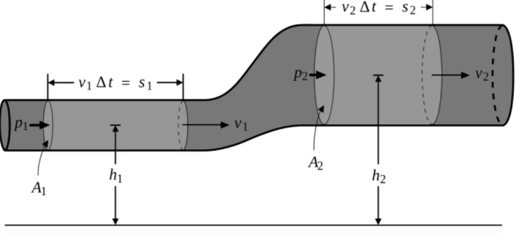
Figure 3.6: Schematic single pipe flow, used to describe Bernoulli’s principle. Modified with permission from Wikimedia commons.
a) Governing physical principles
From a fluid mechanical perspective, blood can be described in identical fashion to that of any given viscous fluid. By so, blood also follows the fundamental laws of fluid mechanics, described briefly in this section. Importantly, these theoretical descriptions provide a direct coupling between blood flow and blood pressure, and describe how these two interact at any given spatial or temporal point.
Even though strictly governed by the complete Navier-Stokes equations (explained in subsequent paragraphs), it is worth starting from a simpler description of flow. The Bernoulli equation is such a simplified formulation, stating that for an inviscid non-conductive fluid the sum of kinetic and gravitational potential energy is constant [54, 55]. If assessing a system such as the one depicted in Figure 3.6, this states that
1
2𝑣𝑣12+𝑝𝑝𝜌𝜌1+ 𝑔𝑔ℎ1=21𝑣𝑣22+𝑝𝑝𝜌𝜌2+ 𝑔𝑔ℎ2, (3.2)
with 𝑣𝑣 the velocity, 𝑝𝑝 the pressure, 𝜌𝜌 the density, 𝑔𝑔 the gravitational acceleration, and ℎ the height above a given reference plane. Index 1 and 2 refers to arbitrary positions along the vessel as shown in Figure 3.6. Assuming negligible gravitational effects (as commonly done in clinical practice [56, 57]), and re-ordering Equation 3.2, we reach a direct relation between velocity and pressure where
𝑝𝑝2− 𝑝𝑝1 =12𝜌𝜌(𝑣𝑣12− 𝑣𝑣22). (3.3)
In other words, a decrease in velocity will be reflected by an increase in pressure. Or: at any vascular narrowing where the cross-sectional decrease will lead to an increase in velocity (due to the conservation of mass), we will experience a decrease in pressure. Such changes in relative pressure is therefore a typical metric for assessing vascular coarctation narrowing [58, 59], valve stenosis [60, 61], etc. The Bernoulli equation is however only strictly valid for an inviscid non-conductive fluid. Additionally, the Bernoulli equation originates from a steady-state system, meaning that any transient inertial effects will not be taken into account. In the greater vessels of the vasculature, where we have a continuous pulsatile flow of blood, this is clearly not the case.
Expanding into an inviscid, non-conductive case however allowing for transient changes, Euler’s momentum equation states that
𝜕𝜕𝒗𝒗
𝜕𝜕𝜕𝜕+ 𝒗𝒗∙∇𝒗𝒗 = − 1
with 𝒗𝒗 denoting the 3D velocity vector. Reformulating Equation 3.4 into a 1D problem and re-organising terms, we get an expression for the infinitesimal pressure difference as
𝜕𝜕𝑝𝑝
𝜕𝜕𝜕𝜕= −𝜌𝜌 �𝜕𝜕𝑣𝑣𝜕𝜕𝜕𝜕+ 𝑣𝑣𝜕𝜕𝑣𝑣𝜕𝜕𝜕𝜕+ 𝑔𝑔𝜕𝜕ℎ𝜕𝜕𝜕𝜕�. (3.5) Again ℎ depicts the height above the reference plane in Figure 3.6, whereas 𝜕𝜕 and 𝑑𝑑𝜕𝜕 is a streamline and infinitesimal streamline step from 1 to 2, respectively. Integrating along 𝜕𝜕 and neglecting again all gravitational effects, we end up with the so called Unsteady Bernoulli equation [62], for which
𝑝𝑝2− 𝑝𝑝1= 𝜌𝜌 �12(𝑣𝑣12− 𝑣𝑣22) − � 𝜕𝜕𝑣𝑣𝜕𝜕𝜕𝜕 𝑠𝑠 𝑑𝑑𝜕𝜕�.
(3.6) As seen, Equation 3.6 is very similar to Equation 3.3, however now including the transient kinetic component of the velocity along 𝜕𝜕.
For a complete description of 3D blood flow we however resort to the Navier-Stokes equations, describing the conservation of mass and momentum for any incompressible fluid. Specifically, the Navier-Stokes equations state that for an isothermal, incompressible, Newtonian, viscous fluid the following holds
𝜌𝜌𝜕𝜕𝒗𝒗
𝜕𝜕𝜕𝜕+ 𝜌𝜌𝒗𝒗 ⋅ ∇𝒗𝒗 − 𝜇𝜇𝛻𝛻2𝒗𝒗 + 𝛻𝛻𝑝𝑝 = 0 (3.7)
∇ ⋅ 𝒗𝒗 = 0, (3.8)
with 𝜇𝜇 depicting the dynamic viscosity of the fluid. Importantly, the different terms in Equation 3.7 represents different fluid mechanical components of the flow. Specifically, the first and second term represent the kinetic and advective (or convective) inertia terms, describing the temporal and spatial flow resistance. The third term involves the viscous resistance, originating from the viscosity of the fluid, and lastly, the fourth term involves the spatial gradient of the pressure field. In addition to this, Equation 3.8 states the conservation of mass or divergence-free requirement, valid for any incompressible fluid.
Again, the fluid mechanical description gives us a direct connection between pressure and velocity, this time at any given 3D spatiotemporal point. However, non-linear terms and second order derivatives complicates accurate computation, and these full-form description are therefore rarely used in clinical practice [60, 61]. However, their incorporation may improve the accuracy of prediction [63-65], which will be a main topic of discussion in this thesis.
b) Turbulence
In the healthy human cardiovascular system, blood flows in a relatively stable way and transition into so called turbulent flow regimes are seldom encountered [66]. However following pathological disturbances, increasing vascular constriction and flow complexity may result in the development of these turbulent flow regimes [67-69].
Just as for laminar flows, the kinetic and advective inertia, viscous resistance, and pressure distribution can be described by the Navier-Stokes equations. However, for turbulent flows, stochastic and chaotic flow fluctuations will disturb the analytical assessment of the given flow field, introducing turbulence-driven variations in the evaluated terms.
A fully analytical description of turbulence is still not reached, in part because of the stochastic nature of turbulence [70, 71]. In laminar blood flow, the movement of blood is roughly assumed to repeat itself over consecutive cardiac cycles. On the contrary, even though turbulent regimes can be identified in given vascular structures, the specific flow behaviour at a given spatial positon will not be analytically repetitive. Instead, we will experience chaotic, stochastic fluctuations within these turbulent regimes. For that reason, we may treat turbulence in a statistical rather than analytical way.
Instead of assessing blood flow at a specific time point, we instead choose to observe the velocity field 𝒗𝒗 over 𝑛𝑛 number of cardiac cycles with period 𝑇𝑇. By so we can define a linear expected value operator 𝐸𝐸 (commonly used in probability theory [72]) collecting data over all cycles such that
𝐸𝐸[𝑣𝑣(𝜕𝜕)] =1
𝑛𝑛� 𝑣𝑣(𝜕𝜕 + 𝑘𝑘𝑇𝑇 ).
𝑛𝑛 𝑘𝑘=1
(3.9) Applying 𝐸𝐸 to our Navier-Stokes equations in 3.7-3.8, we get
𝜌𝜌𝜕𝜕𝐸𝐸[𝒗𝒗]𝜕𝜕𝜕𝜕 + 𝜌𝜌∇∙𝐸𝐸[𝒗𝒗𝒗𝒗] − 𝜇𝜇𝛻𝛻2𝐸𝐸[𝒗𝒗] + 𝛻𝛻𝐸𝐸[𝑝𝑝] = 0 (3.10)
∇∙𝐸𝐸[𝒗𝒗] = 0. (3.11)
Further, by setting 𝑽𝑽 = 𝐸𝐸[𝒗𝒗] and 𝑃𝑃 = 𝐸𝐸[𝑝𝑝] to be the mean of our observed velocity and pressure field, we can expand Equations 3.10 and 3.11 into
𝜌𝜌𝜕𝜕𝑽𝑽𝜕𝜕𝜕𝜕 + 𝜌𝜌∇∙𝐸𝐸[𝒗𝒗𝒗𝒗] − 𝜇𝜇𝛻𝛻2𝑽𝑽 + 𝛻𝛻𝑃𝑃 = 0 (3.12)
Lastly, it can be shown that 𝐸𝐸[𝒗𝒗𝒗𝒗] = 𝐸𝐸[𝒗𝒗]𝐸𝐸[𝒗𝒗] + Cov[𝒗𝒗, 𝒗𝒗] = 𝑽𝑽𝑽𝑽 + Cov[𝒗𝒗, 𝒗𝒗]. Here, Cov[𝒗𝒗, 𝒗𝒗] is the so called covariance matrix, describing the product of deviations in velocity from their expected mean value 𝑽𝑽. Using this in Equations 3.12-3.13 renders a final modification to the Navier-Stokes equations
𝜌𝜌𝜕𝜕𝑽𝑽
𝜕𝜕𝜕𝜕 + 𝜌𝜌∇∙(𝑽𝑽𝑽𝑽 ) + 𝜌𝜌∇∙Cov[𝒗𝒗, 𝒗𝒗] − 𝜇𝜇𝛻𝛻2𝑽𝑽 + 𝛻𝛻𝑃𝑃 = 0 (3.14)
∇∙𝑽𝑽 = 0, (3.15)
where specifically the term 𝜌𝜌∇∙Cov[𝒗𝒗, 𝒗𝒗] numerically handles flow deviations, typically arising from turbulent flows.
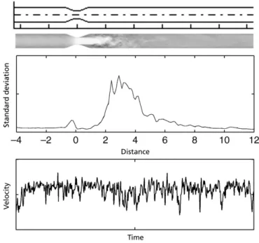
In summary, turbulence-driven stochastic flow fluctuations can thus be incorporated numerically into the analytical Navier-Stokes equations. From a practical point of view, this would be achieved by not only assessing the mean velocity and pressure field, but by including measures of covariance or deviation within an assessed flow field. As an example of how such incoherent velocity fluctuations might appear, Figure 3.7 depicts the flow in a stenotic flow phantom, where typical stochastic variations can be seen in velocity, together with an increase in flow deviations post-stenosis [73].
Figure 3.7: Illustration of incoherent flow fluctuations after a stenosis, presented for data from a stenotic flow phantoms: (top) phantom geometry and velocity field, with flow going from left to right, (middle) velocity standard deviations along the pipe length, and (bottom) velocity fluctuations over time post-stenosis. Modified and reproduced with permission [73].
c) Blood flow
Blood flow is a term typically used to refer to the motion of blood, or rather the velocity of blood in the cardiovascular system (a measure of distance travelled per unit time). With blood being continuously ejected from the heart, and with the anatomy of the vasculature changing throughout the body, blood flow will vary distinctly throughout the cardiovascular system. Inside the heart, peak velocities are typically encountered when blood is passed from atrium to ventricle during the early diastolic filling, with healthy peak intracardiac velocities of around 1.5 m/s [74]. The intracardiac movement of blood is itself a very complex process, where rotational spinning [18], vortex formation [75], and optimised redirection of blood towards ejection [76], seem to be common ventricular features.
Once ejected from the heart, slightly higher velocities can be seen across the pulmonary and aortic valves, however these quickly decrease as the blood travels towards more peripheral vessels. In fact, in the microcirculation significantly lower velocities of only a few mm/s are observed [77], before velocities are increased in the venous return.
The assessment of blood flow has become an instrumental part of routine clinical care. Blood flow over the intracardiac valves are part of echocardiography standard practice [6, 8] to evaluate valvular stenosis [61] or regurgitation [78], where guidelines are directly referring to velocity values in classifying disease stage [6, 61, 78]. Additionally, the development of full-field techniques such as 4D flow MRI, has opened up for expanded flow-based cardiovascular analysis, evaluating the 4D distribution of flow [10, 76, 79], vortices [19, 75], kinetic energy [80] and turbulence [81, 82], to mention only a few.
To quantify blood flow and describe cardiac function, a few standard metrics are commonly deployed. A few of these are:
i. End Diastolic Volume (EDV): Total amount of ventricular blood at the end of diastole. Typically around 140 mL in the healthy left ventricle [83]. ii. End Systolic Volume (ESV): Total amount of ventricular blood at the end
of systole. Typically around 50 mL in the healthy left ventricle [83]. iii. Ejection Fraction (EF): The ratio of ESV/EDV, representing the fraction
of blood being ejected from the ventricle. Typically around 55-70% [83]. iv. Stroke Volume (SV): The volume of blood being ejected in one heartbeat
(EDV – ESV). Typically around 95 mL [83].
v. Cardiac Output (CO): The volume of blood being ejected per unit time, generally given by SV times the patient heartrate. Typically around 4 L/min at rest [84].
All terms above by default refer to the left ventricle, but right ventricular values (given by an ‘RV’ prefix) can also be identically reported.
d) Blood pressure
Pressure is defined as force per unit area. For the cardiovascular system, this can be translated into that blood pressure is the pressure exerted by the blood onto the vascular wall.
A typical blood pressure curve recorded at two different points in the thoracic aorta is provided in Figure 3.8, showing the peak in systolic pressure, followed by a dropped diastolic pressure. The dicrotic notch typically appears following the closure of the aortic valve, hence representing the end of systole.
However, as described briefly in previous sections, blood pressure changes throughout the cardiovascular system partially follow the functional roles of the different parts of the vasculature. At the aortic outlet when the blood is ejected from the left ventricle, typical blood pressures values of 120/80 mmHg (systolic/diastolic) are reported [85]. However, following pathological changes, hypertensive or hypotensive states can significantly alter the range of both systolic and diastolic blood pressures seen in patients [86, 87].
With the ejected blood, a blood pressure pulse starts travelling through the cardiovascular system, changing its appearance and absolute values as showcased in Figure 3.8. The pressure wave gets distorted as it travels through the vasculature, and specifically, the systolic pressure peak increases and narrows in extension as we travel away from the heart. There are multiple reason to this change, but it originates in part from the narrowing of the arterioles, the changing velocity of the travelling pulse wave, the bifurcations and tortuous geometry of the vasculature, as well as from biomechanical properties of the vessel wall [40, 66, 88].
The increase in pressure pulse diminishes as the blood travels into the arterioles, where a distinct increase in vascular cross-section dampens both velocity and pressure. Again this is to enable nutrient exchange in the microcirculation [77]. As the pressure pulse changes throughout the vasculature, the assessment of relative pressure or pressure difference is common in clinical practice, reflecting this change in the travelling pressure pulse. Quite simply, the relative pressure denotes the difference in pressure between two given points. Figure 3.8 shows the absolute pressure recorded at the ascending and descending aorta, together with a subtraction of the two rendering the relative pressure between ascending and descending aorta.
With the pressure pulse varying with arterial properties, and similarly with pressure magnitude changing with changing cross-section (as described theoretically at the beginning of Section 3.1.4.), assessment of relative pressure can act as a valuable tool in assessing cardiovascular function. The metric is used as a recommended guideline metric for valvular stenosis and aortic coarctation [59, 61, 78], and have similarly shown value in assessing intracardiac pressure drops in patients with
hypertrophic cardiomyopathy [89, 90]. Similarly, the assessment of novel metrics such as so called hemodynamic forces [22, 91] have been related to evaluated pressure gradients, underlining the use of relative pressure.
A last note is that, confusingly, relative pressure nomenclature differs in literature, and different terms have interchangeably been used clinically. Typically we use the term pressure drop to denote the difference in pressure between two given positions. This is identical to the relative pressure. The pressure gradient is however the pressure drop over length between the same two positions.
Figure 3.8: Example of catheterised pressure measurements in the ascending (A) and descending (B) aorta, showing absolute pressure traces, as well as a derived relative pressure (A-B).