Journal of Chemical and Pharmaceutical Research, 2014, 6(3):679-688
Research Article
CODEN(USA) : JCPRC5
ISSN : 0975-7384
Research on the new load patterns for multi-roller stretch forming process
Zhang Wei-chuan
a*, Li Yong-feng
aand Li Ming-zhe
baKey Laboratory of Automobile Materials of Ministry of Education, College of Materials Science and Engineering,
Jilin University, Renmin Street, Changchun, China
bDieless Forming Technology Center, Jilin University, Renmin Street, Changchun, China
_____________________________________________________________________________________________
ABSTRACT
Multi-roller stretch forming process (MRSF) is a flexible manufacturing technique to form sheet panels into different curvature. Based on the geometrical relationship of 3D surface stretch forming by MRSF, an inscribed arc of the roller’s critical position has been established by adopting geometric analytical method. With the arc, the variation regulation of loading force on each roller is obtained using the principle that the stretch force on each roller stays the same in all places. Numerical simulations have been done for forming the 08Al spherical parts by MRSF with the equal force and variable force loading methods respectively. The results show that the flexibility, die fittingness, strain and stress distribution as well as the quality of variable force loading by MRSF are the best among these types, equal force loading method is a little worse than the former, however the traditional stretch forming process with rigid-clamps (RCSF) is not flexible and it is hard to make the blank and die jointed. In addition, the phenomenon of stress concentration is serious and the quality of the formed parts is the worst.
Key words: Flexible stretch forming, Loading pattern, Spherical part, Numerical simulation
_____________________________________________________________________________________________
INTRODUCTION
Traditional stretch forming process mainly depends on the movement of grippers and the lifting of the stretching machine table so as to make the blank jointed with the die surface to form the final part shape [1].
The blank appears strain concentration phenomenon made by the traditional stretch forming machine with integral clamps, especially when there is bidirectional large curvature, which may influence the quality of the formed part much [2, 3].
What is more, the load control method of traditional stretch forming is very complex, which needs repeatedly trial-stretching to confirm the optimal load track and relies on practical experience extremely, which can lead to unstable forming quality[4-6].
A Multi-roller flexible stretch forming experimental device has been developed by Jilin University. The device adopts force-loading pattern and has many advantages, such as simple structure, low cost, easy-controlled, etc. [7].
Fig.1 is the flexible roller stretch forming device, composed of flexible structure of roller device and flexible structure of clamp device which is made up of a number of clamps swinging around some certain axes [8].
Firstly, the blank is fixed by flexible clamps device. Secondly, the discrete rollers move downward vertically to the blank, until the blank joints with the die.
In this paper, the inscribed arc of the roller’s critical position when the blank joints with the die completely are established by adopting geometric analytical method. Combining with Newton’s dynamical theory with the arc, each roller’s optimal load model is calculated.
Through numerical simulation and experimental test, it shows that the quality of spherical shaped parts with variable load force is better than that with invariable force using flexible roller stretch forming which is also better than the traditional stretch forming with rigid clamps. In addition, the results prove the feasibility of variable load force and provide some reference to the development of multi-roller stretch forming device and the processoptimization [11-13].
Fig.1 Multi-roller stretch-forming device
2. GEOMETRIC MODEL OF MULTI-ROLLER STRETCH FORMING
In order to analyze the inscribed arc of the roller’s critical position theoretically, some corresponding assumptions can be made. In this paper, the thickness of blank can be neglected during calculating the parameters because the blank is very thin.Fig.2 is the schematic diagram of multi-roller flexible stretch forming principle(1/2 model).
Fig.3 is the geometric schematic diagram of a plane cut by the plane γ(x=0) .The device adopts floating clamps and the friction and inertial force of cylinder are neglected, so EQ can be regarded as a horizontal line.
When the rollers move downward to a certain position, the blank can joint with the die completely with the effect of the rollers. The ordinate of the tangency point E between the roller and blank is zE, accordingly, the descending
distance of rollers is H=z0-zE.z0 is the distance from the vertices to bottom of the die.
Fig.2 The principle schematic diagram Fig.3 The geometric schematic diagram of Multi-roller flexible stretch forming of Multi-roller flexible stretch forming
2.1. CRITICAL FITTINGNESS CONDITION OF SHEETMATERIAL
Without loss of generality, the forming surface of any die can be described as S and its equation is F(x,y,z)=0.The surface S is cut by plane γ(x=xi) which is vertical to x-axis, correspondingly, AM is the section line, which can be
The slope the A point is
i,
A
d x y dz
k
dy dy
, the slope of line AB tangent to curve AM is
,
,
i
AB A i m
m
d x y
k k K x l
y l
dy
, that is
,
( , ) i m B
AB i m
r
x l z
k K x l
l ( ) , so
,
,
B i m r i m
z
x l l K x l(1) According to the geometric relations,
2
1 i,m 1
BEr K x l
(2)
E B
z z BE (3)
Put the equation (1) and (2) into equation (3),
2
, , 1 , 1
E i m r i m i m
z
x l l K x l r K x l (4)
For spherical-shaped die with radius R0, the surface equation of die is
2 2 2 2
0
x y z R
For any given section plane curve γ(x=xi),it fits to the equation
2 2 2 2
0 i
z R (x y)
, taking partial derivative of the equation with respect to y , the slope of line AB can be described as
2 2 2
0
, m
AB i m
m m
l dz
k K x l
y l
dy R x l
(5)
Put equation (5) into (4):
2 2 2
0
2 2 2
0
2
2 2 2
0 1 1 m r E m m m m l l z x R x l
R x l
l r
R x l
(6)
From equation (6), we can know that in order to make the blank jointed with the die completely, tangent point E has to satisfy the inequality z(xi)≤zE(xi).
2.2 RELATIONSHIP BETWEEN STRETCHFORCE T AND LOADING FORCEF
In order to obtain the relationship between stretch force and loading force, the geometric relationship is simplified like Fig.4a which shows that the normal pressure NE and loading force F satisfy the equation approximately at the
position of point E:
NE= Fcosβ(7)
It can be seen from Fig.4b that the maximum stretching force Tmax given by the rollers to the blank and normal
pressure NE satisfy the relationship:
max max
2 sin cos sin
2 2
E
N T T
(8)
Combining equations (7) with (8), the following expression is obtained.
max
sin cos
F T
(9)
As the Fig.4c shows, Tmax can be divided into ox and oy directions of the component, they are the lengthwise
Here Tmax=Toy/cosα (10)
Put equation (10) into (9):
max
sin sin
cos cos cos oy oy
F T T kT
(11)
Where Toy is the maximum width direction stretch force, so Toy is a constant when the blank is given certain material,
thickness and elongation. So k is the coefficient of variation gradient of loading force F.
It can be got from the geometrical relationship shown in Fig.4c that:
2 22 0 cos 1 cos tan 1 sin m r m r m l l
l l x
l R
(12)
Combining equation (11) and (12),the following expression is obtained.
2 2 2 0 tan 1 ( ) m m r m r lk l l x
R l l
(13)
The slope of any point on the curve can be described as K(x) =dzE(x)/dx=-tanβ by making derivative to x of zE(x) in
equation (6), so the tanβ in equation (13) is given by the expression
2
2 2 3
0 2 2
0 3 2 2 2 2 0
tan
m m m r
E
m
l rx R l l l x x
R x dZ x
dx R x l
(14) (a)(b)(c)
Fig.4 Relationship between stretch force and loading force
3NUMERICAL CALCULATION
The software ABAQUS is chosen to simulate the multi-roller stretch forming process. The material of sheetmaterial
is 08AL and its basic size is 600×240×1mm.The radius R0 of spherical-shaped die is 300mm, the dimensions ofdie
are 300×250mm.The process parameters in the simulation are lm=150mm,lr=50mm,r=20mm,lf=110mm,lc=40mm.
Regarding symmetry center O of the blank as coordinate origin, the coordinates of each roller center in the line of x-axis are respectively: x1=0, x2=48, x3=96.
3.1. CRITICAL LINE OF DIEFITTINGNESS
amount of roller is Hi=z0-zE(xi),for spherical-shaped part, z0=R0.
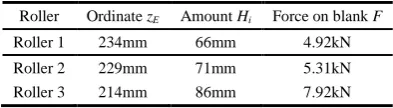
Table 1 is the maximum ordinate, minimum downward displacement amount of each roller and the force given by roller to the blank at the critical position.
A critical line (as shown in Fig.5) is obtained to evaluate whether the blank joints with the die completely according to numerical simulation.Fig.5 illustrates that when the ordinate zE of point E is below under the critical line, it means
[image:5.595.85.533.388.559.2]the blank joints well, otherwise not.
Table 1 The parameters of rollers when attaching die
Roller Ordinate zE Amount Hi Force on blank F
Roller 1 234mm 66mm 4.92kN
Roller 2 229mm 71mm 5.31kN
Roller 3 214mm 86mm 7.92kN
3.2 COEFFICIENT OF VARIATION GRADIENT
The changing relation curve between the coefficient k and the distance from roller center to point D is obtained from the formulas (10) and (11), at this time loading force F can ensure the lengthwise direction stretch force Toy loaded
by rollers are uniform as shown in Fig.6.The corresponding k are k1=0.50, k2≈0.5249, k3≈0.6055 when x1=0,x2=48,x3=96.
For the quarter model, the loading force of Roller1, Roller2 and Roller3 are F1/2, F2, F3and they accord with the
relationship: F1/2+F2+F3=Ftotal/4,in which, Ftotal is the total loading force of all rollers. Utilizing the equations F1=k1Toy,F2=k2Toy,F3=k3Toy,that is
Toy≈0.1811Ftotal (15)
Fig.5 The critical line of attaching-die Fig.6 The coefficient of variation gradient of different positions
4. SIMULATION ANALYSIS AND EXPERIMENT VALIDATION
According to simulation results, the maximum loading force of different stretch forming processes should be greater than or equal to the force on the blank by Roller3 when all rollers are in critical positions in order to ensure the blank joint with the die completely in different loading patterns. From Table 1, the force on the blank loaded by Roller3 is 7.92kN, rounding up the result, so Fmax=8.0kN.
In order to compare the precision of different loading patterns formed parts, the force of traditional stretch forming rigid clamps should be equal to the total loading force of all rollers of multi-roller stretch forming.
Table 2 The loading force of rollers in different loading patterns
Loading pattern Roller1/ kN Roller2/ kN Roller3/ kN Total force/ kN
Equal force 4.00 8.00 8.00 20.00
[image:5.595.171.440.712.750.2]Based on 1/4 model, Put Ftotal=80kN into equation (17), there are Toy≈14.49kN. The value of F1/2, F2and F3 are
3.62kN,7.60kN and 8.77kN by multiplying Toy with corresponding variation coefficient k1,k2 and k3,as shown in
Table 2.
4.1. THE RESULT OF NUMERICAL SIMULATION
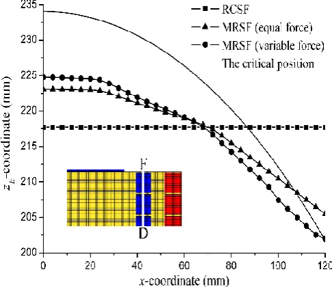
Fig.7 shows the relation curve between the ordinate zE of tangent point E with the distance from tangent point E to
point D for different loading patterns. From Fig.7, the attaching-die width of the blank reaches to 120mm by adopting multi-roller stretch forming with variable force loading, simultaneously, the blank joints to the die completely. However the attaching-die width are merely 108mm and 88mm respectively by using multi-roller stretch forming with equal farce loading and traditional stretch forming with rigid clamps.
[image:6.595.182.425.314.524.2]Therefore the flexibility, die fittingness, strain and stress distribution as well as the quality of variable force loading by MRSF are the best among these types, equal force loading method is a little worse than the former, however the traditional stretch forming process with rigid-clamps (RCSF) is not flexible and it is hard to make the blank and die jointed well. In addition, the phenomenon of stress concentration is serious and the quality of the formed parts is the worst. That is because the concentration force is dispersed to the discrete rollers that can arrange in a curve related to the end surface of the die, which will improve the flexibility and avoid the stress concentration phenomenon. Under the circumstance of multi-roller stretch forming with variable force loading, the loading force of each roller changes regularly according to the shape of the die’s end surface, making the stretch force to the blank by the roller more uniform and making die fittingness easier.
Fig.7 ZE varies with x in different loading patterns
(a) The traditional stretch forming process with rigid clamps
(c) Multi-roller stretch forming process (variable force loading) The plastic strain distribution in y direction
Fig.8 The plastic strain distribution in y direction of different stretch forming process.
In the blank width direction of spherical part extract the equivalent stress values and equivalent plastic strain values respectively of each node (on line CG and C1G1)where the stress distribute most non-uniform of different stretch
forming process and draw the curve as shown in Fig.9 and Fig.10.
The value difference between the maximum and the minimum equivalent stress of spherical part using multi-roller stretch forming with variable force loading is smaller than the one using multi-roller stretch forming with equal force loading and the one using traditional stretch forming with rigid clamps is the biggest and the stress distribution is most non-uniform, shown in Fig.9.Similarly, the Fig.10 shows the same regulation of equivalent plastic strain distribution.
(a) The equivalent stress curve on line CG (b) The equivalent stress curve on line C1G1
(a) The equivalent plastic strain curve on line CG (b) The equivalent plastic strain curve on line C1G1
Fig.10 The equivalent plastic strain curve in the blank width direction (on line CG and C1G1)
4.2 EXPERIMENT VALIDATION
Based on above numerical simulation and analysis, a stretch forming experiment on 08AL sheet blank (the area is 600×240mm2, the thickness is1mm) is designed, adopting the loading force shown in Table 2.Fig.11 shows the
formed spherical-shaped part by multi-roller stretch forming device. The formed spherical-shaped part has a good curvature in width direction, as shown in the Fig.11. This process is suitable for forming bidirectional large curvature surface part and the surface of effective formed area is smoother.
Fig.11 The spherical parts formed by MRSF prototype Fig.12 Error comparison between experimental results and numerical simulation results
Measure the spherical-shaped part after spring back by 3D scanner and extract the nodes data information of part surface. Comparing it with the nodes information of numerical simulation results, the error comparison diagram is drawn, as shown in Fig.12.The figure shows that the error between experimental results and numerical simulation results is small and almost distributes in -0.375 to 0.625.This means the numerical simulation results are almost in accord with the experimental ones.
CONCLUSION
MRSF is a new flexible stretch forming process. The loading force changing rule for the uniform stress of the blank is obtained through geometric analysis and Newton’s dynamical theory. Extensive numerical simulations of MRSF processes have been performed by dynamic explicit finite element methods, a series of numerical results are obtained, these results reveal the effects of different loading patterns on the sheet metal deformation.
The main points are concluded as follows:
1) The critical line of die fittingness is obtained with the geometric relationship of flexible roller stretch forming, it can be used to evaluate and judge the maximum die fittingness width, providing some guidance for simulation and experiment.
some guidance for the simulation of flexible roller stretch forming with variable force loading process and stretch parts.
3) Comparing traditional stretch forming process with flexible roller stretch forming process by means of numerical simulation on spherical-shaped part (R300mm), the results indicate that the flexibility, the die fittingness performance, the strain distribution and the stress distribution of flexible roller stretch forming process loaded by the variable force are the best, then, by the equal force. The traditional stretch forming process with rigid clamps is not flexible, and it is hard for the blank to joint with the die, in addition, it has serious stress-concentration phenomenon, the quality of the formed parts is relatively bad.
Acknowledgments
This work was supported by the National Science Foundation of China (50775098) and the “985 Project” of Jilin University of China
REFERENCES
[1] ZHANG Yan-min, ZHOU Xian-bin. Acta Aeronauticaet Astronautica Sinica, 2006, 27(6):1203-1208
[2] HOU Hong-liang, YU Xiao-fang, ZENG Yuan-song. Aeronautical Manufacturing Technology, 2009, (1): 34-39. [3] HAN Qi-gang, FU Wen-zhi, FENG Peng-xiao, et al. Aeronautical Manufacturing Technology, 2010, (24): 87-89. [4] ZHANG Hao-han, LI Ming-zhe, FU Wen-zhi. Journal of Jilin University: Engineering and Technology Edition, 2011,41(1):89-94
[5] ZHANG Yan-min, ZHOU Xian-bin. Journal of Beijing University of Aeronautics and Astronautics, 2007,33(7):826-829.
[6] HE De-hua, LI Dong-sheng, WU Zhi-min et al.. China Academic Journal Electronic Publishing
House,2010.137(04):137-140.
[7] ZHANG Hao-han. Research on process and numerical simulation of multi-roll flexible stretch forming [D]. Changchun: College of Materials Science and Engineering, Jilin University, 2011.
[8] ZHANG Hao-han, LI Ming-zhe, FU Wen-zhi et al. Journal of agricultural science and technology, 2012, 43(6):230-234
[9] LI Yong-feng, CONG Xiao-shuang, HE Xin-hua, et al. Journal of Plasticity Engineering, 2010,17(6):46-50 [10] MAO Meng-yun, HE Xin-hua, LI Yong-feng, et al. Forging & Stamping Technology,2010,35(5):100-104 [11] HUANG N E, ZHEN Shen, LONG S R, et al. Proc. R. Soc. Lond. A. 1998, 454: 903-995.