Procedia Engineering 53 ( 2013 ) 248 – 254
1877-7058 © 2013 The Authors. Published by Elsevier Ltd.
Selection and peer-review under responsibility of the Research Management & Innovation Centre, Universiti Malaysia Perlis doi: 10.1016/j.proeng.2013.02.033
Malaysian Technical Universities Conference on Engineering & Technology 2012, MUCET 2012
Part 1 - Electronic and Electrical Engineering
Design and Analysis of High Performance Reflectarray Resonant
Elements
Arslan Kiyani
a,* and M. Y. Ismail
a aWireless and Radio Science Centre (WARAS),University Tun Hussein Onn Malaysia, 86400 Parit Raja, Johor, Malaysia
Abstract
This paper reports on the performance comparison of different structures of reflectarray resonant elements operating in X-band frequency range. A thorough investigation has been carried out in terms of reflecting area, surface current density, reflection loss, 10% bandwidth, reflection phase and Figure of Merit (FoM). Predicted results based on Finite Integral Method (FIM) demonstrate that rectangular patch element with widest reflecting area of 105.46mm2 and surface current density of 162A/m is shown to offer minimum reflection loss and
static phase range of 0.23dB and 120° respectively, whereas triangular loop with a smallest reflecting area of 7.46mm2 and surface current
density of 3925A/m exhibits maximum reflection loss and static phase range of 3.90dB and 190°. Moreover it has been shown that FoM value increases with an increase in static phase range performance.
© 2013 The Authors. Published by Elsevier Ltd.
Selection and/or peer-review under responsibility of the Research Management & Innovation Centre, Universiti Malaysia Perlis.
Keywords: X-band; reflectarrays; resonant elements; surface current distribution; statci phase range; figure of merit.
1.Introduction
This Reflectarrays combine best features of parabolic reflectors and phased array antennas. A microstrip reflectarray consists of a flat array of printed radiating elements on a dielectric substrate which are illuminated by a feed horn antenna. This feeding method eliminates the complexity and losses of the feeding network used in planar arrays [1]. Reflectarray antennas with advantages of low profile, low mass, flat structure and high gain are considered for direct broadcast satellite (DBS) services and applications in microspacecraft missions [2], [3]. Despite these advantages the major shortcoming of reflectarrays is the narrow bandwidth, which is primarily limited by the patch elements, differential spatial phase delay [4], [5] and the phase errors related to the change in patch size [6]. Thick substrate has been proposed in the past as a method to broaden the bandwidth which would in turn reduce the slope of phase response. Unfortunately, the smaller attainable phase range in such cases has an adverse effect on gain and overall radiation efficiency [7]. Another major issue in the design of reflectarrays is the technique required for the phase compensation of adjacent elements. The individual elements of the reflectarray are designed to scatter the incident field with proper phase required to form a planar phase surface in front of the periodic array of the aperture [7]. Variety of resonant elements can be used for reflectarray unit cells such as identical
* Corresponding author. E-mail address: [email protected] © 2013 The Authors. Published by Elsevier Ltd.
patches of variable-length stubs [8], square patches of variable size [9], identical planar elements of variable rotation [10], cross-dipoles [11], [12] and ring elements [13], [14]. There are two main parameters that are important in the phase compensation process, the phase range and the phase characteristics gradient. Meanwhile the phase slope oversees the manufacturing tolerances and the operational bandwidth of the element [15].
The purpose of this research work is to analyze the reflection characteristics and phase range of various reflectarray resonant elements resonating in X-band frequency range. The variation of surface current density on the conducting surface of each resonant element at resonance has been investigated to examine the effects on the reflection loss and phase range performance.
2. Unit Cell Design Consideratrions
In order to investigate the scattering characteristics, the case of vertically polarized (Y-axis) TEM plane wave that is normally incident on an infinite periodic array of identical elements is considered. The incident wave propagates along Z-axis, whereas the E-field of the incident energy gets polarized in Y-axis and H-field of the incident energy is polarized in X-axis [16]. TEM consideration is employed by using commercially available CST computer model to provide a good approximation for the phase range and slope.
(a) (b) (c)
[image:2.544.141.403.252.376.2](d) (e) (f)
Fig. 1. Design and dimensions of reflectarray resonant elements (a) rectangular patch, (b) square patch, (c) triangular patch, (d) dipole, (e) square loop, (f) triangular loop
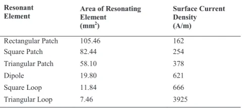
Table 1. Area And Surface Current Density Of Different Reflectarray Resonant Elements
Resonant
Element Area of ResonatingElement
(mm2)
Surface Current Density (A/m)
Rectangular Patch 105.46 162
Square Patch 82.44 254
Triangular Patch 58.10 378
Dipole 19.80 621
Square Loop 11.84 666
Triangular Loop 7.46 3925
In this section, different types of resonant elements are designed and analyzed by mounting on top of 1mm thick Rogers
r kness used
[image:2.544.154.394.430.537.2]3.Results and Discussion
3.1. Surface Current Density
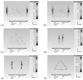
The incident TEM field generates electric current densities (J) on the conducting surfaces of the resonating elements. These fields are maximum at the resonant frequency. This is because at the resonant frequency the reflectivity of a reflectarray is at its maximum level and hence it offers higher losses [18]. The current distribution results generated from the commercially available computer model of CST are shown in Fig. 2. For all resonant elements it can be observed that maximum current is confined along the length of the patch at each opposite sides in vertical direction (Y-axis).
As depicted in Table I, rectangular patch with largest reflecting area of 105.46mm2 is shown to exhibit a minimum
surface current density of 162A/m. The surface current is increased up to 3925A/m when triangular loop with reflecting area of 7.41mm2 is made to operate at the same frequency. This high concentration of surface current distributions in triangular
loop is due to the fact that reduction in the geometrical dimensions enables the current to flow the long path along the curvature of the loop, hence offers the highest value of current density among all resonant elements. Thus, it can be concluded that reduction in the resonating area of the patch elements tends to increase the surface current density (J) and amount of current (I)
I
J ds
.
(1)Also (J) is related with the incident electric field (E) as represented by the following equation.
J
E
(2)Where
(a) (b)
(c) (d)
[image:3.544.126.412.336.610.2](e) (f)
3.2. Reflection Loss and 10% Bandwidth Performance
[image:4.544.173.376.148.292.2]Reflection loss is considered to be an important parameter in the analysis of loss performance of reflectarrays. Fig.3 shows the reflection loss curves of different resonating elements. It is illustrated in Fig. 3 that rectangular patch element is observed to offer the lowest reflection loss value of 0.23dB whereas triangular loop gives the highest reflection loss value of 3.90dB. This is significantly due to the fact that surface area of the triangular loop is very small as compared to rectangular patch element, which allows more current distribution to be concentrated in the central region of the length of the loop.
Fig. 3. Reflection loss curves of different resonant elements
Table 2. Reflection Loss and 10% Bandwidth
Resonant Element
Reflection Loss (dB)
10% Bandwidth (MHz)
Rectangular Patch 0.23 388
Square Patch 0.28 272
Triangular Patch 0.36 240
Dipole 0.76 124
Square Loop 1.49 84
Triangular Loop 3.90 76
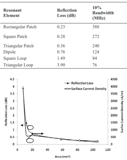
Fig. 4. Effect of area of reflectivity on the reflection loss and surface current density
[image:4.544.169.375.337.596.2]The results demonstrate that resonant elements with the highest surface current density are shown to give higher reflection loss whereas resonant elements with the lowest surface current density are observed to give broader bandwidth performance.
Fig. 4 shows the effect of reflective area of resonant elements on the reflection loss and surface current density. It can be seen that as the area reduces from 105.46mm2 to 7.46mm2, the reflection loss and surface current density increase from
0.23dB to 3.90dB and 162A/m to 3925A/m respectively. This is because the reflectarray resonant element with smallest area of resonance dissipates more energy into the substrate region which results in an increased surface current density and reflection loss value.
3.3. Reflection Phase and Figure of Merit (FoM)
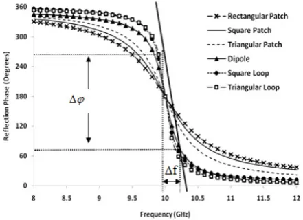
[image:5.544.154.375.265.425.2]Reflection phase is another important parameter that is used to analyze the reflectivity and bandwidth of reflectarrays. Moreover phase errors can also be observed using phase plots. The reflection phase curves for all the resonant elements are presented in Fig. 5. It can be observed form Fig. 5 that rectangular patch element acquire smoother phase characteristics gradient as compared to triangular loop, which is shown to exhibit the steepest phase characteristics gradient among all resonant elements. Since the overall phase variation is smaller than 360° therefore the maximum phase range can be obtained at the expense of steep slope, alternatively a smooth slope can be obtained at the expense of reduced phase range.
Fig. 5. Reflection phase curves of different resonant elements
The comparison of reflection phase performance can be indicated by Figure of Merit (FoM) and static phase range. FoM can be defined as the change in the reflection phase to the change in frequency and can be expressed as [20].
(
MHz)
FoM
f
(3)Static phase range and FoM values of various reflectarray resonant elements are depicted in Table III. It can be observed that rectangular patch element with minimum FoM value of 0.19°/MHz offers a minimum static phase range of 120° whereas triangular loop with maximum FoM value of 0.80°/MHz shows maximum static phase range of 190°. It can be seen that the static phase range performance is directly proportional to FoM.
Fig. 6 shows the relationship between bandwidth and static phase range performance. With an increase in surface current density of the resonant elements from 162 A/m to 3925A/m, the 10% bandwidth is shown to be decreased from 388MHz to 76MHz whereas static phase range is observed to increase from 120° to 190°. It can be seen that FoM is directly proportional to the static phase range and there prevails a tradeoff between bandwidth and static phase range performance.
Table 3. Static Phase Range and Figure of Merit (FoM)
Resonant Element
Static Phase Range (°)
Figure of Merit (FoM) (°/MHz)
Rectangular patch 120 0.19
Square patch 130 0.23
Triangular patch 140 0.27
Dipole 155 0.28
Square loop 170 0.72
Triangular loop 190 0.80
Fig. 6. Relationship between bandwidth and static phase range with variation in surface current density
4.Conclusion
Different unit cell elements have been analyzed for the performance optimization of reflect arrays. It has been shown that a reduction in reflecting area of the resonant elements modifies the electrical dimensions and surface current density which can significantly affect the reflection loss and reflection phase performance. Triangular loop is shown to offer greater static phase range as compared to other elements. It is shown that by employing triangular loop as reflect array resonant element the feasibility to enhance the static phase range can be realized. However the increase in the static phase range has to be traded-off with the bandwidth performance of reflect arrays.
Acknowledgment
The authors would like to thank the staff of Wireless and Radio Science Centre (WARAS) of University Tun Hussein Onn Malaysia (UTHM) for the technical support.
References
[1] J. Huang and J. Encinar, Reflectarray antennas, Wiley, Inter Science, 2007. [2]
[3] Report 42-120, 1995.
[4] -1491, 2003.
[5] search B, Vol. 3, pp.
173-187, 2008.
[6] ctions on Antennas and
Propagation, Vol. 46, No. 7, pp. 1134-1137, 1998. [7] D. M. Pozar,
Propagation, Vol. 45, No. 2, pp. 287-296, 1997.
[8] ing patches of variable size," IEEE Antennas and Propagation
Society International Symposium, Vol. 3, pp. 1820-1823, 1994.
[9] s and Propagation,
Vol. 43, No. 9, pp. 932-938, 1995.
[10] pagation Society
[11] cross elements for use 008.
[12] ernational
Symposium, Vol. 2, pp. 1008-1011, 1998.
[13]
-357, 2002.
[14]
-iWAT, pp. 163-166, 2008.
[15] ssive reflectarray antenna
-1222, 2009.
[16] F-C. E. Tsai and M. E. Bialk -element ku-band microstrip reflectarray of variable Size patches using an equivalent unit cell -2962, 2003.
[17] M. Hashim Dahri and M. Y. -188,
2011.
[18] D. M. Pozar, Microwave Engineering, John Willey & Sons, 2004.
[19] erformance of
x-and Optical Technology Letter, Vol. 53, No. 1, pp. 77-80, 2011.
[20] th and loss performance of reflectarray antennas based on material