A MULTI-BAND INTEGRATED ELECTROMAGNETIC FIELD DETECTION SYSTEM
ADEL YAHYA ISA ASHYAP
A project report submitted in partial
fulfillment of the requirements for the award of the Degree of Master of Electrical Engineering with Honours
Faculty of Electrical and Electronic Engineering Universiti Tun Hussein Onn Malaysia
ABSTRACT
CONTENTS
TITLE
DECLARATION DEDICATION
ACKNOWLEDGEMENT ABSTRACT
TABLE OF CONTENT LIST OF TABLES LIST OF FIGURES
LIST OF SYMBOLS AND ABBREVIATIONS LIST OF APPENDICES
i ii iii iv v vi
x xi xvii xviii
CHAPTER 1 INTRODUCTION
1.1 Project Background 1.2 Problem Statement 1.3 Objectives of the Project 1.4 Scopes of Project
1.5 Expected Results
CHAPTER 2 LITERATURE REVIEW 2.1 Overview
2.2 Theory of Electromagnetic 2.3 ICNIRP definitions and limits 2.4 Exposure Limits
2.5 Effects on General Health
2.6 Health and Safety Measure of Radiation 2.7 Frequency Chosen for the Project
2.8 Previous Research on Radiation Detector 2.8.1Electromagnetic Radiation Detector Badge 2.8.1.1 Advantage/Disadvantage of Detector Badge 2.8.2 Electromagnetic Field Detector
2.8.3 EMT Radiation Using Electric Field Probe 2.8.3.1 Advantage and Comparison of Probe 2.8.4 Electromagnetic Field Sensor
2.8.5 Electromagnetic Field Detector Bracelet 2.8.6 Sensitive Electromagnetic Radiation 2.8.7 EMF Detector
9 9 11 12 16 17 17 18 18 19 19 20 21 22 22 23 24
CHAPTER 3 METHODOLOGY 3.1 Introduction
3.2 Overall Functional Description 3.3 Design Architecture of the Detector 3.4 Project Sequence Overview
3.5 Phase 1: Gain Understanding on Background 3.6 Phase 2: Design a Small Size Antenna
3.6.1 Design Process Using Manual Calculation 3.6.1.1 Calculation for Dimension of the Rectangular 3.6.1.2 Calculation of the Width (W)
3.6.1.3 Calculation of the Effective Dielectric Constant 3.6.1.4 Calculation of the Effective Length
3.6.1.5 Calculation of the Length Extension 3.6.1.6 Calculation of Actual Length of Patch 3.6.1.7 Calculation of the Ground Plane Dimensions 3.6.1.8 Calculation of the Transmission Line Width 3.6.1.9 Summary for Dimension of the Rectangular 3.6.2 CST Microwave Studio
3.6.3 Receiver Stage
3.7 Phase 3: Design a Detector Circuit 3.7.1 RF Logarithmic Power Detector 3.8 Phase 4: Design and Develop PIC Circuit 3.8.1 Microcontroller
3.8.2 Calibration Stage
3.9 Phase 5: Develop a Graphical User Interface (GUI) 3.9.1Output Stage 36 36 36 37 38 39 40 42 42 47 47 48 51 51
CHAPTER 4 RESULTS AND ANALYSIS 4.1 Introduction
4.2 Receiver Stage
4.2.1 Simulation Results 4.2.2 Return Loss 4.2.3 Input Impedance
4.2.4 Voltage Standing Wave Ratio (VSWR) 4.2.5 Radiation Pattern
4.3 Measurement Using GTEM 4.3.1 Rectangular Patch Antenna 4.3.2 Isotropic Electric Field Probe 4.3.3 Detector and Amplifier Stage 4.4 Calibration Stage
4.5 Interfacing Stage (GUI)
CHAPTER 5 CONCLUSION AND RECOMMENDATION 5.1Conclusion
5.2Conclusion of the Project
5.3 Recommendations for Future Work
73 74 75
REFERENCES APPENDIX
LIST OF TABLES
1.1 Differences between Electric Field, Magnetic Field and Electromagnetic Field
3
2.1T : Reference Levels for Occupational Exposure to Time-Varying Electric and Magnetic Fields
15
2.2 Reference Levels for Current Induced in Any Limb 15 2.3 Reference Levels For General Public Exposure to
Time-Varying Electric and Magnetic Fields
16
3.1 Manually Calculated Parameter for Rectangular Patch Antenna
38
3.2 Manually and Modified Dimension of Rectangular Patch Antenna
40
LIST OF FIGURES
2.12.1
2.1 Reference Levels for Occupational Exposure to Time-Varying Electric and Magnetic Fields
12
2.1 Schematic Circuit Diagram of the Detector 18
2.3 Electromagnetic Field Detector 20
2.4 Schematic of the Electric Field Probe 21
2.5 Electromagnetic Field Sensor 22
2.6 The Electromagnetic Field (EMF) Detector Bracelet 23
2.7 Sensitive Electromagnetic Radiation 24
2.8 EMF Detector 24
3.1 Block Diagram of the Remote Monitoring System of EMF Detectors
27
3.2 Block Diagram of Three Remote EMF Detectors as Network Unit
27
3.3 Architecture of the Detector 28
3.4 General Methodology in the Implementation of the Project
3.5 Flow Chart of Designing Antenna. 33
3.6 Dimension of the Rectangular Patch Antenna. 34
3.7 Calculated Dimension of the Rectangular Patch Antenna
38
3.8 Workspace of CST Microwave Studio 39
3.9 Dimension of the Patch Antenna Model. 41
3.10 SMA to SMA Adaptor and SMA Connector 41
3.11 Patch Antenna Connected to the Detector and Amplifier Stage.
42
3.12 MAX4003- RF Logarithmic Power Detector 43
3.13 MAX4003 Pin Configuration. 44
3.14 Flow chart of Detector and Amplifier Stage. 45
3.15 Function of the Detector. 46
3.16 Detector and Amplifier Stage. 46
3.17 Designing of Detector and Amplifier Stage Using CST Software.
47
3.18 PIC16F876A 48
3.19 PIC16F876A Pin Configuration. 48
3.20 Flow Chart of the PIC. 49
3.21 PIC16F876A Pin Connections with Relevant Components using ISIS 7 Professional, (b) Layout
50
3.23 Flow chart of Labview. 52 4.1 The Simulated and Fabricated of Patch Antenna. 54 4.2 Simulated Return Loss of the Triple Band Antenna. 55 4.3 Measured Return Loss of the Triple Band Antenna. 55 4.4 Comparison of Simulated and Measured Return Loss. 56 4.5 Simulated Input Impedance of the Triple Band Antenna 57 4.6 Measured Input Impedance of the Triple Band Antenna 57 4.7 Simulated Voltage Standing Wave Ratios (VSWR). 58 4.8 Comparison between Simulated and Measured VSWR. 59 4.9a Simulated 3D form of Radiation Pattern of the
Rectangular Patch Antenna at 0.9GHz.
60
4.9b Simulated Polar form of Radiation Pattern of the Rectangular Patch Antenna at 0.9GHz.
60
4.10a Simulated 3D form of Radiation Pattern of the Rectangular Patch Antenna at 1.8GHz.
61
4.10b Simulated Polar form of Radiation Pattern of the Rectangular Patch Antenna at 1.8GHz.
61
4.11a Simulated 3D form of Radiation Pattern of the Rectangular Patch Antenna at 2.1GHz.
62
4.11b Simulated Polar form of Radiation Pattern of the Rectangular Patch Antenna at 2.1GHz.
62
4.12 Experiment Setup Using GTEM Cell to Measure Output Power at the Rectangular Patch Antenna
4.13 The Equipment Used for Measuring the Output Power from the Rectangular Patch Antenna
63
4.14 The Output Power at the Rectangular Patch Antenna versus the Power Transmitted From Rf Signal Generator
64
4.15 Experiment Setup Using GTEM Cell to Measure Electric Field Received
65
4.16 The Equipment Used for Measuring the Output from Electric Field Probe
65
4.17 The Electric Field Received at the Field Probe versus Power Transmitted From Rf Signal Generator
66
4.18 Experiment setup using GTEM cell to measure induced voltage
67
4.19 The Equipment Used for Measuring the Output from Combination of the Rectangular Patch Antenna Connected With Detector and an Amplifier Stage
67
4.20 The Induced DC Voltage versus Power Transmitted From Rf Signal Generator
68
4.21 The Induced DC Voltage versus Electric Field 69 4.22 a Light Display When PIC Input Value less Than 0.5V 70 4.22 b Light Display When PIC Input Value Between 0.5V
and 40V.
70
4.22 c Light Display When PIC Input Value Greater 40V. 71
LIST OF SYMBOLS AND ABBREVIATIONS AC ADC AMP AR CAD DC DFT DNA DXF EM EMF FI GDS GND - - - - - - - - - - - - - - Alternate Current Analog-to-Digital Converter Amplifier Anti-Reflecting Computer-Aided Design Direct Current
Discrete Fourier Transform Deoxyribonucleic Acid Drawing Exchange Format Electromagnetic
Electromagnetic Field Finite Integration
GTEM Hz IC IDE LED NC NRPB PIC RMS RCS RF RISC 3D - - - - - - - - - - - - -
Gigahertz Transverse Electromagnetic Hertz
Integrated Circuit
Integrated Development Environment Light Emitting Diode
Not Connected
National Radiological Protection Board Programmable Interface Controller Root Mean Square
Radar Cross Section Radio Frequency
LIST OF APPENDICES
APPENDIXA
Microcontroller coding 78
APPENDIXB
CHAPTER 1
INTRODUCTION
1.1 Project Background
Exposure to electromagnetic fields is not a new phenomenon. However, during the 20th century, environmental exposure to man-made electromagnetic fields has been steadily increasing as growing electricity demand, ever-advancing technologies and changes in social behaviour have created more and more artificial sources. Everyone is exposed to a complex mix of weak electric and magnetic fields, both at home and at work, from the generation and transmission of electricity, domestic appliances and industrial equipment, to telecommunications and broadcasting [1].
Electromagnetic fields (EMF) occur in nature and thus have always been present on earth. However, during the twentieth century, environmental exposure to man-made sources of EMF steadily increased due to electricity demand, ever-advancing wireless technologies and changes in work practices and social behavior [1].
Electric fields are created by differences in voltage, the higher the voltage, the stronger will be the resultant field. Magnetic fields are created when electric current flows, the greater the current, the stronger the magnetic field. An electric field will exist even when there is no current flowing. If current does flow, the strength of the magnetic field will vary with power consumption but the electric field strength will be constant [3].
Electric and magnetic fields (EMF) are areas of energy that surround any electrical device. Power lines, electrical wiring, computers, televisions, hair dryers, household appliances and everything else that uses electricity are sources of EMF. The magnetic field is not blocked by buildings so outdoor sources like power lines can add to the EMF inside your home. However, the field decreases rapidly with distance so that most homes are too far from high voltage lines to matter [4].
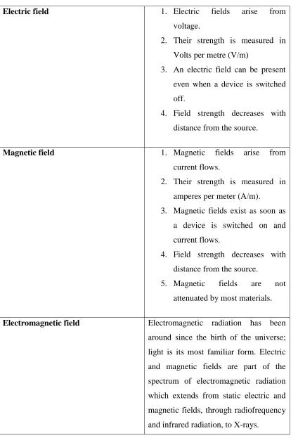
Table 1.1: Differences between Electric Field, Magnetic Field and Electromagnetic Field
Electric field 1. Electric fields arise from voltage.
2. Their strength is measured in Volts per metre (V/m)
3. An electric field can be present even when a device is switched off.
4. Field strength decreases with distance from the source.
Magnetic field 1. Magnetic fields arise from current flows.
2. Their strength is measured in amperes per meter (A/m). 3. Magnetic fields exist as soon as
a device is switched on and current flows.
4. Field strength decreases with distance from the source.
5. Magnetic fields are not attenuated by most materials.
Electromagnetic fields are present everywhere in our environment but are invisible to the human eye. Electric fields are produced by the local build-up of electric charges in the atmosphere associated with thunderstorms. The earth's magnetic field causes a compass needle to orient in a North-South direction and is used by birds and fish for navigation. Besides that the natural sources the electromagnetic spectrum also includes fields generated by human-made sources: X-rays are employed to diagnose a broken limb after a sport accident. The electricity that comes out of every power socket has associated low frequency electromagnetic fields. And various kinds of higher frequency radio waves are used to transmit information – whether via TV antennas, radio stations or mobile phone base stations [3].
Exposure limit has been specified by the World Health Organization (WHO) and the International Commission on Non-Ionizing Radiation Protection (ICNIRP). Electric and magnetic fields (EMF) are invisible lines associated with the use of electric power. The time-varying electromagnetic fields produced by electrical appliances are an example of extremely low frequency (ELF) fields. ELF fields generally have frequencies up to 300 Hz. Other technologies produce intermediate frequency (IF) fields with frequencies from 300 Hz to 10 MHz and radiofrequency (RF) fields with frequencies of 10 MHz to 300 GHz. The effects of electromagnetic fields on the human body depend not only on their field level but on their frequency and energy. Our electricity power supply and all appliances using electricity are the main sources of ELF fields; computer screens, anti-theft devices and security systems are the main sources of IF fields; and radio, television, radar and cellular telephone antennas, and microwave ovens are the main sources of RF fields. These fields induce currents within the human body, which if sufficient can produce a range of effects such as heating and electrical shock, depending on their amplitude and frequency range. (However, to produce such effects, the fields outside the body would have to be very strong, far stronger than present in normal environments) [5].
circulating currents within the human body. The strength of these currents depends on the intensity of the outside magnetic field. If sufficiently large, these currents could cause stimulation of nerves and muscles or affect other biological processes [6].
High-frequency fields heat the human body. The degree of absorption of electromagnetic waves is a function of the frequency and intensity of the field and the type of tissue. The organs with the least blood flow are most endangered, e.g. the eyes. In contrast, the heart and brain are better at handling heat due to their better blood flow. Potential health effects of man-made EMF have been a topic of scientific interest since the late 1800s,and have received particular attention during the last 30 years.EMF can be broadly divided into static and low-frequency electric and magnetic fields, where the common sources include power lines, household electrical appliances and computers, and high frequency or radiofrequency fields, for which the main sources are radar, radio and television broadcast facilities, mobile telephones and their base stations, induction heaters and anti-theft devices [6].
1.2 Problem Statement
Humans actually live in an invisible sea of electromagnetic field energy. Subtle energies constantly swirl in and around their bodies, whether or not they were aware of them. The effects of external exposure to EMF on the human body and its cells depend mainly on the EMF frequency and magnitude. At low frequencies, EMF passes through the body while at radio frequencies the fields are partially absorbed and penetrate only a short depth into the tissue. Experimental and epidemiological data from the IF (Intermediate frequency fields) range are very sparse. Therefore, assessment of acute health risks in the IF range is currently based on known hazards at lower frequencies and at higher frequencies. Proper evaluation and assessment of possible health effects from long-term exposure to IF fields are important because human exposure to such fields is increasing due to new and emerging technologies. According to the World Health Organization, there are certain forms of electromagnetic radiation that are unquestionably hazardous to human health. Microwaves cook food by bombarding them with electromagnetic waves. X-rays are a form of electromagnetic radiation that can cause cancer in fairly short order. And gamma rays are electromagnetic waves that can inflict fatal radiation poisoning in seconds. Some individuals report "hypersensitivity" to electric or magnetic fields. They ask whether aches and pains, headaches, depression, lethargy, sleeping disorders, and even convulsions and epileptic seizures could be associated with electromagnetic field exposure. According to New South Wales Government Australia, 1999 “It has not been established that electric fields or magnetic fields of power frequency are harmful to human health, but since there is some evidence that they may do harm, a policy of prudent avoidance is recommended.
1.3 Objectives of the Project
The objectives for this project are:
i. To design a microstrip patch antenna which operates at 0.9GHz, 1.8GHz and 2.1GHz and act as receiver stage of the system.
ii. To design a detector and amplifier circuits which consist of RF logarithmic power detector that performs the task of conversion from AC to DC conversion and a microcontroller use to compares the voltage received from the detector with predetermined values.
iii. To develop a network of three detectors controlled by central unit.
iv. To implement an efficient Graphical User Interface (GUI) for the EMF network.
1.4 Scopes of the Project
This project is divided into six major phases:
i. First involves designing a microstrip patch that operates at 0.9GHz, 1.8GHz and 2.1GHz.
ii. Second the simulation process will occur to simulate the parameters of the antenna such as radiation pattern and return loss by using CST microwave studio followed by the fabrication using FR4 dielectric substrate and measurement for the return loss using Network Analyzer.
iii. Third involves designing and fabrication a detector and amplifier circuits which consist of RF logarithmic power detector that performs the task of conversion from AC to DC.
iv. Fourth involves designing and programmed a microcontroller using PIC16F876A.
v. Fifth involves calibrated using GTEM Cell to find the relationship between electric field received and induced DC voltage.
1.5 Expected Results
i. The device function properly and precisely to detect the EMF radition .
ii. Able to identify whether the exposed electric field at the particular location exceeds the permissible level.
CHAPTER 2
LITERATURE REVIEW
2.1 Overview
This chapter reviews a brief introduction of electromagnetic radiation, and a brief of previous studies will be conducted on this chapter.
2.2 Theory of Electromagnetic
Electromagnetic field is a physical field produced by electrically charged objects. It affects the behaviour of charged objects in the vicinity of the field. The electromagnetic field extends indefinitely throughout space and describes the electromagnetic interaction. It is one of the four fundamental forces of nature (the others are gravitation, the weak interaction, and the strong interaction) [11].
The field can be viewed as the combination of an electric field and a magnetic field. The electric field is produced by stationary charges, and the magnetic field by moving charges (currents), these two are often described as the sources of the field [11]. The way in which charges and currents interact with the electromagnetic field is described by Maxwell's equations and the Lorentz force law.
ELF magnetic fields was about ten times stronger than that resulting from all natural planetary and cosmic events, doubling the ELF fields monitored less than a decade earlier. A spectrum analysis done in Ottawa in 1982 showed radiation from 60 hertz power lines, hydro stations, 10 hertz Soviet radar emissions, and signals from the Soviet Union, Japan, China, Europe and Africa [12].These all contribute to the changes we see today. This permeates our homes, work places, industries and our outdoors and it increases every year as we pollute more and more electromagnetically, and creates a tremendous stress to all living systems. Since all living organisms on earth are exposed to electromagnetic radiation, it is urgent to establish standards of acceptable exposure levels for various frequencies of electromagnetic radiation. Cancer, birth defects, decreased immunity to disease even new sicknesses have been linked to extended exposure to electromagnetic fields of specific frequencies and intensities. Perhaps this may account for the much higher susceptibility to death from AIDS in regions of highest electromagnetic pollution.
2.3 ICNIRP definitions and limits
The main objective of ICNIRP is to establish guidelines for limiting EMF exposure that will provide protection against known adverse health effects. Two classes of guidance are presented in frequency between 1 Hz to 10 GHz [14]:
i. Basic restrictions: Restrictions on exposure to time-varying electric, magnetic, and electromagnetic fields that is based directly on established health effects. Depending upon the frequency of the field, the physical quantities used to specify these restrictions are current density (J), specific energy absorption rate (SAR), power density (S) and internal electric field strength (Ei) which is the electric field
affects the nerve cells and other electrically sensitive cells [14].
2.4 Exposure Limits
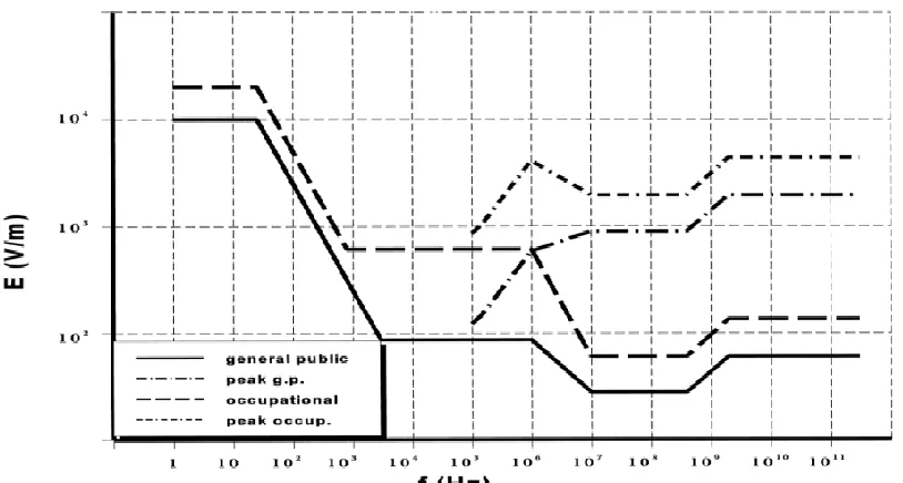
[image:27.612.125.532.286.504.2]The ICNIRP standard has exposure limits for electric fields and magnetic fields that are whole-body and time averaged. Exposure limits are given from DC to 300 GHz. Exposure limits for the magnetic (H) field are relaxed below 100 MHz since the exposure limits at lower frequencies are based more on electro stimulation than body heating and both induced and contact currents are related to the strength of the electric field. There are also limits for induced currents and contact currents. Figure 2.1 depicts the exposure limits that have been set by the International Council on Non-Ionizing Radiation Protection (ICNIRP) [15].
Figure 2.1: Reference Levels for Occupational Exposure to Time-Varying Electric and Magnetic Fields (unperturbed RMS values)
laboratory and epidemiological studies, basic exposure criteria, and reference levels for practical hazard assessment are discussed, and the guidelines presented apply to occupational and public exposure. Guidelines on high-frequency and 50/60 Hz electromagnetic fields were issued by IRPA/INIRC in 1988 and 1990, respectively, but are superseded by the present guidelines which cover the entire frequency range of time-varying EMF (up to 300 GHz). Static magnetic fields are covered in the ICNIRP guidelines issued in 1994 (ICNIRP 1994). In establishing exposure limits, the Commission recognizes the need to reconcile a number of differing expert opinions. The validity of scientific reports has to be considered, and extrapolations from animal experiments to effects on humans have to be made [14].
The restrictions in these guidelines were based on scientific data alone; currently available knowledge, however, indicates that these restrictions provide an adequate level of protection from exposure to time-varying EMF. Two classes of guidance are presented. The basic restrictions: Restrictions on exposure to time-varying electric, magnetic, and electromagnetic fields that are based directly on established health effects are termed "basic restrictions". Depending upon the frequency of the field, the physical quantities used to specify these restrictions are current density (J), specific energy absorption rate (SAR), and power density (S).Only power density in air, outside the body, can be readily measured in exposed individuals.
be exceeded. However, whenever a reference level is exceeded, it is necessary to test compliance with the relevant basic restriction and to determine whether additional protective measures are necessary [14].
Table 2.1: Reference Levels for Occupational Exposure to Time-Varying Electric and Magnetic Fields (Unperturbed RMS Values) [14].
Frequency Range (F)
Electric Field (E)
(V/m)
Magnetic Field (H)
(A/m)
Power Density (S)
(E,H Fields) (mW/cm2 )
<1 Hz - 163 x 10³ -
1 – 8 Hz 20,000 163 x 10³/f² -
8 - 25 Hz 20,000 2.0 x 10⁴/f -
0.025 – 0.82 kHz 500/f 20/f -
0.82 - 65 kHz 610 24.4 100; 22,445
0.065 - 1 MHz 610 1.6/f 100; 100/f²
1 – 10 610/f 1.6/f 100/f²
10 - 400 MHz 61 0.16 1.0
400 – 2,000 MHz 3f½ 0.008f½ f/400
2 – 300 GHz 137 0.36 5.0
The frequency dependence of the reference field levels is consistent with data on both biological effects and coupling of the field.
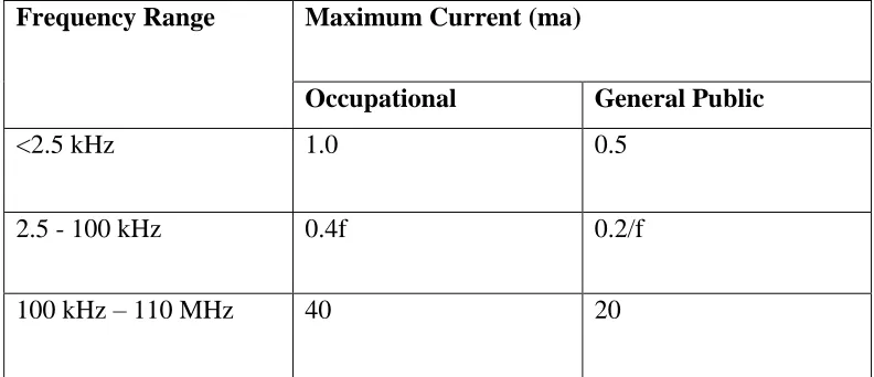
Table 2.2: Reference Levels for Current Induced in Any Limb [14].
Frequency Range Maximum Current (ma)
Occupational General Public
<2.5 kHz 1.0 0.5
2.5 - 100 kHz 0.4f 0.2/f
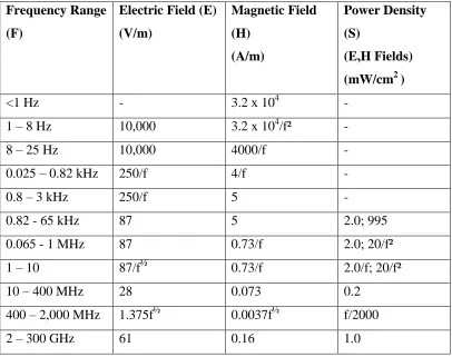
[image:30.612.129.525.539.710.2]Table 2.3: Reference Levels For General Public Exposure to Time-Varying Electric and Magnetic Fields (Unperturbed RMS Values) [14].
Frequency Range (F)
Electric Field (E) (V/m)
Magnetic Field (H)
(A/m)
Power Density (S)
(E,H Fields) (mW/cm2 )
<1 Hz - 3.2 x 10⁴ -
1 – 8 Hz 10,000 3.2 x 10⁴/f² -
8 – 25 Hz 10,000 4000/f -
0.025 – 0.82 kHz 250/f 4/f -
0.8 – 3 kHz 250/f 5 -
0.82 - 65 kHz 87 5 2.0; 995
0.065 - 1 MHz 87 0.73/f 2.0; 20/f²
1 – 10 87/f½ 0.73/f 2.0/f; 20/f²
10 – 400 MHz 28 0.073 0.2
400 – 2,000 MHz 1.375f½ 0.0037f½ f/2000
2 – 300 GHz 61 0.16 1.0
2.5 Effects on General Health
2.6 Health and Safety Measure for Electromagnetic Radiation
The National Radiological Protection Board (NRPB) has published guidance on exposure to non-ionizing radiation. This document recommends investigation levels which set the power density above which people should not normally be exposed. In the relevant frequency range this is 100 watts per square meter (100 W/m2), this is the same as 10 milliwatts per square centimeter (10mW/cm2). As such, it is not safe for humans to be exposed by electromagnetic field which has a power density above10mW/cm2. This value is used as a guideline when comparing with the detected field. When the particular detected field‟s power density is higher or near to10mW/ cm2, the alert device is triggered [14].
2.7 Frequency Chosen for the Project
2.8 Previous Research on Electromagnetic Radiation Detector
2.8.1 Electromagnetic Radiation Detector Badge
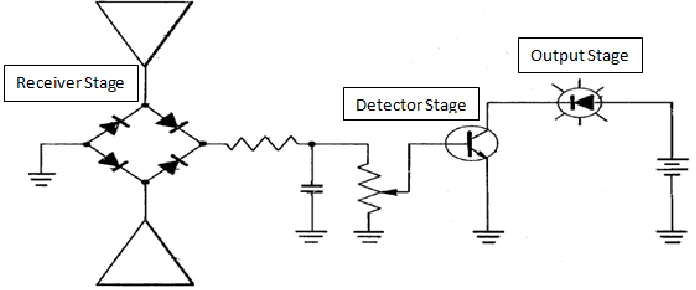
An electromagnetic radiation detector badge has been proposed by Bernard Lanoe and Elisabeth de Metz. An electromagnetic radiation detector were developed and attached inside a batch similar design. The radiation receiver used to detect the electromagnetic field is a two dipole antenna and the voltage detector used is a NPN transistor [17]. The schematic diagram of the radiation detector is shown in Figure 2.2.
[image:33.612.153.501.467.612.2]A full-wave bridge rectifier is used to rectify the AC input signal from the antenna to a DC output which later will filter by a resistor and capacitor before the signal is connected through a potentiometer to the base of an NPN transistor connected in a grounded or common emitter configuration. Transistor acts as an electronic threshold amplifier switch and the switching threshold is defined by the position of the tap of potentiometer. The collector of transistor is connected to the input terminal of an electroluminescent diode. In operation, when the level of radiation received by antenna has been such that the resultant DC voltage at the base triggers transistor, diode is energized by lighted up and emitted a red light.
2.8.1.1 Advantage/Disadvantage of the Research with this Project
Even though the proposed design above can be used to detect electromagnetic field, but there are several disadvantage on it. First, the two dipole antenna used is bulky and not suitable to be used in a hand held device or a badge as proposed by the inventor. Microstrip patch antenna is more suitable in fulling such task due to its simplicity, less expensive to manufacture, more compatible and require less space. Second, the rectifying circuit used is too simple where it is not possible to rectify and produce a smooth and precise DC voltage signal. The resultant DC voltage signal produced by the above mentioned circuit could be inaccurate. Third, the radiation detector could not indentify whether the detected electromagnetic field is in safe exposure level or not. Hence, the proposed design does not stand for its name as electromagnetic radiation detector but more to just an ordinary electromagnetic field detector.
2.8.2 Electromagnetic Field Detector
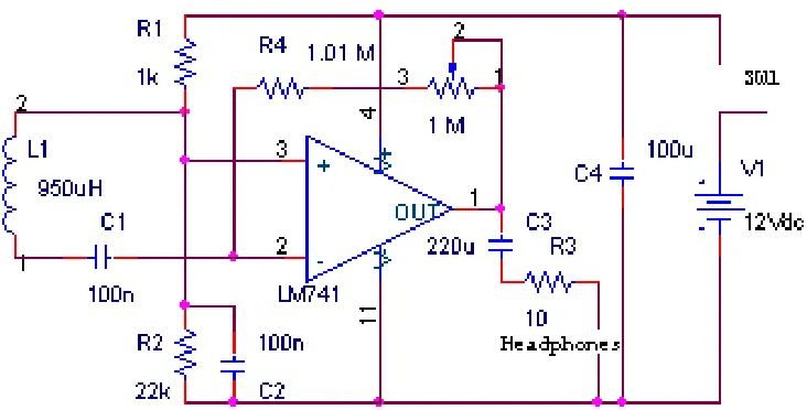
The field detector was designed [18] in four basic parts: a probe, an amplifier, a power
supply, and headphones. The schematic of the designed circuit is shown in Figure 2.3. A
radial type 950uH inductor is used as the device to sense the electromagnetic fields
produced. The signal is then sent through a differentiator consisting of an operational
amplifier with a negative feedback loop. A potentiometer is placed within the loop to
control the gain of the amplifier stage. A pair of headphones is used to hear the
amplified signal, which sounds like a 60Hz buzz. The operational amplifier is powered
by a 12V DC power supply connected to a SPST switch. The entire circuit is enclosed in
a black plastic box with the switch, potentiometer, headphone jack and probe wire
external to the box. The probe itself uses an empty pen tube to hold the radial inductor.
There were several capacitors used for AC and DC coupling purposes. Capacitor C1 AC
couples the input source (the probe signal) into the amplifier stage. C2 acts as a
grounding capacitor, whereas C3 again is used to AC couple the output signal to the
headphones. C4 is used to DC couple the supply voltage to the amplifier supply pins.
The disadvantage of this system doesn‟t have the ability to indentify whether the detected electromagnetic field is in safe exposure level or not. The system may doesn‟t have the ability to produce smooth DC due to the simplest of the circuit and the effect of
active component at higher frequency.
Figure 2.3: Electromagnetic Field Detector
2.8.3 Electromagnetic Radiation Detector Using Electric Field Probe
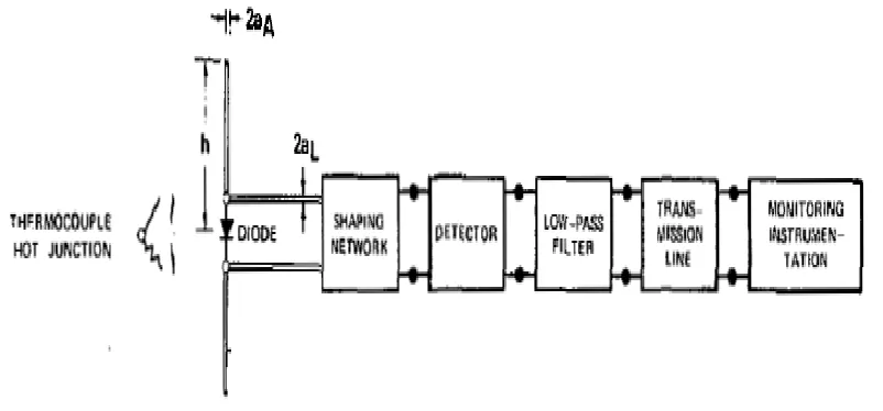
An electromagnetic radiation detector using electric field probe has been proposed by Howard I. Bassen and Glenn S. Smith. They proposed an electromagnetic radiation detector using an electric field probe consisting of a dipole antenna, Radio Frequency (RF) detector, and non-perturbing transmission line and readout device [19]. The schematic of the probe is shown in Figure 2.4.
[image:35.612.145.511.170.356.2]in the probe was an unbiased point contact or schottky barriediode operating in the square-law region, or a thermocouple junction.
Figure 2.4: Schematic of the Electric Field Probe
2.8.3.1 Advantage/Disadvantage of the Research with this Project
2.8.4 Electromagnetic Field Sensor
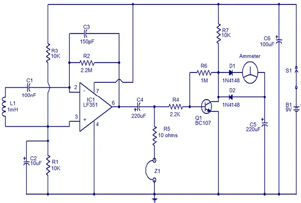
[image:37.612.173.479.291.497.2]This is the circuit diagram of a very sensitive electromagnetic field sensor which can sense electromagnetic field from 40Hz to 140Hz. The low noise opamp LF351 and associated components forms the pick-up section. 1uH coil L1 is used for sensing the field and the IC1 performs the necessary amplification. If the picked electromagnetic field is in the audio frequency range, it can be heard through the head phone Z1.There is also a meter arrangement for accurate measuring of the signal strength. Transistor Q1 performs additional amplification on the picked signal in order to drive the meter as shown in Figure 2.5.
Figure 2.5: Electromagnetic Field Sensor
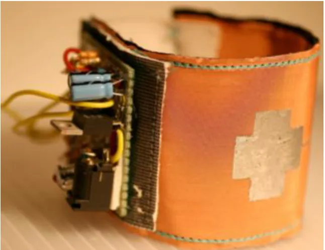
2.8.5 Electromagnetic Field Detector Bracelet
bracelet that responds to the non-perceived EMF that surrounds us (see Figure 2.6) that lies beyond human perception.
Figure 2.6: The Electromagnetic Field (EMF) Detector Bracelet
2.8.6 Sensitive Electromagnetic Radiation
Figure 2.7: Sensitive Electromagnetic Radiation
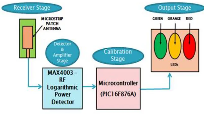
2.8.7 EMF Detector
This system was design to detect the radiation at 900MHz. but the system was not design successfully and does not work properly [21]. Below is the block diagram for the system as shown in Figure 2.8.
[image:39.612.163.491.449.633.2]REFERENCES
[1] S. Lagorio, “[Electromagnetic fields and public health in Italy].,” Epidemiologia e prevenzione, vol. 25, no. 3, pp. 127–9.
[2] C. Electric and M. F. Program, “What are electric and magnetic fields and why are people concerned about them ”.
[3] E. Of, T. H. E. Exposure, T. O. Electromagnetic, and S. Workplace, “Effects of the exposure to electromagnetic fields: from science to public health and safer workplace,” no. April, 2008.
[4] “Electric and Magnetic Fields ( EMF ): Health Concerns How Are Electromagnetic Fields What Are Typical EMF Levels Within A Home ? Is EMF Exposure Harmful ?”
[5] H. Ghz, “Implementation report on the Council Recommendation limiting the public exposure to electromagnetic fields,” pp. 1–53, 1995.
[6] WHO 2007b: World Health Organization, What are electromagnetic fields. (Accessed: 2013-3-25)
http://www.who.int/peh-emf/about/Whatis EMF/en/index1.html1 [7] [access: March 11, 2013]
http://www.narda-sts.us/fundamentals_effects.php
[8] D. S. Place and S. Lanka, “A publication of the Epidemiology Unit Ministry of Healthcare and Nutrition,” no. October, pp. 1–4, 2010.
[10] M. Repacholi and P. Ravazzani, “Electromagnetic Hypersensitivity,” 2004.
[11] Clayton R. Paul (1987). “Introduction to Electromagnetic Fields.” 2nd .ed. Mc Graw Hill.
[12] “Health and Environment” [access: April 2013]
url: http://www.gsmworld.com/health/links/conclusions.shtml [13] “Electromagnetic Fields” [access: March 29 2013]
url:http://www.who.int/peh-emf/about/WhatisEMF/en/index1.html
[14] ICNIRP 1998a: International Commission on non-ionizing Radiation Protection, Guidelines for limiting exposure to time-varying electric, magnetic, and electromagnetic fields (up to 300 GHz), Health Physics 74 (4), page 494-522,
1998.
[15] [access: April 28, 2013]
url: http://www.powerwatch.org.uk/science/intguidance.asp
[16] ICNIRP 2003: International Commission on non-ionizing Radiation Protection, Guidelines on determining compliance of exposure to pulses and complex non- sinusoidal waveforms below 100 kHz with ICNIRP guidelines, Health Physics 84
(3), page 383-387, 2003.
[17] Bernard Lanoe and Elisabeth de Metz, Electromagnetic Radiation Detector, United States Patent, Dec 1975.
[18] A. Lewis, K. Penney, J. Patterson, and K. Penney, “Electromagnetic Field Detector,” no. 303, pp. 3–5.
[19] H. I. Bassen and G. S. Smith, Electric Field Probes-A Review, IEEE Transactions on Antennas and Propagation, vol. 31, no. 5, page 710, 1983.
[20] C. Vaucelle, H. Ishii, and J. A. Paradiso, “Electromagnetic Field Detector Bracelet.”