2016 International Conference on Computational Modeling, Simulation and Applied Mathematics (CMSAM 2016) ISBN: 978-1-60595-385-4
Numerical Simulation on the Ignition Characteristics of the Inner Hole
Surface of Perforated Propellant Grains
Xiao XU and Dong-yao LIU
*Energy and Power Engineering College,Nanjing University of Science and Technology, Nanjing, Jiangsu, China 210094
*Corresponding author
Keywords: Propellant, Gas flow, Heat transfer, Ignition characteristics.
Abstract. The flow and heat transfer process of ignition flame in the inner hole of perforated propellant grains as well as the ignition characteristics of its inner surface are studied in this paper. An unsteady one-dimensional flow model of ignition flame in the micro-perforated inner hole was proposed according to the physical model of flow. Meanwhile, by the considering the convection and radiation between ignition flame and the inner surface of propellant, a transient one-dimensional model of heat transfer was derived. The flow process of ignition flame in the hole as well as heat transfer process between flame and inner surface is simulated by appropriate scheme. The variation and distribution of inner surface temperature as well as the temperature, pressure and velocity of ignition flame are illustrated and analyzed. The numerical results indicated that the ignition of the inner surface of propellant grains does not occur at the same time, the non-simultaneous ignition of the propellant surface will change the combustion properties of propellant.
Introduction
The burning surface areas of propellant grains decide the producing brisance of combustion gases, which dominate the variation of chamber pressure during the interior ballistic process[1,2] of propulsion. In order to manipulate the combustion gases production, and then to optimize the interior ballistic performances, the propellant grains are usually designed and manufactured into sophisticated structure with inner holes, such as tubular propellants or multi-perforated propellants. The progressive burning properties [3] of propellant grains with inner holes can compensate the pressure drop for the movement of projectile in barrel. So, the propellant grains with inner holes are preferred in the charge design of propulsion. Generally, tubular propellant, 7-perforated propellant, 14-perforated propellants or 19-perforated propellants are widely used in the charge design of large caliber guns. For the effective prediction of the ignition and combustion of propellants, all the surfaces of propellant grains are simplified and assumed to be ignited at the same time and to burn in same rate. Maybe these assumptions are suitable for simple structure propellant grains, but are not the real situation [4] for sophisticated propellant grains with inner holes. Because of the time delay of ignition flame flow in the inner holes of propellant grains, the ignition of inner surface of propellant grains will be latter than its outer surface. This phenomenon appears to be more obvious in propellant grains with large length-diameter ratio, especially for the multi-perforated propellant grains with sub millimeter diameter holes. The non-simultaneous ignition of propellant grain surfaces will lead to the difference of gases production with theoretical model, and finally influence the prediction results.
Flowing Model of Ignition Flame in the Inner Hole of Propellant Grains
Physical Model and Assumptions
Different lot propellant grains have their sole dimensions, but usually have cylindrical structure and are perforated through the end surfaces. Generally, a tubular propellant grain with length of 170mm,inner hole diameter of 1.72mm is selected as simulating object. The ignition flame flows form the both ends of propellant grains into the inner holes, so only half of its length is need in calculation, i.e. the simulation domain is a cylindrical area with 1.72mm in diameter by 85 mm in length.
The ignition flame released by the bursting of primer or igniter flows from the inlet to the end of the inner hole. The unsteady high pressure and high temperature flow in the simulation domain should be described by N-S equations. In order to simplify simulation and get the effective calculation results, the following assumptions should be set up:
(1) Ignition flame in the domain is a one-dimensional unsteady compressible flow;
(2)The viscosity of ignition gas is neglected, so the flow process can be described with Euler equations;
(3)The flow parameters of ignition flame are given by experimental data, and the data are used as inlet boundary condition of simulation domain;
(4)The physical parameters of ignition gas, such as gas constant, covolume and specific heat ratio keep constant.
Mathematical Model
According to the above assumption, the mass conservation equation, momentum conservation equation and energy conservation equation of ignition gas flowing in the hole can be deduced respectively as:
( ) 0
v
t x
ρ ρ
∂ ∂
+ =
∂ ∂ ; (1)
2
( v) ( v p) 0
t ρ x ρ
∂ ∂
+ + =
∂ ∂ ; (2)
2 2
[ ( )] [ ( )] ( ) 0
2 2
c c
v v
e v e pv
t ρ x ρ x
∂ ∂ ∂
+ + + + =
∂ ∂ ∂ . (3) For high pressure compressible ignition gases, the Nobel-Abel state equation[5] is used to describe the relation between pressure and density:
1
( ) ( 1) c
p α RT γ e
ρ − = = − . (4)
Numerical Scheme
The flow model of (1)-(4) are hyperbolic partial differential equations, and can be differenced by MacCormack scheme [6,7,8] which has second order accuracy. To avoid shock wave discontinuity and eliminate numerical oscillation, Shuman filter is introduced in the code.
0.000 0.05 0.10 0.15 4
8 12
p
/M
P
a
t/ms
0.00 0.05 0.10 0.15
2700 2720 2740 2760 2780 2800 2820
T
/K
[image:3.612.96.292.64.224.2]t/ms
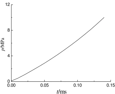
Figure 1. The ignition gas pressure at inlet boundary. Figure 2. The ignition gas temperature at inlet
boundary.
The Heat Transfer between Ignition Gases and the Inner Hole Surfaces
Physical Model and Assumptions
During the flow of ignition flame in the hole, heat transfer takes place between the ignition gases and the wall. The heat transfer includes thermal radiation and convection as well as heat conduction in propellant. The propellant materials are heated to decompose and start burning under certain temperature. In order to simplify calculation, the following assumptions should be set up:
(1) The density, specific heat and thermal conductivity of propellant keep constant during the heat transfer process;
(2) Only the thermal radiation and convection between ignition gases and surfaces are considered during the heat transfer process;
(3) Once the temperatures of propellant surfaces are higher than the ignition temperature, the propellants start to burn. So, the chemical reaction and phase transition of propellant materials are neglected;
(4) The axial heat conduction of propellant is ignored, onlyradial conduction is considered.
Mathematical Model
Under the above assumptions, the heat transfer in propellant can be simplified as transient one-dimensional radial heat conduction with boundary condition of convection and radiation. The heat conduction equation[9,10] within the propellant can be described as follows:
2 2
1
( )
p p p
T T T
a
t r r r
∂ ∂ ∂
= +
∂ ∂ ∂ . (5)
Numerical Scheme
The heat transfer model is a typical parabolic equation, the explicit solution is the simplest method to difference the equation.
1 1 1 1
1
2
1
2 1
[ ]
( ) 2
n n n n n
i i i i i
n n
i i
p p p p p
p p
T T T T T
T T a t
r r i r r
+ − + −
+ = + ∆ − + + −
∆ + ∆ ∆ . (6)
[image:3.612.321.516.70.231.2]1
0 0 2 2 1
2 2 2 2
(1 )
n n n n
j
p p p p
p p p
h t a t a t h t
T T T T
C r r r C r
ρ ρ
+ = − ∆ − ∆ + ∆ + ∆
∆ ∆ ∆ ∆ . (7)
where h is the heat transfer coefficient which includes both convective heat transfer coefficient and radiation heat transfer coefficient.
Calculation Results and Data Analysis
The Flow Properties of Ignition Gases in the Inner Hole
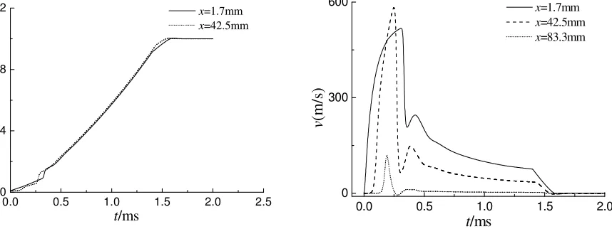
The pressure variation of ignition gas in the inner hole is illustrated in figure 3. It can be found that the pressure fluctuates in initial stage and the overall trend is that the pressure rises first but keeps constant at last. This is because the pressure of ignition gas increases over time, as ignition gas flowing into inner hole, the pressure of different points in hole rises at the same time. The pressure of ignition gas keeps constant after it reached peak value and the pressure of points in inner hole keeps constant at last too.
[image:4.612.97.526.488.649.2]The velocity of ignition gases in the different points is listed in figure 4. Generally, the velocity increases rapidlyat the initial ignition stage and declines rapidly after reaching its peak value. After that there is a small fluctuation. And next moment, the velocity begins to decrease slowly. At last, the flow velocity approaches zero. We can explain it through the variation of pressure. During the initial period, the pressure of ignition gas increases quickly, so does the pressure difference between two neighboring points which makes flow velocity rise rapidly. As ignition gas flowing into the inner hole, the pressure of points in hole begins to rise, the pressure difference starts to reduce and even be opposite to flow direction so that the flow velocity decreases rapidly. Finally, as the flow process achieving balance, the pressure difference equals zero and flow velocity approaches zero too. It is worth noting that the points close to symmetry point have negative velocity which means that gas flows out of the inner hole and this phenomenon is consistent with the hypotheses.
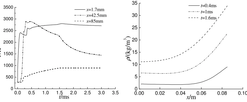
[image:4.612.311.524.490.647.2]Figure 5 shows the curves about the variation of ignition gas temperature. The variation trends of different points are different. But they all approach to a different constant value. More close to the orifice, the bigger the value is.
Figure 6 shows the distribution of ignition gas density at different time (ρ-x cures). As we can see in the figure, more close to the symmetry point, the larger the gas density is.
0.0 0.5 1.0 1.5 2.0 2.5
0 4 8 12
p
/M
P
a
t/ms
x=1.7mm
x=42.5mm
0.0 0.5 1.0 1.5 2.0
0 300 600
v
(m
/s
)
t/ms
x=1.7mm
x=42.5mm
x=83.3mm
0.0 0.5 1.0 1.5 2.0 2.5 3.0 3.5 0
500 1000 1500 2000 2500 3000 3500
T
/K
t/ms
x=1.7mm
x=42.5mm
x=85mm
0.000 0.02 0.04 0.06 0.08 0.10 5
10 15 20 25 30 35
ρ
/(
k
g
/m
3 )
x/m
t=0.4ms
t=1ms
[image:5.612.105.511.73.241.2]t=1.6ms
Figure 5. Temperature variation of ignition gas. Figure 6. Density distribution of ignition gas.
The Temperature of Propellant and the Ignition Procedure
As indicated in the heat transfer model, the temperature of propellant will increases under the heating of heat flux of ignition gases. The temperature of the propellant varies in axis and radius because of the unsteady flow and heat transfer. To study the ignition process of propellant, only the variation and distribution of temperature of inner hole surface of propellant are investigated.
The temperature variation of different points of inner hole surface is showed in figure 7. It can be found that all the temperatures increase quickly in the beginning of heat transfer between ignition gases and propellant, then the increasing slope tend to be flat. These can be explained as that in the initial stage of gases flow and heat transfer, the higher velocity of ignition gases enhances the heat transfer, while in the later stage the heat flux decreases because of the decreasing of velocity and temperature difference. At one moment the temperature decreases with the increasing of axis coordinate. As the flowing of ignition gases from inlet to the end of the hole, the temperature and velocity of ignition gases decrease. Both the decreasing of convection heat transfer or radiation will retard the heating of propellant.
Figure 8 shows the temperature distribution of the inner hole surface of propellant in axial coordinate. The general trend is that the temperature decreases from the inlet to the end.
0.0 0.5 1.0 1.5 2.0 2.5 3.0 3.5 300
350 400 450 500
Tp
/K
t/ms
x=25.5mm
x=42.5mm
x=59.5mm
0.00 0.02 0.04 0.06 0.08 0.10 200
300 400 500 600 700 800 900
Tp
/K
x/m
t=1ms
t=2ms
[image:5.612.122.505.515.668.2]t=3ms
Figure 7. Temperature variation of inner face. Figure 8. Temperature distribution of inner face.
The above simulating results are based on the assumptions that the flame propagation and heat release of ignited propellant are neglected. In fact, the ignition of propellant will be enhanced after the first point is ignited, and the heat transfer in propellant will take a major effect because of the heat release of chemical energy of propellant.
Conclusions
By the numerical simulating of the propagation of ignition flame in the inner hole of perforated propellant grains and the heat transfer between the ignition flame and the surface of inner hole, following results can be generalized:
(1) Due to the unsteady flow of ignition flame in the inner hole of propellant grains, the flow parameters of gases vary with time and coordinate. Generally, the closer to the inlet, the larger the pressure is. The velocity of flame increases rapidly in the beginning, and decreases rapidly after reaching its peak value. The temperatures of ignition gas at different points are different for the time delay of flame propagation.
(2) The temperature of inner hole surface increases with time and decreases along axial coordinate. The propellant will be ignited form the inlet to the end gradually, and the non-simultaneous ignition of the surface will change the combustion properties of propellant, and hence influences the ballistic properties of propulsion.
References
[1] Liu Yu-ping, Li Jin-xin, Yang Zhen, Bo Yu-cheng. Interior Ballistics Analysis and Numerical Simulation of Underwater gun [J]. Journal of Gun Launch & Control, 2007, (4): 30-33.
[2] Ji Xiao-song, Tao Ru-yi, Huang Ming, Wang Hao. Numerical simulation on interior ballistic process of floating engine system in individual tube-shape weapon [J]. Journal of Nanjing University of Science and Technology, 2007, 31(6): 715-718.
[3] Xiao Z, He W, Xu F. Emulation and Calculation of the Burning Surface of 3D Grains of Partially Cut Multi-Perforated Stick Propellant using the Level Set Method[J]. Propellants, Explosives, Pyrotechnics, 2015, 41(1): 148-153.
[4] Lv Bing-feng, Liu You-ping, Dong Feng-yun, Ma Zhong-liang, He Zeng-di, Xiao Zhong-liang. The Mathematical Model of Propellant Actual Combustion Law on the Constant Volume Condition[J]. Chinese Journal of Explosives &Propellant, 2007, 30(6): 72-74.
[5] T. W. H. Sheu, S. -M. Lee. Analysis of Combustion Processes in a Gun Interior Ballistics[J]. International Journal of Computational Fluid Dynamics, 1995, 4(1-2): 57-71.
[6] Fürst J, Furmánek P. An implicit MacCormack scheme for unsteady flow calculations[J]. Computers & Fluids, 2011, 46(1): 231-236.
[7] Bernard R S. A MacCormack scheme for incompressible flow[J]. Computers & Mathematics with Applications, 1992, 24(5): 151-168.
[8] Ali F, Kassar M A. The MacCormack difference scheme and radiation transport[J]. Computer methods in applied mechanics and engineering, 1994, 114(1): 169-176.
[9] Carlomagno I, Sellitto A, Cimmelli V A. Dynamical temperature and generalized heat-conduction equation[J]. International Journal of Non-Linear Mechanics, 2016, 79: 76-82.