HP 9000 Series
300/500
Computers
HP 98700H CE Handbook
Flin-
HEWLETTHP 98700H CE Handbook
for HP 9000 Series 300/500 Computers
Manual Reorder No. 98700-90039
© Copyright 1985 Hewlett-Packard Company
lan-Product Information
II
Environmental/Installation/PM
•
Configuration
I
Troubleshooting
II
Diagnostics
I
Adjustments
II
Peripherals
•
Replaceable Parts
I
Diagrams
11
Reference
II
Printing History
New editions of this manual will incorporate all material updated since the previous edition. Update packages may be issued between editions and contain replacement and additional pages to be merged into the manual by the user. Each updated page will be indicated by a revision date at the bottom of the page. A vertical bar in the margin indicates the changes on each page. Note that pages which are rearranged due to changes on a previous page are not considered revised.
The manual printing date and part number indicate its current edition. The printing date changes when a new edition is printed. (Minor cor-rections and updates which are incorporated at reprint do not cause the date to change.) The manual part number changes when extensive technical changes are incorporated.
Product Description
1
I
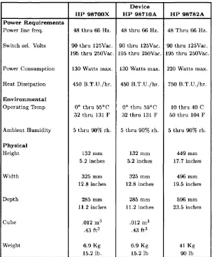
HP 98700H Specifications
Table 1-1. HP 98700H Specifications
Device
HP 98700X HP 98710A HP 98782A
Power Requirements
Power line freq. 48 thru 66 Hz. 48 thru 66 Hz. 48 Thru 66 Hz.
Switch sel. Volts 90 thru 125Vac. 90 thru 125Vac. 90 thru 125Vac.
195 thru 250Vac. 195 thru 250Vac. 195 thru 250Vac.
Power Consumption 130 Watts max. 130 Watts max. 220 Watts max.
Heat Dissipation 450 B.T.D./hr. 450 B.T.D./hr. 750 B.T.D./hr.
Environmental
Operating Temp 0° thru 55°C 0° thru 55°C 10 thru 40 C
32 thru 131 F 32 thru 131 F 50 thru 104 F
Ambient Humidity 5 thru 90% rho 5 thru 90% rho 5 thru 90% rho
Physical
Height 132 mm 132 mm 449mm
5.2 inches 5.2 inches 17.7 inches
Width 325 mm 325 mm 496mm
12.8 inches 12.8 inches 19.5 inches
Depth 285 mm 285 mm 596mm
11.2 inches 11.2 inches 23.5 inches
Cube .012 m3 .012 m3
.43 ft3 .43 ft3
Weight 6.9 Kg 6.9 Kg 41 Kg
15.2 lb. 15.21b 90lb
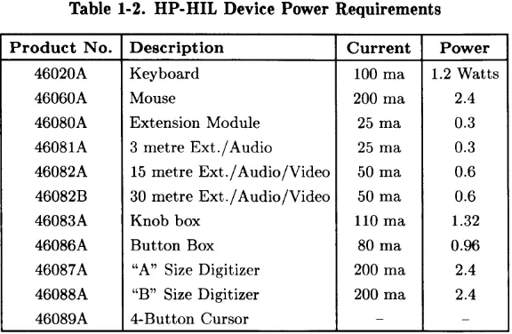
[image:5.397.66.369.135.503.2]HP·HIL Power Loading
HP-HIL, the Hewlett-Packard Human Interface Loop is the HP stan-dard for interfacing terminals, workstations, and personal computers to their human-input devices. HP-HIL provides a simple, asynchronous serial communication protocol that enables the user to select a set of input devices, connect them to a computer product, and work with any application program with ease.
HP-HIL used with the HP 98700 is limited to seven devices on one Loop, and the power available is 12 watts (+12 volts at 0.5 Amp). Do not exceed this value. To assist you in determining if the devices you want to use will overload the Loop or not, here is a table listing the individual device power requirements:
Table 1-2. HP-HIL Device Power Requirements
Product No. Description Current Power 46020A Keyboard 100 rna 1.2 Watts
46060A Mouse 200 rna 2.4
46080A Extension Module 25 rna 0.3 46081A 3 metre Ext./ Audio 25 rna 0.3 46082A 15 metre Ext./ Audio/Video 50 rna 0.6 46082B 30 metre Ext./ Audio/Video 50 rna 0.6
46083A Knob box 110 rna 1.32
46086A Button Box 80 rna 0.96
46087A "A" Size Digitizer 200 rna 2.4 46088A "B" Size Digitizer 200 rna 2.4
[image:6.396.36.324.234.422.2]-As stated above the Loop is limited to seven devices. Another restriction is the length of cable between each device. Maximum distance is 2.4 me-tres1 device to device1 with a total of 21 metres maximum. This does not
include the 15 metre and 30 metre extension options that are available. Overloading the Loop will result in a blown fuse on the Loop interface circuitry. The troubleshooting procedure is to replace the assembly that contains the Loop interface circuitry and then1 before restoring power
to the system1 refigure the power loading on the Loop. If the loading is
too highl the Loop will have to be unloaded by removing devices until the power loading is in the proper range.
Documentation
Documentation for the HP 98700H is contained in four documents:
98700-90001 98700-90030 98700-90039 98782-90001 98782-90030 98782-90039 97089-90039 98680-90039
Installation Guide for the graphics display station.
Hardware Support Document for the graphics dis-play station.
CE Handbook Insert for the graphics display sta-tion ..
Installation Guide for the monitor.
Hardware Support Document for the monitor.
CE Handbook Insert for the monitor.
HP-UX CE Handbook1 Series 500.
HP-UX CE Handbook1 Series 200.
Other documents that will be helpful are the installation and hardware support documents for the computer system the HP 98700H is a part of.
Environmental/Installation/
Preventive Maintenance
2
Introduction
Device
HP 98700X HP 98710A HP 98782A Environmental
Operating Temp 0° thru 55°C 0° thru 55°C 10 thru 40 C
32 thru 131 F 32 thru 131 F 50 thru 104 F
Ambient Humidity 5 thru 90% rho 5 thru 90% rho 5 thru 90% rho
Physical
Height 132 mm 132 mm 449 mm
5.2 inches 5.2 inches 17.7 inches
Width 325 mm 325 mm 496 mm
12.8 inches 12.8 inches 19.5 inches
Depth 28.5 mm 285 mm 596 mm
11.2 inches 11.2 inches 23.5 inches
Cube .012 m3 .012 m3
.43 ft3 .43 ft3
Weight 6.9 Kg 6.9 Kg 41 Kg
15.2 lb. 15.21b 90lb
Site Preparation
Refer to the HP 9000 Series 200/300/500 Site Preparation Document, part number 09000-90041, to assist you in preparing for the installation of the HP 98700H Graphics Display Station. Refer to the lists in Chapter 1 for specific power and environmental requirements.
Cable Restrjctions
RGB Cables
There are two styles of RGB cables supported with the display station:
• A single, three metre cable with three shielded conductors. Each conductor is color coded for RG B and terminated with BN C conec-tors .
• A set of three co-ax cables with BNC connectors. One for each color. There is no real limitation on the length of the cables other than loading. Due to this loading, the maximum supported length is 30 metres. Two lengths are available from Hewlett-Packard, 15 metres and 30 metres.
Series 300110 Interconnect Cable
The Series 300 interconnect cable connects the Model 310/320 to the HP 98700. The cable connector key projects outward near the top from each end of the connector shell. Ensure that this is UP when connecting to the I/O card or the HP 98700.
Series 500 Display Station Buffer Interconnect Cable
The Display Station Buffer Interconnect cable (p/n HP 98700-61583) connects the Model 550 to the HP 98700.The interconnect cable is in-stalled by an HP Customer Engineer or HP trained engineer.
HP·HIL Cables
HP-HIL is limited to seven devices on one loop, and the power available is 12 watts (+12 volts at 1 Amp). Do not exceed this value. Another restriction is the length of cable between each device. Maximum distance is 2.4 metres, device to device, with a total of 16.8 metres maximum. This does not include the 15 metre and 30 metre extension options that are available.
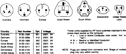
Power Cables
The power cord shipped with your graphics display station should be the appropriate one for your location. (See the diagram below that pictures the different power cord options.) If your power cord needs replacement, refer to the diagram and order an exact replacement.
@
Q
G3
&§J
[QJ
~
~
~
• •
~ ~•
N l ~ ~ N lSwitzerland United States Australia Denmark Europe Great Britain South Africa 120V
Country Part Number Power cords supplied by HP have polarities matched to the ustralia 8120-1369 power-input socket on the computer:
• L = Line or Active Conductor (also called "live" or Denmark 8120-2956 912 250V, 6A "hot")
Europe 8120-1689 902 250V, 6A • N = Neutral or Identified Conductor Great Britain 8120-1351 900 250V, 6A • E = Earth or Safety Ground South Africa 8120-4211 917 250V, lOA
Switzerland 8120-2104 906 250V, SA NOTE: Plugs are viewed from connector and. Shape of molded United States 8120-1378 903 12OV, lOA plug may vary within country.
Figure 2-1. Power Cord Options
Environmental/Installation/Preventive Maintenance 2-3
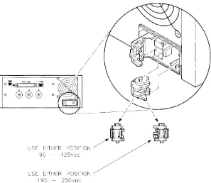
[image:11.399.85.354.229.345.2]Line Voltage and Fuse Selection
CAUTION
BE SURE THE LINE VOLTAGE SELECT SWITCH IS SET CORRECTLY BEFORE CONNECTING THE POWER CORD. IF THE SWITCH IS SET FOR 95-125 VOLTS AND THE POWER SOURCE IS 195-250 VOLTS. SERIOUS EQUIPMENT DAMAGE WILL RESULT.
0io~~ 0
Q)
®®®
0USE
195 - 250Vac
[image:12.398.32.329.202.460.2]WARNING
BEFORE REMOVING THE FUSE HOLDER CAP TO CHECK OR CHANGE THE FUSE, BE SURE THAT ALL POWER IS DISCON-NECTED FROM THE GRAPHICS DISPLAY STATION.
CAUTION
REPLACEMENT FUSES MUST BE RATED FOR 250 VOLTS, AND MUST NOT EXCEED THE CURRENT RATING INDICATED ON THE REAR PANEL. OTHERWISE EQUIP-MENT DAMAGE OR FIRE WILL RESULT.
Installation
The HP 98700H Graphics Display Station may be installed as part of a new computer system, or it may be installed as an enhancement to an existing system. In either case the computer must be installed and its performance verified first. Follow the instructions in the computers In-stallation Guide, and accomplish the self tests. When the computer and its required memory and peripherals are known to be working properly, then proceed with the display station installation.
Required Tools
Installation of the display station does not require special tools. How-ever, here is a list of tools that will be useful:
• Pozidrive@ screwdriver, number 1, 3 inches long.
• Pozidrive@ screwdriver, number 2, 4 inches long.
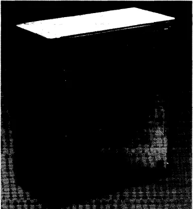
Connecting the HP 98710A
1. Ensure that the HP 98700 is disconnected from its power source.
2. Remove the cover plate on the front bottom of the HP 98700 and place it in the storage position provided. Plate must be installed over the connector for the HP 98700 to operate by itself. See figure 3-1.
3. Move the locking mechanism on top of the HP 98710A to the rear.
4. Set the HP 98700 on top of the HP 98710A, ensuring that the guide pins enter the guide pin sockets.
5. Gently but firmly press the HP 98700 down until the connector engages and seats.
6. Slide the locking mechanism forward to lock the two together.
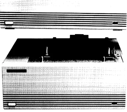
Figure 2-4. Removing the Cover Plate
[image:15.398.123.315.263.471.2]-=
[image:16.396.73.283.84.270.2]Series 300 Installation
o
SW1
CJ
SW2
L
III
III
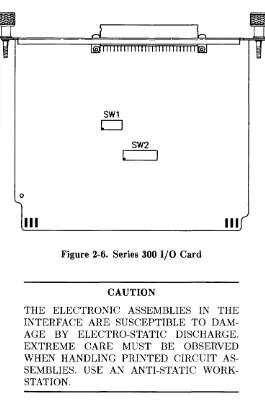
Figure 2-6. Series 300 I/O Card
CAUTION
THE ELECTRONIC ASSEMBLIES IN THE INTERFACE ARE SUSCEPTIBLE TO DAM-AGE BY ELECTRO-STATIC DISCHARGE. EXTREME CARE MUST BE OBSERVED WHEN HANDLING PRINTED CIRCUIT AS-SEMBLIES. USE AN ANTI-STATIC WORK-STATION.
Environmental/Installation/Preventive Maintenance 2-9
[image:17.397.85.350.80.485.2]Carefully remove the HP 98287 A I/O card from its protective bag.
There are two switches on the I/O card used to set the locations that the HP Human Interface LOOP (HP-HIL) and the HP 98700 will respond to. Switch 1 is a five section switch that sets the select code of the HP 98700 HP-HIL. Switch 2 is an eight section switch that sets the location of the HP 98700 control space and frame buffer. For switch location see Figure 3-5.
Pascal and BASIC operating systems will not support HP-HIL through the HP 98700H. HP-HIL must be installed through the HP-HIL connec-tor in the rear panel of the Series 300 computer. Refer to the Installation Guide for your computer for details.
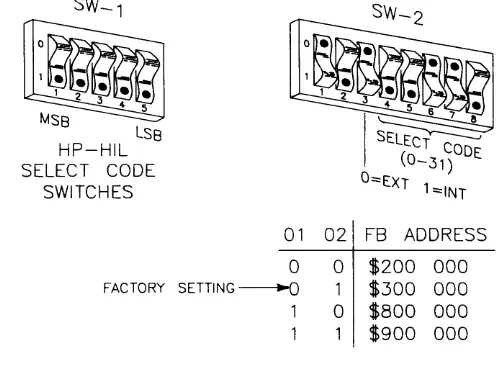
1. Set the switches as desired. See Figure 2-7.
LSB
HP-HIL SELECT CODE
SWITCHES FACTORY 01 0 SETTING~ 1
02 FB ADDRESS 0 $200 000 1 $300 000 0 $800 000 $900 000
[image:18.396.50.300.245.428.2]2. Install the I/O card in any DIO slot in the backplane of the com-puter or any slot in the epander. Ensure that it is fully seated.
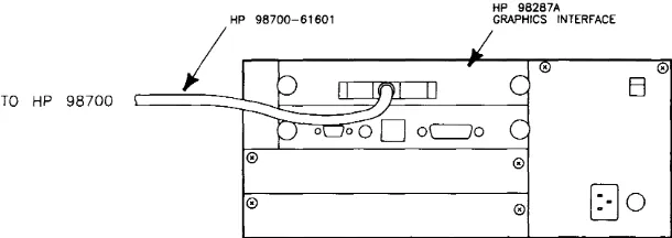
3. Connect the interconnect cable to the I/O card connector. The cable connector key projects outward near the top from each end of the connector shell. Ensure that this is UP when connecting to the I/O card or the HP 98700.
HP 98287A HP 98700-61601 GRAPHICS INTERFACE
I
0El
TO HP 98700
0 0
0 0
[JO
Figure 2-9. Connecting the I/O Interconnect Cable
4. Connect the other end of the cable to the HP 98700.
Continue with the seeton "'Installing the HP-HIL Accessories".
[image:19.401.69.374.153.261.2]Series 500 Installation
CAUTION
THE ELECTRONIC ASSEMBLIES IN THE DISPLAY STATION ARE SUSCEPTIBLE TO DAMAGE BY ELECTRO-STATIC DIS-CHARGE. EXTREME CARE MUST BE OB-SERVED WHEN HANDLING PRINTED CIR-CUIT ASSEMBLIES. USE AN ANTI-STATIC WORKSTATION.
The HP 98288A Display Station Buffer card is installed into the Proces-sor Stack area of the Series 500 Model 550 computer. There are 12 card slots in the processor stack area. The DSB's must be installed in slots 4 through 7 only and the first DSB must be in slot 4. Slots 1 through 12 contain in order;
• 1 contains the CPU
• 2 contains the lOP
• 3 contains RAM
• 4 thru 7 contains either DSB or RAM.
• 8 thru 12 contains RAM.
The processor stack configuration must be contiguous (that is, no empty slots between cards).
There are no configuration switches on the DSB card.
Installing the Hp·HIL Accessories
The human interface to the Series 300/500 computer system is through the HP-HIL of the HP 98700. Ensure that you do not exceed 1000 rna total current on the HP-HIL loop. In any case, HP-HIL will address no more than seven devices on one loop.
CAUTION
HP-HIL SUPPORTS UP TO 12 WATTS, ON THE LOOP. IF THE LOOP IS OVERLOADED, THE LOOP MAY FAIL DUE TO AN OPEN FUSE IN THE HP-HIL CIRCUITRY.
Pascal and BASIC operating systems will not support HP-HIL through the HP 98700H. HP-HIL must be installed through the HP-HIL connec-tor in the rear panel of the Series 300 computer. Refer to the Installation
Guide for your computer for details.
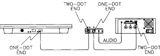
HP 46081A HP·HIL Extension/Audio Module
The HP-HIL Extension/Audio Module consists of three items:
• The module box
• A 2.4 metre (8-foot) HP-HIL cable
• A 2.4 metre (8-foot) audio cable
Installing the Module
Select a location for the module, install the Dual Lock fastener pad and attach the module to the pad.
Connecting the HP-HIL Extension/ Audio Module
CAUTION
THE HP-HIL CABLES ARE NOT END FOR END INTERCHANGEABLE. THE END MARKED WITH TWO DOTS MUST BE CON-NECTED INTO A CONNECTOR WITH THE SAME NUMBER OF DOTS. EQUIPMENT DAMAGE WILL RESULT IF THIS PRECAU-TION IS NOT FOLLOWED.
To install the HP-HIL Extension/ Audio Module~ follow this procedure:
1. Ensure that the system has power removed.
2. Plug the one-dot end of the HP-HIL interconnect cable into the one-dot connector on the extension module.
3. Plug the two-dot end of the cable into the two-dot, HP-HIL con-nector on rear panel of the HP 98700.
4. Plug the one-dot end of the coiled HP-HIL keyboard cable into the one-dot connector on the rear of the keyboard.
6. Finally, Connect the furnished audio cable between the HP-HIL Extension/ Audio Module and the audio connector near the HP-HIL connector on the rear panel of the HP98700. The ends of the audio cable are interchangeable.
ONE-DOT
END
TWO-DOT
END
ONE-DOT
END
'---_ _ _ _ _
--' TWO - DO T
END
Figure 2-10. Connecting the HP-HIL Extension/Audio Module and Keyboard
The Extension Module and Keyboard are now ready for use.
[image:23.399.65.373.115.223.2]Installing the HP 98701 A
1. Remove the top cover by loosening the two screws at the lower rear of the back panel. Lift the rear of the cover and slide to the rear until clear of the front panel. Carefully set the top cover aside.
2. Loosen the four captive screws all the way.
3. Remove the two flathead screws near the top sides of the rear panel.
4. Swing the rear panel down to gain access to the card cage.
5. Remove the Color Map card from the bottom slot.
6. Remove the HP 98701A from its protective bag and insert it into the card slot above the color map card (the second slot from the bottom).
7. Reinstall the Color Map card in the bottom slot
8. Swing the rear panel up and secure it with the four captive screws.
9. Install the two flathead screws that secure the rear panel to the side frames.
Turn On Procedure.
CAUTION
SHOULD A SINGLE, BRIGHT,HORIZONTAL LINE APPEAR ACROSS THE CENTER OF THE CRT, IMMEDIATELY TURN THE MON-ITOR OFF TO AVOID DA~IAGE. THEN CON-TACT YOUR HP SALES AND SERVICE OF-FICE FOR SERVICE ASSISTANCE.
First, turn the HP 98700H ON. Wait ten seconds and then turn the rest of the system ON. If the HP 98700H is turned ON last it may reset the system and possibly result in a system error. The power lights should light up and the monitor should display information after a few seconds. You can be assured the system is at least operational if:
1. You turn-on all parts of the system and the power-on indicators light.
2. After a few seconds wait, the monitor starts displaying information.
3. Your system loads and runs an operating system and/or demo program.
Where to Go Next
After the HP 98700H is installed and you are assured that it is function-ing properly, load the HP-UX Operatfunction-ing System. Refer to the HP-UX
Configuration
3
HP 98700H Series 300 Interface
SW1
CJ
SW2
L
o
[image:27.398.67.357.56.356.2]III
III
Figure 3-1. Series 300 Interface Card
There are two switches (Sw-l and Sw-2) on the I/O card. These switches set the select codes for the HP-HIL interface of the HP 98700 and for the frame buffer RAM control space of the HP 98700. Switch 1 is a five section switch that sets the HP-HIL. Switch 2 is an eight section switch that sets the location of the HP 98700 control space and frame buffer.
Sw-l sets the external select code (0 to 31. Note: Select Codes 0-7 are reserved for internals, and Select Code 9 is for RS-232.) that the HP-HIL of the HP 98700 will respond to. Sw-l, 1 is the msb and the SW-l, 5 is Isb. Pushing a switch towards the back plate sets the bit to 0, pushing it away from the back plate sets the bit to 1. Factory setting is Select Code 31.
---
---Sw-2 sets the HP 98700 control space select code and the frame buffer address. The Sw-2~ 1 and 2 set the start address of the 1M byte frame buffer as shown in Figure 3-2. Factory setting is address hex300000 and should be left at this address. The Sw-2, 3 selects whether the HP 98700 control space is at internal address hex 560000 or at an external select code as set by Sw-2, 4 through 8. If Sw-2, 3 is a 1, the HP 98700 is set to internal address. If Sw-2, 3 is a 0, the HP 98700 set to an external select code. Factory setting for Sw-2, 3 is external and Sw-2, 4-8 is Select Code 25.
SW-1
LSB
HP-HIL SELECT CODE
SWITCHES
FACTORY
01
0
SETTING ---.0
1
02 FB ADDRESS
0 $200 000 1 $300 000 0 $800 000 $900 000
Figure 3-2. Setting the Switches
3. Install the I/O card in any DIO slot in the computer or any slot of the expander. Ensure that it is fully seated.
As with all DIO cards, no two select codes may be the same. If
[image:28.398.55.301.187.365.2]HP 98700H Series 500
Display Station Buffer
III
D D
D D
D D
D D
Figure 3-3. Series 500 Display Station Buffer
[image:29.397.94.340.120.335.2]The Series 500 Display Station Buffer (DSB) card is installed into the Processor Stack area of the Series 500 Model 550 computer. The DSB is normally installed at the factory, however, you may have to install it as an upgrade. There are 12 card slots in the processor stack area. The DSB must be installed in slots 4 through 6 only and the first DSB must be in slot 4. Slots 1 through 12 contain in order;
• l=CPU
• 2=IOP
.3=RAM
• 4 thru 7=DSB or RAM.
• 8 thru 12=RAM.
The processor stack configuration must be contiguous (that is, no empty slots between cards).
Troubleshooting
4
Introduction
The HP 98700 is installed between a computer and the HP 98782A color monitor and your job is to determine whether the problem is in the computer, the Graphics Interface card or Display Station Buffer card, the Display Controller, the Graphics Accelerator if present, the Monitor, or in the HP-HIL (Human Interface Loop).The 98700H graphics monitor station consists of:
HP 98287A
HP 98288A
HP 98700
HP 98710A
HP 98782A
HP 46020A
HP 46081A
98700-61601
98700-61602
HP 98290A
Power Cords
Series 300 Graphics Interface (GIO) card.
Series 500 Display Station Buffer (DSB) card.
HP 9000 Display Controller.
HP 9000 Graphics Accelerator.
High Resolution, 19 inch Color Display.
HP -HIL Keyboard.
HP-HIL Extension/Audio Module including cables.
Interconnect cable to connect the HP 98287 A to the 98700.
Interconnect cable to connect the HP 98288A to the 98700.
Shielded RGB cables To connect the 98700 to the 98782A.
To connect the HP 98700, the HP 98710A, and the HP 98782A to the power source.
This Chapter discusses how to isolate a faulty assembly. Troubleshooting is broken into two sections:
• Troubleshooting the 98700, including the I/O cards, and
• Troubleshooting the 98710A.
Some troubleshooting hints for the 98782A monitor are also presented here.
Troubleshooting
Tools Required
• Number 1 POZIDRIV screwdriver, 3 inches long.
• Number 2 POZIDRIV screwdriver, 4 inches long.
• Standard .250 inch flat tip screwdriver, 4 inches long.
• YOM, HP 3435A or equivalent.
• Test Tools Manual, 09800-90001.
• Series 300 Test Tool Set. 3 inch, HP 09800-12300 5 inch, HP 09800-12500
• HP-UX System Functional Tests.
Initial Troubleshooting
Spend a little time and question the user about the problem. What are the symptoms? When did the problem first occur? Think about what the problem is and what it is not. Then go look yourself. What symp-toms do you notice? Call on past experiences and try to remember what section caused that problem before. A little thought in the beginning can save you countless minutes of wasted motion.
The following sections lead you through some tests that you can do with minimum equipment.
Preliminary Troubleshooting
Here are some quick checks that can be made as the computer/Graphics Display Station (GDS) system is turned ON.
Check that the Line Select Switch on each rear panel is in the correct position, and turn the computer/GDS system ON in this order:
1. Turn ON the System Disc drive,
2. Turn ON the HP 98782A Monitor. Listen for the High Voltage crackle that indicates the HV supply in the monitor is working.
3. Turn ON the HP 98710A, if present.
4. Wait for the monitor to warm up and turn ON the HP 98700. Observe that the monitor screen "flashes" as the 98700 is turned ON.
5. Finally, turn the computer ON.
Troubleshooting Charts
Here are some troubleshooting charts to assist you in troubleshooting the 98700 Display station.
Chart "A".
TURN SYSTOot ON H700H FIRST
'IloI£N CPU
Figure 4-1. Troubleshooting Chart "A"
[image:35.399.107.334.145.495.2]Troubleshooting Chart A (see Figure 4-1) leads you through some pre-liminary steps to determine if the computer (CPU) is working. This is determined thru the BootROM self tests. The host computer must be operational before you can determine what is wrong with the 98700H.
After replacing each faulty assembly, check to see if the power on lights come ON. When the power on lights all light continue with step 4. If
Chart "B"
FORCE NEW
SYSTEM CONSOLE
REFER TO
SYSTEM CONFlCURAllON
NO
T/S IN171QA
RETURN TO
FlOW CHART A
ENlP AT D
Figure 4-2. Troubleshooting Chart "B"
If Chart A directed to this chart, it is time to start introducing changes into the system to locate the faulty assembly. Follow these steps: (See Figure 4-2)
If messages are not displayed on next console, force a new system con-sole by removing the 98700(H) from the system. Refer to the system configuration for this system.
[image:37.398.127.327.69.401.2]Chart "C"
ell8782A
e 1 FlWotE BUffER
1ST nWE THROUGH 2ND TlME THROUGH
T/5 HP 118782A
CHECK OUTPUT
OF 18700A OSCIUDSCOPE
[image:38.396.64.298.58.497.2]If step Chart B directed you to this chart, it is time to force a minimum system. Follow this procedure:
Troubleshooting Oddities
An unexpected trouble that can occur is a dead keyboard. If the com-puter fails to enter data from the keyboard, substitute a new keyboard and try again. If the computer still fails to enter data, the prohlem is in the HP-HIL loop. Suspect the HP-HIL circuitry in the GDS, the interconnect cable, or the HP-HIL/ Audio Extension Module.
Diagnostics
5
Here are some quick checks that can be made as the computer/Graphics Display Station (GDS) system is turned ON.
Check that the Line Select Switch on each rear panel is in the correct position, and turn the computer/GDS system ON in this order:
1. Turn ON the System Disc,
2. Turn ON the HP 98782A Monitor. Listen for the High Voltage crackle that indicates the HV supply in the monitor is working.
3. Wait for the monitor to warm up and turn ON the HP 98700. Observe that the monitor screen "flashes" as the 98700 is turned ON.
4. Turn ON the HP 98710A~ if present.
5. Finally, turn the computer ON. HP Model 310/320 or Model 550.
In any case the computer and its peripherals must be operating properly before attempting to troubleshoot the HP 98700H.
Series 500 Multi-seat System
Use the turn-on procedure listed above and observe that the monitor screen "flashes" as the 98700 powers up. If the screen does "flash" then turn the computer ON. These loader messages should appear on the monitor of the Graphics Display Station (GDS) whose DSB is in the lowest numbered slot (=GDSO):
Loader revision 4.1 Testing Memory ... Looking for a System ...
HP-UX Model 530/540 Release 5.00 (97089C)
Load Done
If the loader messages do not appear, check the other two GDS monitors.
If the messages appear on one of the other GDS monitors (GDSI or GDS2) then the DSB for GDSO or its interconnect cable is defective.
(If the loader messages appear on the monitor for GDS2, then the DSB cards or cables for GDSO and 1 have a problem.) If the loader messages appear on a terminal connected to either the 27130A (MUX) card or 27128A (ASI) card, then that indicates that the loader ROM was unable to talk to any GDS in the system because of DSB card or cable problems.
If the system must be powered down do so during the "Testing Memory" period.
Gsft, Graphics System Functional Tests
With the HP-UX operating system loaded and running, log on to the system and run the Graphics System Functional Tests (Gsft) of the
CE.utilities (super user capability not required). The path name is:
/usr/CE.utilities/Gsft
and press IRETURNI. Note the upper and lower case letters.
For a more complete discusion on UX CE.utilities, refer to the HP-UX CE Handbook (part number 98680-90039) Chap 5, or the HP-HP-UX System Administrator document, part number 98680-90011.
For help, type:
./help
and press IRETURNI.
To run the HP 98700/98710A/98782A tests. type:
./test98700
and press IRETURNI. The following menu will appear on screen:
98700 Test Utilities
0) Exit
1) Short Test
2) Long Test
3) 98710A Graphics Accelerator Test 4) CRT Patterns
Please enter the # corresponding to the test and then press I RETURN I.
The monitor will then display:
Which GPH Slot do you want to test (0-3)?
Enter the slot number and press IRETURNI.
Short Test patterns
Select the #1 test from the menu. The monitor screen will display several patterns to indicate that tests are taking place. If the screen goes dark and stays dark the test has failed or the system has failed. Refer to the HP-UX Series 500 CE Handbook for recovery procedure. If
the test is passed a message similar to the following appears:
The 98700 in pos 0 passed its test. 1 device was found in the HP-HIL lOop.
The HP-HIL part of the message will change depending on what HP-HIL configuration and accessories you have on the loop.
If the test is failed a message similar to the following appears:
Test failed. Suspect the 665XX board. 1 device was found on the HP-HIL lOop.
where 665XX denotes a board that is probably causing the fault. The board is designated by the suffix of the part number:
66583 66570 66573 66574 66572 66572 66577 66576
No. of devices
Display Station Buffer
CRT Control
Color Map, discrete.
Color Map, Neried
Frame Buffer, Top slot
Frame Buffer. 3rd slot
Transform Engine, 98710A
Scan Converter, 98710A
Long Test patterns
Select #2 test from the menu. If the test is passed a message similar to the following appears:
The 98700 in pos 0 passed its test. 1 device was found in the HP-HIL loop.
If the test is failed a message similar to the following appears:
Test failed. Suspect the 665XX board. 1 device was found on the HP-HIL loop.
98710A Graphics Accelerator Test
Select #3 test from the menu. If the test is passed a message similar to the following appears:
The 98700 in pos 0 passed its test. 1 device was found in the HP-HIL loop.
If the test is failed a message similar to the following appears:
Test failed. Suspect the 665XX board. 1 device was found on the HP-HIL loop.
CRT Patterns
Select #4 from the menu. The monitor screen will display a new menu of patterns to be used for allignment of the monitor. Each pattern will stay on screen untill you select a new pattern. Refer to the HP 98782A Hardware Support Document, part number 98782-90030 for monitor alignment procedure.
Adjustments
6
There are no adjustments for the HP 98700j98710A. Adjustments for the
HP 98782A are contained in the 98782A Hardware Support Document, part number 98782-90030.
Peripherals
7
Table 7-1. HP-HIL Devices
Product No. Description
46020A Keyboard 46060A Mouse
46080A Extension Module 46081A 3 metre Ext. / Audio 46082A 15 metre Ext./ Audio/Video 46082B 30 metre Ext./ Audio/Video 46083A Knob box
46086A Button Box 46087A "A" Size Digitizer 46088A "B" Size Digitizer 46089A 4-Button Cursor
[image:49.397.115.317.82.288.2]Replaceable Parts
8
Introduction
Here are lists of replacement parts and exchange assemblies and hard-ware components included in the peripheral.
Part numbers in the form xxxxx-69xxx refer to rebuilt assemblies that are available on an exchange basis. Numbers in the form xxxxx-66xxx, -67xxx, or -68xxx refer to new assemblies. All PC assemblies listed are fully loaded boards. Empty PC boards are not available.
The HP 98700 and the HP98710A share some common assemblies. In the following tables, only those parts that are specific for either are identified, otherwise, the assemblies will interchange.
For HP 98782A monitor parts, refer to the Hardware Support Document for the monitor. Part number is 98782-90030.
Table 8-1. HP 98700H Assemblies
Exchange or HP Part No. Qty Used Description Non-Exchange
98700-90001 1 98700 Installation Man. Non-Exch. 46020A 1 ASCII ITF Keyboard Non-Exch
46060A 1 HP-HIL Mouse Non-Exch
46081A 1 Buffer Box/Speaker Exch. 98700-66501 1 Backplane Ass'y, 98700 Non-Exch. 98700-66502 1 Backplane Ass'y, 98710 Non-Exch. 98700-66551 1 Post Regulator Non-Exch. 98700-69570 1 CRT Controller, 98700 Exch. 98700-69572 1 Frame Buffer Ass'y, 98700 Exch. 98700-69574 1 Color Map, 98700 Exch. 98700-69576 1 Scan Converter, 98710 Exch. 98700-69577 1 Transform, 98710 Exch. 98700-69582 1 Series 300 Interface Exch. 98700-69583 1 Series 500 Interface Exch. 09817-66552 1 Power Supply Non-Exch. 98700-61602 1 Interconnect Cable Non-Exch. 98700-61603 1 RGB Cable, 3 Metre Non-Exch. 46060-60001 1 Cable, ITF Keyboard Non-Exch. 46060-xxxxx 1 Ball, Mouse Roller
46080-84300 1 Lock, Dual Non-Exch.
Fuse
HP Part No. Description
[image:52.398.22.336.53.337.2]Hardware Parts List
Here is a list of part numbers for selected hardware items used in the HP
98700H display subsystem. Hardware and cabinet parts listed in Table 8-2 are shown in figures 8-1 and 8-2, 98700H exploded views 1 and 2.
Table 8-2. Mechanical Hardware Part Numbers Front Panel Assembly
HP Part No. Qty Used Description
09817-04102 1 Sub-Panel, Front, Metal 09817-60201 1 Panel Assembly, Front, Plastic 09817-47700 1 Light Pipe
09817-61602 1 LED Cable Assembly 1450-0625 1 Retainer, LED
0624-0450 4 8-16x.375 Screw, Self tap
Rear Panel Assembly
HP Part No. Qty Used Description
98700-00202 1 Panel, rear 3160-0398 1 Fan, DC 3160-0309 1 Finger Guard
0515-0219 4 M3x6 Screw, Flat head
Chassis Assembly
HP Part No. Qty Used Description
0403-0427 2 Foot, Bumper 1400-0249 3 Cable Tie 09121-48303 2 Foot, Molded 09817-04104 1 Plate, Top
98700-04105 1 Air Deflector, 98710A only 09817-64104 1 Top Cover, 98700
98700-67904 1 Top Cover Ass'y, 98710
[image:53.398.77.357.132.429.2]M3 X
09817-64104
TOP COVER ASSY
TOP PLATE
98700-66502
BACKPLANE ASSY
~
0515-0077 M3 X 0.5 FH
09817-66552
POWER SUPPLY
09817-04102
SUB PANEL
09817-60201
[image:54.396.50.318.48.527.2]98700-04105
AIR DEflECTOR
98700-67904
TOP COVER ASS'(
1013 X 6 SCREW PANHfAD 2 REQ'D
98700-66502
BACK~E ASS'(
98700-00203
REAR PANEL
3160-0398
fAN
3160-0309
fiNGER GUARD
98700-66551
\13 X 0.5 FH 3 REQ'D
09817-66552
POWER SUPPLY
09817-04102
SUB PANEL
09817-60201
fRONT PANEL
0515-0077 2 REQ'D
Figure 8-2. 98710H Exploded View 2
[image:55.398.65.375.73.468.2]Diagrams
9
Introduction
No additional diagrams are contained in this handbook. Refer to the HP 98700H Hardware Support Document (part number 98700-90030) and HP 98782A Hardware Support Document (part number 98782-90030) for diagrams. other Diagrams that will be helpful.
Reference
10
Introduction
Reference material such as operating notes, maintenance records, notes on specific operating methods, anu other material may be kept here.
Service Notes
11
Introduction
Here is a place to keep application notes, service notes, and personal notes you may wish to keep.