University of Huddersfield Repository
Tran, Van Tung, Yang, BoSuk and Oh, MyungSuckAn application of decision trees method for fault diagnosis of induction motors Original Citation
Tran, Van Tung, Yang, BoSuk and Oh, MyungSuck (2006) An application of decision trees method for fault diagnosis of induction motors. In: International joint workshop, 2006, Yokohama, Japan.
This version is available at http://eprints.hud.ac.uk/id/eprint/16564/
The University Repository is a digital collection of the research output of the University, available on Open Access. Copyright and Moral Rights for the items on this site are retained by the individual author and/or other copyright owners. Users may access full items free of charge; copies of full text items generally can be reproduced, displayed or performed and given to third parties in any format or medium for personal research or study, educational or notforprofit purposes without prior permission or charge, provided:
• The authors, title and full bibliographic details is credited in any copy; • A hyperlink and/or URL is included for the original metadata page; and • The content is not changed in any way.
For more information, including our policy and submission procedure, please contact the Repository Team at: [email protected].
An Application of Decision Tree Method for Fault Diagnosis
of Induction Motors
Van Tung Tran
1,a, Bo-Suk Yang
1,b, Myung-Suck Oh
1,c1
School of Mechanical Engineering, Pukyong national University,
San 100, Yongdang-dong, Namgu, Busan 608-739, South Korea a
[email protected], b [email protected], [email protected]
Keywords: Decision trees; Classification; Fault diagnosis; Induction motors
Abstract. Decision tree is one of the most effective and widely used methods for building classification model. Researchers from various disciplines such as statistics, machine learning, pattern recognition, and data mining have considered the decision tree method as an effective solution to their field problems. In this paper, an application of decision tree method to classify the faults of induction motors is proposed. The original data from experiment is dealt with feature calculation to get the useful information as attributes. These data are then assigned the classes which are based on our experience before becoming data inputs for decision tree. The total 9 classes are defined. An implementation of decision tree written in Matlab is used for these data.
Introduction
In industrial plants, the use of induction motors has increased in these last decades as industrial prime mover to drive pumps, compressors, fans, and etc. due to their reliability and simplicity in construction. Although induction motors are reliable, they are subjected to some modes of unexpected faults. The faults may be inherent in the machine itself or operating conditions [1]. The faults of induction motors may yield drastic consequences for an industrial process. These faults are related to increasing costs, and worsening process safety conditions and final product quality. Therefore, the necessity of fault diagnosis of induction motors is received considerable attention in recent years.
The most frequent faults of induction motors are summarized the as follow [2]:
Opening or shorting of one or more of a stator phase winding
Broken rotor bar or cracked rotor end-rings
Static or dynamic air-gap irregularities
Bearing failures
Several methods has successfully proposed for fault diagnosis of induction motors such as applying Dampster-Shafer theory [1], resorting to spectrum analysis of machine line current and used extended Park’s vector approach to detect of inter-turn short circuits in the stator winding [2], combining neural networks with fuzzy logic and forming a fuzzy back propagation network for identifying the present condition of bearing and estimation the remaining useful time of the motor [3], case-based reasoning [4], nearest neighbors rule [5], combining independent component analysis and support vector machines for classifying the faults of induction motors [6], applying fuzzy logic theory to detect the faults of induction motors [7], etc.
simplicity in solving a wide range of problems in the areas of engineering, agriculture, economics, medicine, market research and more. In the areas of engineering in general and fault diagnosis in particular, decision tree algorithms were successfully reported in classifying faults of rotating machine [8, 9], power distribution lines [10].
In this paper, the decision tree will be introduced to classify the faults of induction motors. In order to get good results in decision tree process, the data treatment or data preparation has to be done before they are inputted into classifier. One of the reasons is that data got from experiment cannot be directly inputted into classifier because it has many features and will decrease the performance of classifier [6]. Therefore, feature calculation will be applied for data preparation to extract meaningful features from the original data. The outputs of feature calculation are also the inputs of decision tree as the attributes. The paper is organized as follow. The basic theory of decision tree algorithm is outlined in section 2. In section 3, the application and results are presented. The paper is completed by the discussion and conclusion.
Decision Tree
Decision tree is one of the most widely used methods in classification problems because it is faster to build and easier to understand. It can be used to classify an instance by starting at the root of the tree and moving through it until a leaf node which provides the classification of the instance is encountered. For building the tree, a set so-called training set including classes and attributes is needed. The class is a category to which each case belongs. The feature can be either categorical if it belongs to unordered domain or continuous if it belongs to ordered domain. Each attribute measures some significant features of the case, and may have either discrete or numeric value [8].
A decision tree is composed of three basic elements:
A decision node, which specifies the test attribute.
An edge, which corresponds to one of the possible values of the test attribute outcomes. It leads generally to a sub-decision tree.
A leaf, which belongs to the same class.
The classification model with the use of decision tree includes building tree and classification:
Building the tree: based on a given training set which is known classes and attributes, a decision tree is built. It consists in selecting for each decision node the appropriate test attribute and also defining the class labeling each leaf.
Classification: Once the tree is constructed, it is used in order to classify the new instance. The root of decision tree is the starting point, we test the attribute specified by this node. The result of this test allows us to move down the tree branch according to the attribute value of the given instance. This process is repeated until a leaf is encountered, the instance then is classified in the same class as the one characterizing the reached leaf.
Tree construction procedure. Let S denote a training set. Let Θ = {C1, C2, …, Cn} be the set of
classes so that each example in S belongs to one and only one class. Constructing a decision tree can be done in a divide-and-conquer fashion as follows:
Step 1: If all examples in S are labeled with the same class, return a leaf labeled with that class. Step 2: Choose the appropriate test t if S is not same class, based on single attribute, that has one
or more mutually exclusive outcomes {O1, O2, …, On}
Step 3: S is partitioned into subsets S1, S2, …, Sn where Si contains of all the examples in S that
have outcome Oi of the chosen test t, for i = 1, 2, …, n.
Step 4: Call this tree-construction procedure recursively on each subset Si.
Selection the best attribute for classifier. In the step 2 of the above tree-construction procedure, we have to choose the test t that allows us to select the attribute which is the most useful for classification. Quinlan [12] has defined a measure called information gain of attribute test A:
(
)
( )
A( )
Gain S, A =Info S −Info S (1) where
( )
(
)
(
)
n
i i
2 i 1
freq C ,S freq C ,S
Info S log
S S
=
= −
∑
(2)( )
v( )
A v
S
Info S .Info S
S
=
∑
(3)where freq(Ci, S) denotes the number of objects in the set S belonging to the class Ci and Sv is the
subset of objects for which the attribute A has the value v.
The best of attribute is the one that maximizes Gain(S, A). Once the best of attribute is allocated to a node, the training set S is split into several subsets, one for each value of the selected attribute.
Continuous-valued attributes. If an attribute value A is continuous-valued attributes, a new Boolean attribute Ac is dynamically created that is true if A < c and false in otherwise. The threshold
value c is chosen by sorting the examples according to the continuous attribute A, then identifying adjacent examples that differ in their classes, we can generate a set of candidate thresholds midway between the corresponding values of A. These candidate thresholds can then be evaluated by computing the information gain associated with each one. The threshold value c is the value that produces the greatest information gain. For example, a training set [11] in Table 1 has the continuous-valued attribute Temperature and the class PlayTennis.
There are two candidate thresholds in the current example, corresponding to the values of
Temperature at which the value of PlayTennis changes: (48 + 60)/2 = 54 and (80 + 90)/2 = 85. The information gain can then be computed for each of the candidate attributes, Temperature > 54 and
Temperature > 85, and the threshold c is 54 because its information gain is greater than the rest.
Table 1 Training set [11]
Temperature 40 48 60 72 80 90
PlayTennis No No Yes Yes Yes No
Application and Results
In our experiment, the equipment which was used as shown in Fig. 1 includes motor for diagnosing the faults, belt, pulleys, shaft, and fan which the blades can be changed quantity and angularity for representing the load. Six induction motors 0.5 kW, 60 Hz, 4-pole were used to create data, and one of the motors is normal condition which is considered as benchmark for comparison with faulty motors. The others are faulty motors.
Fig. 1 Experimental apparatus
Table 2 Faulty categories of induction motors
Fault condition Fault description Others
Broken rotor bar Number of broken bar: 12 ea Total number of 34 bars Bowed rotor Max. bowed shaft deflection: 0.0075 mm Air-gap: 0.25mm Faulty bearing A spalling on outer raceway #6203
Rotor unbalance Unbalance mass on the rotor 8.4g
Eccentricity Parallel and angular misalignments Adjusting the bearing pedestal Phase unbalance Add resistance on one phase 8.4%
Stator fault
Eccentricity Rotor unbalance Rotor bar broken
Faulty bearing Bowed rotor
Fig. 2 Fault images of induction motors
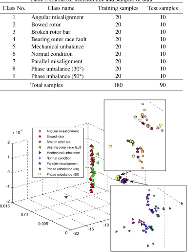
[image:5.595.140.459.441.639.2]Table 3 Classes of decision tree and samples of data
Class No. Class name Training samples Test samples
1 Angular misalignment 20 10
2 Bowed rotor 20 10
3 Broken rotor bar 20 10
4 Bearing outer race fault 20 10
5 Mechanical unbalance 20 10
6 Normal condition 20 10
7 Parallel misalignment 20 10
8 Phase unbalance (30°) 20 10
9 Phase unbalance (50°) 20 10
Total samples 180 90
Fig. 3 The feature of motor faults
[image:6.595.170.422.704.762.2]We have applied decision tree method as a classification model for fault diagnosis of induction motor with data gotten from vibration signals and current signals. In the testing data, 25% extra noise was inputted to test the accuracy of classification model. The result of classification is represented in Table 4.
Table 4 Fault classification using decision tree
Data Classification rate (%) Training Testing Vibration signals 100 98.89
Current signals 100 94.44
-20 -15
-10 -5
0 5
x 104 0
0.005 0.01
0.015 -2 -1 0 1 2
x 10-4 Angular misalignment
Conclusions
This paper has successfully described an application of decision tree for fault diagnosis of induction motors. The feature calculation was applied for the draw data beforehand to extract the useful information and then followed by decision tree. The results show that decision tree achieved high performance in classification of faults of induction motors. According to the result, the combination of decision tree and other methods aims to improve the accuracy of classification is considerable problem.
References
[1] B.S Yang, K.J. Kim (2006), Application of Dampster-Shafer theory in fault diagnosis of induction motors using vibration and current signals, Mechanical Systems and Signal Processing, 20, 403-420.
[2] G.G. Acosta, C.J. Verucchi, E.R.Gelso (2006), A current monitoring system for diagnosing electrical failures of induction motors, Mechanical Systems and Signal Processing, 20, 953-965. [3] B. Satish, N.D.R. Samar (2005), A fuzzy approach for diagnosis and prognosis of bearing faults
in induction motors, IEEE Power Eng. Society General meeting, 3, 2291-2294.
[4] B.S. Yang, S.K. Jeong, Y.M. Oh, A.C.C. Tan (2004), Case-based reasoning with Petri nets for induction motors fault diagnosis, Expert Systems with Applications, 27, 301-311.
[5] R. Casimir, E. Boutleux, G. Clerc, A. Yahoui (2006), The use of feature selection and nearest neighbors rule for faults diagnosis in induction motors, Engineering Applications of Artificial Intelligence, 19, 169-177.
[6] A. Widodo, B.S. Yang, T. Han (2006), Combination of independent component analysis and support vector machines for intelligent faults diagnosis of induction motors, Expert Systems with Applications, (in press)
[7] M.E.H. Benbouzid, H. Nejjari (2001), A simple fuzzy logic approach for induction motors stator condition monitoring, IEEE IEMDC2001, 634-639.
[8] B.S. Yang, C.H. Park, H.J. Kim (2000), An efficient method of vibration diagnosis for rotating machinery using a decision tree, International Journal of Rotating Machinery, 6(1), 19-27. [9] B.S. Yang, D.S. Lim, A.C.C. Tan (2005), VIBEX: An expert system for vibration fault
diagnosis of rotating machinery using decision tree and decision table, Expert Systems with Applications, 28, 735-742.
[10] M. Togami, N. Abe, T. Kitahashi, H. Ogawa (1995), On the application a machine learning technique to fault diagnosis of power distribution lines, IEEE Trans. on Power Delivery, 10(4), 1927-1936.
[11] T.M. Mitchell (1997), Machine Learning, Chap. 3, McGraw-Hill.