© 2016, IRJET | Impact Factor value: 4.45 | ISO 9001:2008 Certified Journal | Page 420
Comparison of Different types of Compensating Devices in Power
System
Arun Pundir
1, Gagan Deep Yadav
21
Mtech Scholar, YIET Gadhauli, India
2
Assistant Professor, YIET, Gadhauli, India
---***---Abstract - The quality of electrical power in a network is
a major concern which has to be examined with caution in order to achieve a reliable electrical power system network. Reactive power compensation is a means for realizing the goal of a qualitative and reliable electrical power system. This paper made a comparative review of reactive power compensation technologies; the devices reviewed include Synchronous Condenser, Static VAR Compensator (SVC) and Static Synchronous Compensator (STATCOM). These technologies were defined, critically examined and compared, the most promising technology is recommended for the realization of an effective, efficient, sustainable, qualitative and reliable electrical power network
Key Words: Reactive power compensation; synchronous
condenser; static VAR compensator; static synchronous compensator; reactive power compensation technology
1.
INTRODUCTION
There is a heightening concern in power efficiency and energy savings among policy makers, economics and academics from the aspect of technology, economic, policy and human behaviour point of view. Thus, the needs to further promote and explore energy efficient, reliable and sustainable technology such as synchronous condenser for reactive power compensation in electrical power systems [1]. Reactive power (Q) is an expression used for the unreal power from inductive loads like motor or capacitive loads, which normally is not so much common. It is widely calculated in units of VARs, that is volt-amps reactive. In order to maintain the most advantageous circumstances for a power system from engineering and economical point of view, it is very important to always apply the most advantageous reactive power compensation technology in an electrical power system [2], [3]. Reactive power compensation is defined as the administration of reactive power to ameliorate the production of Alternating Current (AC) in an electrical network. The idea of reactive power compensation encompasses an extensive and divergent field of both system and consumers problems, mostly connected with power quality matters, since most power quality issues can be resolved with appropriate control of reactive power [4]. The basic function of any electric power system is to convey electricity reliably and at a well synchronized frequency and voltage. Reliable and efficient Power Systems
WECS is one of the most attractive options among all the RES Reactive power compensation is an effective technique to enhance the electric power network, there is need for regulated reactive power compensation which can be done either with synchronous condensers, Static VAR Compensators (SVCs) or Static Synchronous Compensators (STATCOM) [1], [4], [5].
There are different technologies for reactive power compensation, these includes; Capacitor Bank, Series Compensator, Shunt Reactor, Static VAR Compensator (SVC), Static Synchronous Compensator (STATCOM), and Synchronous Condenser. But for the purpose of this paper, three different reactive power technologies are reviewed as possible sources for reactive power compensation. The technologies investigated includes; Synchronous Condenser, Static VAR Compensator (SVC) and Static Synchronous Compensator (STATCOM). The most promising technology is recommended for reactive power compensation in electrical power networks.
2. SYNCHRONOUS CONDENSERS
A. Definition and Overview© 2016, IRJET | Impact Factor value: 4.45 | ISO 9001:2008 Certified Journal | Page 421
systems beginning in the late 1920’s to the end of late 1970’s. Synchronous condensers have been relevant in the scheme of things in voltage and reactive power control for more than 50 years. Practically, a synchronous condenser is merely a synchronous machine linked to the power system. After the unit is synchronized, the field current is regulated to either generate or draw-up reactive power as needed by AC power systems. The device can provide incessant reactive power control when used with the right automatic exciter circuit. Synchronous condensers have been used at both distributions and transmission voltage levels to ameliorate stability and to support voltages within preferred boundaries under varying load states and emergency circumstances [4], [8]. However, synchronous condensers are infrequently used today because they need considerable foundations and a significant quantity of starting and protective gadgets. They also represent a part in short-circuit current, and they cannot be adjusted fast enough to balance speedy load changes. Furthermore, their losses are much higher than those related with static compensators, and the cost is much higher when likened with static compensators. Their merit lies in their high temporary over-load ability [4]. Synchronous condensers provide sustenance for network voltage by maintaining efficient and reliable operation of electrical power grids through reactive power compensation and extra short circuit power ability [9]. Synchronous condensers are well accepted technology for supplying reactive power and remedying power factor issues in industrial settings. Reliable Power Systems Synchronous Condensers are precisely designed to meet the requirements of hybrid renewable power systems. When compared with diesel generators, they help the diesels in controlling voltage. In high wind and/or solar times, the diesel generators are turned off, and the Synchronous Condenser handles voltage regulation on its own [10]. Synchronous condenser solutions are being initiated worldwide to play a part in the optimal use of energy resources and offer grid support for now and the future, in order to attain a reliable, secure, efficient, effective and sustainable electrical power supply [11]. The synchronous condenser capacity is depicted in figure 1.
B. Types of Synchronous Condensers
Conventional/Traditional Synchronous Condenser: This is a synchronous motor without any mechanical load. Its field is regulated by a voltage regulator to give rise to or to draw-up reactive power to sdraw-upport an electrical power system voltage or to keep a systems power factor at a specified level. Synchronous condensers installation and operation are identical to big electric motors. After the unit is synchronized, the field current is regulated either to give rise to or to draw-up reactive power as needed by AC system. The machine can supply uninterrupted reactive power regulation when used with the appropriate automatic exciter. A rise in the equipments field excitation brings about the provision of magnetizing power (kVArs) to an electrical power system. Its major merit is the effortlessness in the
[image:2.595.311.573.418.532.2]regulation of the amount of correction. [5], [13]. A single-phase scheme with a synchronous condenser is shown in figure 2.
Fig. 1. Synchronous Condenser Reactive Power Capacity [12].
Fig. 2. Single phase diagram with a synchronous condenser connected to grid [13].
© 2016, IRJET | Impact Factor value: 4.45 | ISO 9001:2008 Certified Journal | Page 422
conventional/traditional machines in the course of transient system faults, whereas, transient and sub-transient reactances are much the same to those of traditional machines.
The lower synchronous reactance of the super VAR permits the operation of these machines at lower load angles than traditional machines [3], [14], [15].
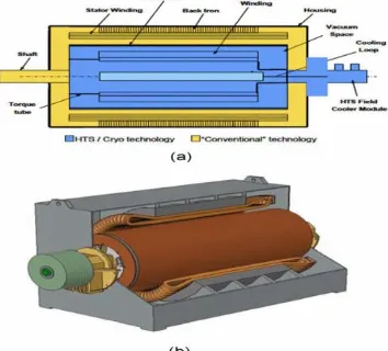
[image:3.595.73.250.386.546.2]Super VAR synchronous condensers act as reactive power shock-absorbers of an electrical power system grid, effectively producing or drawing-up reactive power (VARs), and base on the voltage level of a transmission system. Super VAR machines also react immediately to secure grids and electricity consumers in case of voltage sags and surges, which is recognized in the power industry as voltage transients, which can be given rise to by lightning storms, short circuits brought about by tree branches fleetingly touching lines, animals making contact with transmission elements, and other sources. Super VAR machines and Dynamic-VAR (D-VAR) systems immediately stabilizes voltage and supply utilities with economical techniques to actively improve the reliability and maximize the power of transmission grids [14]. The conceptual diagram of a Dynamic Synchronous Condenser (DSC) can be seen in figure3. (a) and (b).
Fig. 3. Conceptual diagram of a DSC [15]. (a) Superconducting field winding in cryocooler , (b) DSC model picture
3. STATIC VAR COMPENSATOR (SVC)
A. Definition and overviewA Static Var Compensator (SVC) is a thyristor-controlled (since it is thyristor controlled, thus it is called static) generator of reactive power, either lagging or leading, or both. This piece of equipment is also called a static reactive compensator. An SVC is a high voltage device that regulates effectively the network voltage at its coupling end. Its major function is to keep the network voltage constantly at a set reference point. Some other control characteristics of SVC are: voltage control, reactive power control, damping of power oscillations, and unbalance control. The design and configuration of an SVC device is all the time modified to the particular project specifications. An SVC is one of the regulators founded on Power Electronics and other static
devices known as Flexible Alternating Current Transmission Systems (FACTS) regulator, which is used to improve the ability and the flexibility of a transmission network. [16], [17], [18]. Static Var Compensator is a shunt-linked static VAR producer or assimilator whose output is regulated to exchange capacitive or inductive current so as to keep in good condition or regulate specific parameters of an electrical power system, typically bus voltage. SVC is founded on thyristors without gate turn-off ability. The operating concept and features of thyristors achieved variable reactive impedance SVC includes two main parts and their fusion: Thyristor-controlled Reactor (TCR) and Thyristor-switched Reactor (TSR); and Thyristor switched capacitor. The objectives of SVC design are reactive and load imbalance compensation, and with the use of traditional quantities in its regulator, it may be utilized in collaborative compensation methods for smart grids [19], [20].
B. Types of Static Var Compensator (SVC)
Thyristor-controlled Reactor (TCR): TCR is defined as a shunt-linked thyristor-controlled inductor whose effective reactance is regulated in a continuous manner by partial conduction regulation of the thyristor valve. A thyristor controlled reactor (TCR) is one of the traditional SVC used in the field of power quality enhancement. With the TCR type of SVC put together with fixed capacitors, when operating the system with a small reactive power, almost 100% reactive power is produced at the reactor unit and the general system reactive power is decreased. It can draw-up sustained reactive power at the primary frequency of the power system network, but it delivers appreciable odd harmonics which could cause many unpleasant consequences, such as; over currents, extra losses, and noises to telecommunication systems [18], [21], [22]. One-line diagram to compensate reactive power and voltage flicker enhancement in power system comprising Electric Arc Furnace (EAF) with a thyristor regulated reactor compensation, and fixed capacitor (TCR/FC) is shown in figure 4. [23]. TCR is also illustrated in figure 5 and 6. [19].
Fig. 4. Configuration of a TCR/FC connected to an EAF [23].
[image:3.595.310.577.580.721.2]© 2016, IRJET | Impact Factor value: 4.45 | ISO 9001:2008 Certified Journal | Page 423
[image:4.595.342.525.228.421.2]reactance is differed in a stepwise appearance by full conduction or zero-conduction management of the thyristor valve. Thyristor Switched Reactors are shunt compensators that can draw-up reactive power. The TSRs operating principle is simple; it has a delay of one half cycles and does not generate harmonics. The most general design of an SVC is made-up of a fixed shunt capacitor (FC) and a TCR. Filters are conventionally used to draw-up harmonic produced by SVC design and large industrial loads [24], [25]. A typical TSR can be seen in figure 5. [19].
Fig. 5. Static VAR Compensators (SVC): TCR/TSR, TSC, FC and Mechanically Switched Resistor [19].
Thyristor-Switched Capacitor (TSC): TSC is defined as a shunt-linked, thyristor-switched capacitor whose effective reactance is differed in a stepwise way by full-conduction or zero-conduction operation of the thyristor valve. It has similar composition and same operational mode as TSR, but the reactor is substituted by a capacitor. The reactance can only be either fully connected or fully disconnected zero due to the features of capacitor [24], [26]. The reactive power of a TSC is modified in steps decided by the number of banks of the capacitor. [21]. A typical TSC is illustrated in figure 5 and 6. Thyristor-Controlled Reactor and Thyristor-Switched Reactor (TCR/TSR) Combined: TCR and TSR are both made up of a shunt-linked reactor regulated by two parallel, reverse controlled thyristors. TCR is regulated with thorough firing angle input to function in a continuous way, while TSR is regulated without firing angle control which brings about a step change in reactance. TSC has the same make-up and same operational mode as TSR, but the reactor is substituted by a capacitor. The reactance can only be either fully connected or fully disconnected zero due to the features of capacitor. With non-identical combinations of TCR/TSR, TSC and fixed capacitors, an SVC can meet various requirements to draw-up or produce reactive power from or to the transmission line, The TSR system provides stepped variation of current and TCR provides consistent variation of current [19], [21], [26], [27]. To make-up for the limitations of the TSC, variable reactors are linked in parallel so that the general network reactive power can be fine-tuned continuously. The combined type has the merits of both the TCR and TSC, it is normally suited to a capacitor in a
substation for power system transmission lines, which must regulate reactive power for both the leading and lagging phases, usually it is standing by at zero (0) VAR state, and must modify reactive power speedily when a fault happens on the line. Appropriate Static Var Compensator (SVC) technology combinations are normally selected base on several factors such as the responsibility, minimum adjustment width, operating efficiency and economy. The diagram of an SVC combined technology is shown in figure 5 and 6. [19], [21].
Fig. 6. Structure of SVC Device, TCR and TSC Combined (a)TCR and (b) TSC [28]
4. STATIC SYNCHRONOUS COMPENSATOR
(STATCOM)
Static synchronous compensators (STATCOMs) are part of FACTS device lineage. Their primary aim is to provide a fast acting, precise, and adjustable quantity of reactive power to an AC power system network to which they are linked. STATCOMs accomplish this by modifying the magnitude and polarity (phase) of the reactive constituent of the current flowing into and out-of their AC side. This allows STATCOMs to regulate the quantity and direction of movement of the reactive power swapped with the AC power systems. They are frequently applied for dynamic power factor correction, such as dynamic reactive power compensation, in industrial machinery working with large arbitrary peaks of reactive power needed.
[image:4.595.37.273.228.373.2]© 2016, IRJET | Impact Factor value: 4.45 | ISO 9001:2008 Certified Journal | Page 424
5. TECHNOLOGY COMPARISON AND SELECTION
Here, three technologies have been examined, selection of the preferred technology will be made base on the following yardsticks; Control Coordination, Harmonics, Low-Voltage Ride-Through, Maintainability, Availability of Spare-parts, and Overload Duty-Cycle [5], [8], [31], [32].
Control Coordination: Examining the three technologies, both SVC and STATCOM applications stands for a notable risk of control coordination, making control coordination a challenge in SVC and STATCOM devices. And a plus for synchronous condensers compared to the other two technologies. Harmonics: Both SVC and STATCOM technologies have the potential to produce harmonics, while the synchronous condenser does not. In addition to not producing harmonics, a synchronous condenser can act as a sink for harmonics in a network were harmonics do occur. This attribute benefits the synchronous condenser.
Low-Voltage Ride-Through: Looking at low-voltage ride through, the SVC performance is less appealing than synchronous condenser or STATCOM. Synchronous condensers are a long-standing answer as reactive power sources that can and do ride-through low-voltage situations. Maintainability: One of the demerits normally connected with synchronous condensers is maintainability due to friction and wear. Static devices do require maintenance of auxiliary cooling systems, valve replacements, and control system upgrades. They also need special training of maintenance personnel who may not be used to working on such devices. Assessing the three technologies, the anticipated maintenance and up-keep costs for synchronous condenser technologies, and that of static technologies are even. In some situation, synchronous condenser maintenance may be simpler than that of an SVC and a STATCOM. Thus, there is no defined advantage in maintenance as regard the technologies reviewed.
Availability of Spare-Parts: One of the difficulties connected with maintaining older equipment has to do with capability to obtain needed spare parts. Advancements in technology are normally regarded as positive in terms of cost, performance or both. On the other hand, old technology is occasionally regarded as obsolete or ineffective, when in fact it may not be. Considering availability of spare-parts; particularly beyond twenty to thirty year window, there is greater certainty of parts and support for synchronous condenser-based reactive power device.
Overload Duty-Cycle: The synchronous condenser is well suited to manage overload duty. Depending on the design of the machine, and ceiling of the excitation system, the occasional overload rating of a synchronous condenser can be twice nameplate or more, for several seconds. This type of duty-cycle favors the synchronous condenser over SVC and STATCOM technologies.
6. CONCLUSION
[image:5.595.310.562.270.464.2]All three technologies are capable of supporting power system networks. Using the criteria’s listed above, this review suggest that the synchronous condenser technology is the most adequate and the best solution for reactive power correction in power system network. It is the most effective device to improve power systems performance; it helps to increase reliability and the quality of power delivery in a network. Synchronous condensers will be used on a much wider scale in the future as grid performance and reliability becomes an issue of more importance to policy makers, economics and academics, since having better grid controllability will allow utilities to reduce investment, most
Fig. 7. STATCOM installed in a Single Machine Infinite Bus (SMIB) system.[30].
especially on a long-term basis. Further research should be on comparing experimental and simulation results for the three reactive power compensation technologies on a grid setup and the authors are planning to do further studies in this area of concern.
REFERENCES
[1] Sumper, and A Baggini, “Electrical Energy Efficiency Technologies and Application,” John Wiley and Sons, West Sussex, United Kingdom, ISBN: 9780470975510, April 2012.
[2] Continental Control Systems, Reactive Power, “Continental Control Systems,” Boulder CO, USA, 2012. [Online]. Available from: http://www.ccontrolsys.com [3] NCT-TECH, “Power Factor Improvement,” Principles of Power System, pp. 101-126. [Online]. Available from: http://www.ncttech.edu.
© 2016, IRJET | Impact Factor value: 4.45 | ISO 9001:2008 Certified Journal | Page 425
[5] S. Teleke, T. Abdulahovic, T. Thiringer, and J. Svensson, “Dynamic Performance Comparison of Synchronous Condenser and SVC,” IEEE Transactions on Power Delivery, Vol. 23, no. 3, pp. 1606-1612, Jun. 2008. [6] C. Corvin, “ Slac Synchronous Condenser,” Stanford
Linear Accelerator Center, Sanford University, Stanford, CA 94309 USA. [Online]. Available from: http://epaper.kek.jp
[7] Abbreviations.com. "SYNCHRONOUS CONDENSER." STANDS4 LLC, 2015. Web. 18 Jan. 2015. [Online]. Available from: http://www.abbreviations.com [8] P. Marken, M. Henderson, D. LaForest, J. Skliutas, J.
Roedel, and T. Campbell, “ Selection of Synchronous Condenser Technology for the Granite Substation,” New Orleans, LA, USA, ISBN: 978-1-4244-6546- 0, IEEE, Apr. 2010.
[9] ABB, The Technical Synchrounous Condensers for Voltage Support in AC Systems. [Online]. Available from: http://www05.abb.com.
[10] Products Sustainable Power Systems, Boulder CO,
USA. [Online]. Available from:
http://www.sustainablepowersystems.com
[11] Siemens, “Synchronous Condensers,” [Online]. Available from: http://www.energy.siemens.com [12] J. M. Fogarty, and R. M. LeClair, “ Converting Existing
Synchronous Generators into Synchronous Condensers,” Power Engineering, volume- 115, issue-10 Oct. 2011. [Online]. Available from: http://www.powereng.com [13] T. Abdulahovic, S. Teleke, “Modelling and
Comparison of Synchronous Condenser and SVC,” Chalmers University of Technology, Göteborg, Sweden, 2006.
[14] American Superconductor Corporation, “American Superconductor's SuperVAR(TM) Synchronous Condenser Successfully Generates Reactive Power on Ohio Transmission Grid,” [Online]. Available from: http://www.prnewswire.com
[15] Geun-Joon Lee, “Superconductivity Application in Power System,”
“Applications of High-Tc Superconductivity,” Edited by; Adir Moysés Luiz, “ ISBN 978-953-307-308-8, Jun. 2011. [16] McGraw-Hill Concise Encyclopedia of Engineering. S.v.
"static var compensator." [Online]. Available from: http://encyclopedia2.thefreedictionary.com
[17] Siemens, “Static Var Compensator (SVC “Classic”),
[Online]. Available from:
http://www.energy.siemens.com
[18] R. Alves, M. Montilla, and E. Mora, "Increase of voltage stability and power limits using a static var compenstor". Universidad Simón BolívarCaracas, Venezuela, and Universidad de Los Andes-Mérida, Venezuela. [Online]. Available from: http://www.icrepq.com
[19] E. Csanyi, “ What is the Static Var Compensator (SVC),” Electrical Engineering Portal (EEP), Sep. 2011. [Online]. Available from: http://electrical-engineering-portal.com
[20] E. V. Liberado, W. A. Souza, J. A. Pomilio, H. K. M. Paredes, F. P. Marafão, “ Design of Static VAr Compensator using a General Reactive Energy Definition,” XI International School on Nonsinusoidal Currents and Compensation (ISNCC), Zielona Gora, Poland, ISBN: 978-1-4673- 6312-9 Jun. 2013,
[21] T. Hara, O. Motoyoshi, S. Konishi, K. Mukaimumine, Y. Yanagiya, K. Ishida, “ Components for Static Var Compensator,” Fuji Electric Review, Vol.29, no. 4, 1983, pp. 135-142, UDC 621.316.761.2 [Online]. Available from: http://www.fujielectric.com
[22] A. M. Obais, and J. Pasupuleti, “Harmonics Reduction of Thyristor Controlled Reactor with Minimal No Load Operating Losses,” Canadian Journal on Electrical and Electronics Engineering Vol. 2, No. 7, Jul. 2011. [23] R. A. Hooshmand, and M. T. Esfahani, “Optimal Design
of TCR/FC in Electric Arc Furnaces for Power Quality Improvement in Power Systems,” Leonardo Electronic Journal of Practices and Technologies pp. 31-50, Jul.-Dec. 2009.
[24] E. Acha, V.G. Agelidis, O. Anaya-Lara and T.J.E. Miller, “Power Electronic Control in Electrical Systems,” Elsevier Ltd, ISBN: 978-0- 7506-5126-4, pp. 178-188, 2002,
[25] A. Gelen, and T. Yalcinoz, “The Behaviour of TSR-Based SVC and TCR-Based SVC Installed in an Infinite bus System,” 25th Convention of Electrical and Electronics Engineers in Israel, IEEE, E-ISBN: 978-1- 4244-2482-5, pp. 120-124, Dec. 2008.
[26] S. Mahapatra, A. Goyal, N. Kapil, “Thyristor Controlled Reactor for Power Factor Improvement,” International Journal of Engineering Research and Applications,” ISSN : 2248-9622, Vol. 4, Issue 4 (Version pp.55-59, April 2014, [Online]. Available from: www.ijera.com [27] T. Vijayakumar, A. Nirmalkumar, and N. S.
Sakthivelmurugan, “Reactive Power Control Using FC -TSR – TCR,” Research Journal of Applied Sciences, Engineering and Technology 2(1): 1-4, ISSN: 2040- 7467. 2010.
[28] M. Zellagui, A. Chaghi, “Effects of Shunt FACTS Devices on MHO Distance Protection Setting in 400 kV Transmission Line, “ Scientific and Academic Publishing, Electrical and Electronic Engineering, pISSN: 2162-9455, e-ISSN: 2162-8459, 2012; 2(3): pp. 164-169, [Online]. Available from: http://article.sapub.org
[29] Festo Didactic, Static Synchronous Compensator (STATCOM), Electricity and New Energy, Courseware Sample, Festo Didactic Ltée/Ltd, Quebec, Canada, ISBN 978-2-89640-572-5, 2012.
© 2016, IRJET | Impact Factor value: 4.45 | ISO 9001:2008 Certified Journal | Page 426
[31] J. Skliutas, D. LaForest, R. D’Aquila, D. Derr, E. Kronbeck, “NextGeneration Synchronous Condenser Installation at the VELCO GraniteSubstation,” IEEE PES General Meeting, Calgary, Alberta, Canada, Jul. 2009. [32] N. Hingorani and L. Gyugyi, “Understanding FACTS,”
![Fig. 1. Synchronous Condenser Reactive Power Capacity [12].](https://thumb-us.123doks.com/thumbv2/123dok_us/8181774.810918/2.595.311.573.418.532/fig-synchronous-condenser-reactive-power-capacity.webp)
![Fig. 6. Structure of SVC Device, TCR and TSC Combined (a)TCR and (b) TSC [28]](https://thumb-us.123doks.com/thumbv2/123dok_us/8181774.810918/4.595.342.525.228.421/fig-structure-svc-device-tcr-tsc-combined-tcr.webp)
![Fig. 7. STATCOM installed in a Single Machine Infinite Bus (SMIB) system.[30].](https://thumb-us.123doks.com/thumbv2/123dok_us/8181774.810918/5.595.310.562.270.464/fig-statcom-installed-single-machine-infinite-smib-system.webp)
