http://dx.doi.org/10.4236/eng.2015.71003
How to cite this paper: Salehi, M.A. and Basiry, A. (2015) Dynamic Simulation of Volume Fraction and Density Solid Phase Effect on Phase Hold-Up in 3 Phase Fluidize Bed Column through CFD. Engineering, 7, 31-35.
http://dx.doi.org/10.4236/eng.2015.7103
Dynamic Simulation of Volume Fraction and
Density Solid Phase Effect on Phase Hold-Up
in 3 Phase Fluidize Bed Column through CFD
Mohammad Ali Salehi
*, Ali Basiry
Department of Chemical Engineering, University of Guilan, Rasht, Iran Email: *[email protected]
Received 28 December 2014; accepted 13 January 2015; published 21 January 2015
Copyright © 2015 by authors and Scientific Research Publishing Inc.
This work is licensed under the Creative Commons Attribution International License (CC BY).
http://creativecommons.org/licenses/by/4.0/
Abstract
The gas-liquid-solid fluidized bed has emerged in recent years as one of the most promising de-vices for three-phase operation. Selection and design is one of them in parameter in the perfor-mance of three phase system. This paper focuses on volume fraction and density effect on the phases hold-up in a 3 phase fluidize bed column containing liquid phase with 100 cm height and 20 cm diameter, in this case the solid phase with 0.15, 0.25, 0.35 volume fraction and density 2470, 3000, 4000, 5000 m3 dispersion into liquid phase and the gas phase enter the column through a
sparger of 2 cm diameter with 0.02 m/s velocities. The results show as the solid phase volume fraction increases from 0.02 to 0.08 m/s. The gas hold-up decreases and solid hold-up increases. Solid phase density increases, so solid phase hold-up decreases and gas hold-up decreases.
Keywords
Hydrodynamic Fluidized Bed, Phases Hold-Up, Three Phase Fluidized Bed Column CFD
1. Introduction
The gas-liquid-solid fluidize bed has in emerged recent years as one of the most promising devices for three phase operation. Such a device is of considerable industrial importance as evident from its wide application in chemical, petrochemical and biochemical processing [1]. In this type of reactor, gas and liquid are passed through a granular solid material at high enough velocities to suspend the solid in fluidized state. The solid par-ticles in the fluidized bed are typically supported by porous plate known as distributor at the static condition.
The fluid is then forced through the distributor up through the solid materials at lower fluid velocities, the solid remain in place as the fluid passes through the voids in the material. As the fluid velocity is increased, the bed reaches a stage where the force of the fluid on the solids is enough to balance the weight of the solid material. This stage is known as incipient fluidization and the corresponding fluid velocity is called the minimum fluidi-zation velocity. In fluidized bed reactors, the density of are much higher than the density of the liquid and par-ticles size is normally large (above 150 µm) and volume fraction of parpar-ticles varies from 0.6 (packed stage) to 0.2 as close to dilute transport stage (Paneerselvam et al. 2009) [2]-[11].
Even though a large number of experimental studies have been directed towards the quantification of flow structure and flow regime identification for different parameters and physical properties, the complex hydrody-namics of these reactors are not well understood due to the interaction of all the three phases simultaneously. It has been a very tedious task to analyze the hydrodynamic property experimental way of three phase fluidized bed reactor, so another advanced modeling approaches based on CFD techniques have been applied for investi-gation of three phases for accurate design and scale up. Basically, two approaches, namely the Euler-Euler for-mulation is based on the interpenetrating multi fluid model. And the Euler-Lagrangian approaches based on solving Newton Equation motion for dispersed phase are used.
Bahary et al. (1994) have used Eulerian multi-fluid approach for three phase fluidized bed [2] [3], where gas phase are treated as a particulate phase having 4 mm diameter and a kinetic theory granular flow model is ap-plied for solid phase. They have simulated both symmetric and axisymmetric model and verified the different model regimes in the fluidized bed by comparing with experimental data.
Schallenberg et al. (2005) have used 3-D multi-fluid Eulerian approach for three phase bubble column. Gas- liquid drag coefficient based on single bubble rise modified for the effect of solid phase [4]. Extended K-ε tur-bulence model to account for bubble-induced turtur-bulence has been used and the interphase momentum between two dispersed phases include. Local gas and solid hold-up as well as liquid velocities have been validated with experimental data.
Panneerselvam et al. (2009) have work in 3-D Elerian multi-fluid approach for gas-liquid-solid fluidized bed [5]. Kinetic theory granular flow (KTGF) model for describing the particulate phase and a K-ε based turbulence model for liquid phase turbulence have been used. The interphase momentum between tow dispersed phases has been included. Radial distributions of axial and radial solid velocities, axial and radial solid turbulent velocities, shear stress axial bubble velocity, axial liquid velocity and average gas hold-up and various energy flows have been studied. In the present work configuration of cylindrical column has been taken for studying co-current gas- liquid-solid fluidization with the help of commercial CFD codes as FLUENT 6.2. The main focus for analyzing the results is on the column with 1 m height and diameter of 0.2 m containing solid particles as glass beads with 0.15 volume fraction dispersion into liquid phase and the gas phase entered the column through a sparger of 2 cm diameter with various velocities. In the present study of three phase fluidized simulation, the hydrodynamic investigated includes phase hold up, solid phase effect and velocity profiles of all phases.
2. Theory and Hydrodynamics
Hydrodynamic equations used in this research are based on the following equations:
2.1. Base Model Equation
In the Equation (1) which is continuity equation, ρk density and εk as volume fraction of gas, liquid and solid
phases. Thus the sum of volume fraction of three phases presents εl+εv+εg =1 in the equation of (2), namely momentum equation, the phases volume fraction rα are correlated to interphase movement Mαi for Np in Naviar
stock sequation. Hence, the right quotations of the Equation (2) describe those operating forces on fluidized element of phase X into the control volume. The total pressure gradient, the viscosity tensions, the gravity forces and interphase momentum forces have been mixed in Mαi. The Equation (3) expresses the drag force among liq-uid and gas phases which has different amounts in different Reynolds. The Equation (4) shows the drag force among solid and gas phases that is known as Gidaspaow [12] [13].
)
(
k k(
)
k k k
t
ε ρ
ρ ε µ
∂
+ ∇
)
(
a a a i(
a a a j)
ai aia a a a i ai
j i
r u
r u p u u
r r r g M
t t x x x x
ρ
ρ
µ
ρ
⋅ ⋅ ∂ ∂ + = − ∂ + ∂ ∂ +∂ + + ∂ ∂ ∂ ∂ ∂ ∂ (2)
2
18
i
i di
µ τ
µ
= (3)
)
(
1 1 1 12 1
1
150 s 1.75 s s
sl
s s
a v v
a a k d a d ρ µ − −
= + (4)
2.2. Multiphase Models
This research has employed the multiphase model Eulerian. The model considers the phases as come turbulence environments in with the possibility of each phase existing in calculating. Range will be determined by its volume fraction and sum of the volume fractions is equal to unity. The interphase momentum appears as a drag which is a function of stumbling velocity between yhe phases. In this research, liquid acts as a continual phase and gas acts as a diffuse phase which get into the system from the bottom of column.
2.3. Model and the Wall Boundary Condition
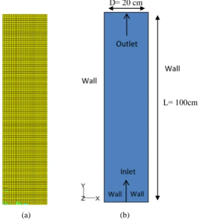
Boundary conditions on the wall occur as the boundary condition of inlet at the sparger, the boundary condition of outlet pressure at the top of column as well as the wall boundary condition at the walls. The model consists of a cylinder 20 cm in diameter and 100 cm in height. The gas flow lets in the bottom of column , passing through the static liquid and also the solid phase dispersed inside the liquid phase with 0.15 volume fraction, then lets out of the top. Air crosses over the fluidized column with various velocity. The research applies two dimensional simulations under condition of axis symmetry and inlet dry air.
3. Geometry and Mesh
[image:3.595.169.528.82.197.2] [image:3.595.215.412.486.703.2]The first step in CFD simulation of fluidized bed column is preprocessor, which has been done by GAMBIT tools, to design the problem in geometrical configuration and mesh the geometry. Before fluid flow problems can be solved, FLUENT needs the domain in which the flow takes place to evaluate the solution. The flow do-mains as well as the grid generation in to the specific domain have been created in GAMBIT which is shown in
Figure 1.
(a) (b)
(a) (b)
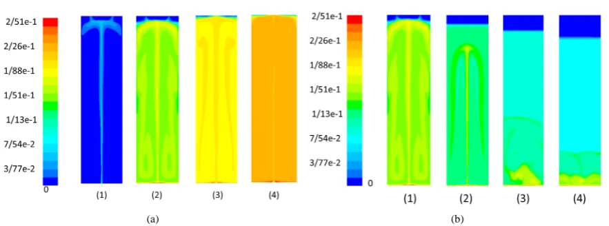
Figure 2. (a) Solid volume fraction changes in a column of 100 cm height and 20 cm diameter. The inlet gas velocity of 2cm/s. The solid volume fraction increases of 0.15, 0.25, 0.35. (b) Effect of solid volume fraction changes in relation to solid density changes of 2470, 3000, 4000, 5000 kg/m3.
[image:4.595.95.535.290.440.2](a) (b)
Figure 3. (a) Effect of the solid volume fraction increase on the solid hold-up. (b) Effect of solid volume fraction on the gas hold-up.
4. Discussion and Conclusions
Figure 1 shows the bubble column containing the liquid phase and the solid particles of volume fraction 0.15 at t = 0 s. Gas phase enters the column through a sparger 2 cm diameter with velocity of 2 cm/s. As the determined times pass, the solid phase hold-up will decrease.
Figure 2(a) looks over the changes of the solid phase hold-up and of the solid phase volume fraction in the fluidized bed column. It shows that the increase in the solid phase volume fraction results in the increase of the solid phase hold-up.
Figure 2(b) demonstrates the effect of the solid phase volume fraction on the solid phase hold-up. The results represent when the solid phase volume fraction goes up, the gas phase hold-up goes down. Two graphs present the inverse effect of the volume fraction increase on the gas and solid phases hold-up.
Figure 3(a)studies the solid phase hold-up changes in relation to the solid phase density. The results express that the solid phase hold-up decreases as the solid phase density goes up to 2470, 3000, 4000, 5000 kg/m3.
Figure 3(b) shows that when the solid phase density increases, the gas phase hold-up goes down.
References
[1] Panneerselvam, R., Savithri, S. and Surender G.D. (2009) CFD Simulation of Hydrodynamics of Gas-Liquid-Solid Fluidized Bed Reactor. Chemical Engineering Science, 64, 1119-1135.
[3] Pain, C., Mansourzadeh, C. and Oliveira, S. (2001) A Study of Bubbling and Slugging Fluidized Beds Using Two Flow Granular Temperature Model. International Journal Multiphase Flow, 27, 527-551.
http://dx.doi.org/10.1016/S0301-9322(00)00035-5
[4] Schallenberg, J., Enb, J. and Hempel, D. (2005) The Important Role of Local Dispersed Phase Hold-Ups for the Cal- culation of Three Phase Bubble Columns. Chemical Engineering Science, 60, 6027-6037.
http://dx.doi.org/10.1016/j.ces.2005.02.017
[5] Savithri, S. and Surender, G.D. (2009) CFD Simulation of Hydrodynamics of Gas-Liquid Reactor. Chemical Engi- neering Journal, 31, 1024-1032.
[6] Kunii, D. and Levenspiel, O. (1991) Fluidization Engineering. 2nd Edition, Butterwo, Washington DC.
[7] Howard, J. (1989) Fluidized Bed Technology. Principles and Applications. Adam Higler, New York.
[8] Park, H. (2009) CFD Advantages and Practical Applications. Glumac Inc., Portland.
[9] Trambouze, P. and Uzen, J. (2004) Chemical Reactors, From Design to Operation. Technip, Paris.
[10] Muroyama, K. and Fan, L. (1985) Fundamentals of Gas-Liquid-Solid Fluidization. AIChE Journal, 31, 1-34.
[11] Epstein, N. (1981) Three-Phase Fluidization. The Canadian Journal of Chemical Engineering, 59, 649-757.
http://dx.doi.org/10.1002/cjce.5450590601
[12] Dudukovic, M.P., Larachi, M.P. and Mills, F. (1999) Multiphase Reactors-Revisited. Chemical Engineering Science,
54, 1975-1995. http://dx.doi.org/10.1016/S0009-2509(98)00367-4