© 2016, IRJET | Impact Factor value: 4.45 | ISO 9001:2008 Certified Journal
| Page 1057
Analysis and implementation of Reed
Salomon codes for Forward Error
Correction using LabVIEW
Satyanarayana Reddy K
Student,
Dept. of Telecommunication, R.V.College of Engineering, Bangalore, India
Neethu S Assistant Professor, Dept. of Telecommunication, R.V.College of Engineering, Bangalore, India
---***---
Abstract -In the current world, communication have got many applications such as telephonic conversations, Broadband and DTH etc., in these applications the messages are encoded and then transmitted over a communication channel. The receiver receives messages and then decoding back to original message. During this transfer of the message, message bits may get corrupted due to lots of disturbances like noise and ISI in the channel which the message is transferred. So it is necessary that, for a decoder to have the function of correcting errors that might occur. Reed Solomon codes are type of burst error detecting codes which has got many applications due to its burst error detection and correction nature. The main aim of the paper is to implement this Reed Solomon codes in LABVIEW and to analyse the error probability that occurs during transmission. To perform the check, one can start simulating Reed Solomon codes in LABVIEW tool.
INTRODUCTION
In recent past digital data and its transmission over either in wired or wireless channel with the minimum bandwidth requirement and high data rate is playing vital role in communication field. Source coding and channel coding are the two traditional sub modules in error control coding. Source coding deals with the coding of messages generated by the source by considering its probability of occurrence so as to maximize the flow of message in the channel. Waveform coding and structured sequences are the two most common channel coding methods. These two techniques are preferable only when the bandwidth available is large because the bandwidth required increases exponentially as the number of waveform generated is increases.
© 2016, IRJET | Impact Factor value: 4.45 | ISO 9001:2008 Certified Journal
| Page 1058
Fig. 1.1 Diagram showing encoding & decoding strategy in Error control coding [1]
In olden days the parity bits are used to check whether the message has been delivered properly or not. If not delivered without error then ARQ (automatic retransmission query) mechanism was used which causes inefficient bandwidth usage, delay in transmission and lower data rate. The key for achieving error free digital communication in the presence of distortion, noise and interference is the addition of redundant bits to the original data bits which leaded to the invention and evolution of forward error correction codes viz., block codes and convolutional codes. FEC provides an efficient way of data compression by ensuring compressed data through the process of adding redundancy bits.
II FORWARD ERROR CORRECTION
2.1 Need for Forward Error Correction
[image:2.595.194.403.488.624.2]The conventional method used for error detection and correction is Automatic Repeat Request in which receiver sends an acknowledgement on receiving sent bit stream correctly, if not on receiving negative acknowledgement from the receiver the transmitter has to resend data packets containing message bits over the channel. This is a tedious process and causes inefficient usage of bandwidth by sending the same data over the channel repeatedly. It is customary to encounter issues like low speed and memory management at both transmitter and receiver side in ARQ [2]. The power level required to transmit the bit stream or the packets and device requirements will increase the production cost of the devices. Due to all of these reasons the need of a mechanism which performs the automatic detection of a bit when a train of bits is transmitted and corrects error bits on its own without any re-acknowledgement or negative acknowledgement, was inevitable. Since resending of the transmitted bit stream is not needed in this technique hence the name FEC.
Fig. 2.1 FEC in standard wireless communication system [3]
© 2016, IRJET | Impact Factor value: 4.45 | ISO 9001:2008 Certified Journal
| Page 1059
The message bits to be transmitted is processed in such a way that additional bits are created and added to the original message. These extra bits help in the detection and correction of the message bits received at the receiver. The key point about channel coding is it takes more time to transmit compared to ARQ, due to the presence of extra bits and encoding mechanisms. As they consume more time for transmission they are known as overhead. Channel encoding involves both single and multiple, error detection and error correction codes.2.1.1 Classification of FEC codes
Applications of these Forward error correction techniques are very well utilized in the field of data transmission and storage systems. The evolution of the large scale, high speed data communication network for exchange, storage and processing of digital information in the fields like commercial, medical and military applications are few of the domains over which FEC can be applied. For all these requirements a digital system has to undergo a several crucial manufacturing cycles, and implementation processes among which major importance is given to the error control which is the responsibility of a system design engineer.
As long as capacity of the channel is more than the information rate there will be more chances of reducing the errors induced by the noisy channel or storage medium to a desired level. The developments that has taken place in the field of communication toward the achievement of faster data rates in modern communication and digital storage systems made the error control coding as an integral part of communication system and eradicated the implementation of ARQ in systems.
[image:3.595.173.408.351.490.2]Forward error correction codes are broadly classified as block codes and convolutional codes depending on whether they require memory for appending parity and redundant bits to a set of message sequence or not.
Fig. 2.2 Classification of FEC codes [5]
Block codes has no memory since it does not require memory elements to store the bits that it has to process and it collects and isolates them in a buffer prior to processing. It is said to be memoryless as there is no retention within the encoding system of information related to the previous sample points. Hence each code word for a (n, k) block code depends only on the present buffer. Fig. 1.4 shows the classification of forward error correction codes in the form of a tree structure.
In case of convolutional codes there can be more chance of encoding and processing large number of samples in a single cycle, therefore sample points collected prior to encoding is too less than required for block codes. Hence delay through encoder is far less as a result serial bit stream as it enters into the transmitter the encoder acts upon and manipulates the data.
2.2 Problem Statement
Analysis of RS codes for different channel conditions like BER and SNR considering PSK and higher levels of PSK like QPSK, 8-PSK and 16-8-PSK as a modulation technique voice as a modulating signal over an AWGN channel using LabVIEW.
III CHANNEL AND CODED MODULATION 3.1 Binary and Non binary codes
© 2016, IRJET | Impact Factor value: 4.45 | ISO 9001:2008 Certified Journal
| Page 1060
Non binary codes are highly used because their efficiency can be improved by increasing their error correcting and detecting capability. In binary codes like linear block codes, cyclic codes and hamming codes messages and generator polynomials are represented and processed with two binary representations ‘0’s and ‘1’s. The code words in case of non-binary system are generated and manipulated by defining an arbitrary constant called ‘α’. Non binary operations are performed based on the linear algebra of equations obtained by representing the generator vector, message vector and code vector in polynomial form [8].3.2 Modulation and Coding
[image:4.595.197.400.256.335.2]Waveforms of duration i.e., time period T that is suitable for transmission of each encoder symbol can be selected by the modulators in each communication system. A most common type of noise present in every communication system is Additive White Gaussian Noise (AWGN). Other forms of noises are also present in channel which can be modelled as a multiplicative scale factor on the signal. Processing of some unquantized demodulator outputs can be done by passing them through channel decoder.
Fig. 3.1 Modulation and coding scheme in QPSK [9]
A much more similar and simpler method of decoding is to quantize the output symbols into discrete levels. To transmit information with channel signals each output from binary encoder is segmented into a set of ‘0’s and ‘1’s called bytes. Each signal is mapped onto set of signals for transmission. A block diagram showing coding and modulation scheme implemented for QPSK is as shown in Fig. 1.5.
3.3 Coded Modulation
Expansion in channel bandwidth for signal transmission is the main drawback in combining coding with binary modulation techniques for achieving high coding gain. Comparatively more bandwidth is needed for un-coded information sequence than that is needed for coded information sequence. By adding redundant bits to the transmitted sequence effect of channel noise can be minimized. Coding of information sequences provides an effective trade-off between channel bandwidth and transmitter power and is also suitable for communication system that are designed to operate in power limited channels [10].
Common power limited application fields are deep space, satellite and other wideband communication systems. Bandwidth is a tight constraint for many applications like voice transmission, terrestrial microwave and some satellite channels. This is why coding by adding redundant bits is rarely used in band limited channels. This problem can be overcome by using coding techniques in conjunction with multilevel modulation techniques.
The basic idea of coded modulation is expanded modulation signal sets above which information symbols are encoded. The redundancy needed for the error control is provided by the same signal set without increasing the signaling rate and bandwidth. In power limited channels coding by adding additional redundant bits is more suitable for error control.
IV METHODOLOGY
For simulating RS code in LabVIEW many small VI blocks are used, some of them are explained below. It’s also important to know how to digitize the sound waves in LabVIEW.
4.1 Encoding and Decoding of RS codes
The normal Reed-Solomon (n,k,t) code consists of values of n of the form n = 2m–1, where valid values of m are 2 to 16,
© 2016, IRJET | Impact Factor value: 4.45 | ISO 9001:2008 Certified Journal
| Page 1061
.Fig. 4.1 VI block to Encode RS code (shortened).
The normal Reed-Solomon (n,k,t) code consists of values of n of the form n = 2m–1, where valid values of m are 2 to 16, inclusive.
For example, specify n=255, k = 233 to produce a Reed-Solomon (255,233,11) code. This code has an error-correcting capacity of 11 Reed-Solomon symbols. The block diagram of the same is as shown in Fig. 4.2.
Fig. 4.2. VI block to Decode RS code (Normal).
4.2 Packing and Unpacking bits
Packs data to an unsigned or signed integer array. You can specify the order in which the bits are packed into the integer array either as MSB first or LSB first, using the packs bits array parameter. You can also specify the integer format as Signed or
Unsigned using the integer format parameter. The block diagram of the same is as shown in Fig. 4.3. This VI packs MN-sized binary data of the form bi = {0,1}, to an unsigned or signed integer array a_n,
Fig. 4.3. VI block to PACK bits.
Unpacks data to an unsigned or signed integer array. You can specify the order in which the bits are unpacked into the integer array either as MSB first or LSB first, using the packs bits array parameter. You can also specify the integer format as Signed or
Unsigned using the integer format parameter. The block diagram of the same is as shown in Fig. 4.4.
Fig. 4.4. VI block to Unpack bits.
4.3 BER calculation
© 2016, IRJET | Impact Factor value: 4.45 | ISO 9001:2008 Certified Journal
| Page 1062
Fig. 4.5 VI block to calculate BER
4.4 Simulation of sound waves
4.4.1 Digitization of sound waveform
[image:6.595.205.399.285.387.2]The sound waveform recorded and plotted on a waveform generator will be next send to the logic encode block to convert it into a train of 0’s and 1’s. The block diagram of the encoding the continuous analog waveform into a digital stream is as shown in the fig. 4.6.
Fig. 4.6 Logic to convert continuous sound waveform to digital form
4.4.2 Logic for recovery of Sound waveform
In the process of applying error control techniques and modulation blocks the sound wave form in digital form will be stored
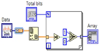
[image:6.595.196.401.512.585.2]in array for easy data manipulation and modification. Hence to recover the same sound waveform it is necessary to apply the same logic used in conversion of continuous sound waveform into digital in a reverse manner. The block diagram of the logic applied is as shown in the fig. 4.7.
Fig. 4.7 Logic to convert sound in digital array format into continuous form
V SIMULATION RESULTS AND CONCLUSION
5.1 Simulation Results
© 2016, IRJET | Impact Factor value: 4.45 | ISO 9001:2008 Certified Journal
| Page 1063
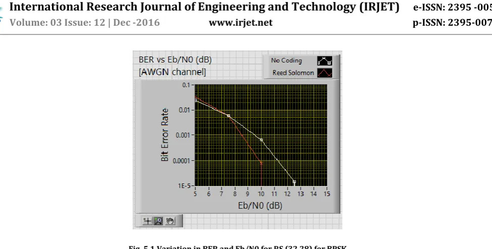
Fig. 5.1 Variation in BER and Eb/N0 for RS (32,28) for BPSK
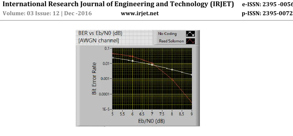
[image:7.595.193.402.374.552.2]Now the similar graphs for variation in Eb/N0 vs BER are plotted for RS specification (32,6) and results are shown in Fig.5.2. In the fig.5.2 the same input voice signals are checked for different length of message bits and the error correction capability of the RS codes. It is found that BER is high for coded bit stream than the un-coded bit stream. Later curve gradually decreases to lesser values at higher values.
Fig. 5.2 Variation in BER and Eb/N0 for RS (32,6) for 8PSK
© 2016, IRJET | Impact Factor value: 4.45 | ISO 9001:2008 Certified Journal
| Page 1064
Fig. 5.3 Variation in BER and Eb/N0 for RS (63,45) for BPSK
For most of the voice transmission RS of specification (63, 51) is used hence the results for RS specification (63,51) for
different levels of PSK are shown in Fig.5.4. As similar to the previous outputs the nature of the graph and all properties remains same for the RS specification of (63,51). The coding is increased by 2 to 3 dB with the increase in the number of correction bits and higher levels of PSK modulation.
The different coding gain for few of the RS length specifications and PSK levels can be tabulated as shown in the table 5.1.
RS Specific ation
SNR at zero BER for coded bit stream in dB
SNR at zero BER for non-coded bit stream in dB
Coding gain in dB
PSK
levels 2 4 8 2 4 8 2 4 8
32,28 10 10 15.4 12.5 11.6 18.5 2.5 1.6 3.1
32,6 11 12 16 13 12.5 20.2 2.1 0.5 4.2
63,45 9.3 8 12.5 12.5 11 15.5 3.2 3 3
63,51 8.5 8.8 13.2 12 13.1 16.5 3.5 3.3 3.5
Table 5.1 coding gain for different PSK modulation levels
From the table it can be found that coding gain is found to be increasing as the number of error correction bits is increased in the RS code. As the number of level in PSK modulation increases the null points of the respective curves shifts to the higher SNR values indicating that more energy per bit is required for the transmission of data bits. Lower PSK levels indicate lower probability of BER but with lesser coding gain as compared to that of higher PSK modulation levels. In all the results obtained it can be inferred that BER will be high for lesser SNR values and will be slightly lower for coded bit streams in case of increased error correcting bits.
5.2 Conclusion
[image:8.595.190.411.79.262.2]© 2016, IRJET | Impact Factor value: 4.45 | ISO 9001:2008 Certified Journal
| Page 1065
transmission over the channel gives poor performance with RS coding of specification (63,45) it is preferred more because of provision for trade-offs and possibility of achieving coding gain during transmission.VI REFERENCE
[1] M. Bystrom and J. W. Modestino, "Combined source channel coding schemes for video transmission over an additive white Gaussian noise channel," in IEEE Journal on Selected Areas in Communications, vol. 18, no. 6, pp. 880-890, June 2000. [2] Svilen Dimitrov, Balazs Matuz, Gianluigi Liva, Ricardo Barrios, Ramon MataCalvo and Dirk Giggenbach, “Digital Modulation and Coding for Satellite optical feeder links,” in the proceedings of IEEE conference on Advanced Satellite Multimedia Systems,
pp.150-157, 2014.
[3] Z. Liu and S. Jin, "An interaction between network coding and end-host coding," in the proceedings of IEEE Wireless
Communications and Networking Conference, pp. 885-890, 2011.
[4] J. Bas, F. Vázquez-Gallego, C. Gavrincea and J. Alonso-Zarate, "Energy and delay analysis of Binary RS codes for Machine-to-Machine networks with small data transmissions," in the proceedings of IEEE 24th Annual International Symposium and Mobile
Radio Communications (PIMRC), pp. 1873-1877, 2013.
[5] O. Ytrehus, "Upper bounds on error-correcting runlength-limited block codes," in IEEE Transactions on Information Theory, vol. 37, no. 3, pp. 941-945, May 1991.
[6] Yan Xin and I. J. Fair, "A new metric for comparing performance of high-order spectral-null codes," in the proceedings of
IEEE International Symposium on information theory, Washington, DC, pp. 252, 2001.
[7] J. Barros, R. A. Costa, D. Munaretto and J. Widmer, "Effective Delay Control in Online Network Coding," in the proceedings of
IEEE conference on network coding, INFOCOM Rio de Janeiro, , pp. 208-216, 2009.
[8] S. Sharifi Tehrani, S. Mannor and W. J. Gross, "Fully Parallel Stochastic LDPC Decoders," in IEEE Transactions on Signal
Processing, vol. 56, no. 11, pp. 5692-5703, Nov. 2008.
[9] M. I. Hayee and A. E. Willner, "NRZ versus RZ in 10-40-Gb/s dispersion-managed WDM transmission systems," in IEEE
Photonics Technology Letters, vol. 11, no. 8, pp. 991-993, Aug. 1999.
![Fig. 2.1 FEC in standard wireless communication system [3]](https://thumb-us.123doks.com/thumbv2/123dok_us/8180643.810664/2.595.194.403.488.624/fig-fec-standard-wireless-communication.webp)
![Fig. 2.2 Classification of FEC codes [5]](https://thumb-us.123doks.com/thumbv2/123dok_us/8180643.810664/3.595.173.408.351.490/fig-classification-of-fec-codes.webp)
![Fig. 3.1 Modulation and coding scheme in QPSK [9]](https://thumb-us.123doks.com/thumbv2/123dok_us/8180643.810664/4.595.197.400.256.335/fig-modulation-and-coding-scheme-in-qpsk.webp)