© 2017, IRJET | Impact Factor value: 5.181 | ISO 9001:2008 Certified Journal
| Page 1494
Modeling and Fuzzy Logic Control of a Quadrotor UAV
Muhammad Awais Sattar
1, Dr Abdulla Ismail
21
Graduate Student, Dept. of Electrical Engineering, Rochester Institute of Technology, Dubai, UAE
2
Professor, Dept. of Electrical Engineering, Rochester Institute of Technology, Dubai, UAE
---***---Abstract - Quadrotors have a variety of applications in realtime e.g. surveillance, inspection, search, rescue and reducing the human force in undesirable conditions. Quadrotor UAV is equipped with four rotors for the purpose of stability but this will make quadrotor more complex to model and control. In this paper, intelligent controller is designed to control attitude of quadrotor UAV. The paper presents a detailed simulation model for a Quadrotor UAV and Fuzzy logic control strategy is designed to implemented for four basic motions; roll, pitch, yaw, and Z Height. The controller presented in this paper is very simple in structure and it is easy to implement. The main objective of this paper is to get the desired output with respect to the desired input. Simulink model and results are shown at the end of the paper
Key Words: Quadrotor, UAV, Fuzzy logic Control, Dynamics, Roll, Pitch, Yaw
1. INTRODUCTION
A quadrotor or quadcopter can be defined as a “multi-rotor copter with four arms, each of which have a motor and a propeller at their ends” [1].
[image:1.595.340.520.534.627.2]UAVs are classified depending upon type of wings as shown in figure 1.
Figure -1: UAV Classification
Quadrotor lies in the category of Rotary wing class of UAVs they are usually used in the applications that required hovering flights such as search and rescue operations, security, journalism, emergency response and in military applications [2].
Quadrotors UAV are different from a helicopter for two main reasons
a) The way they are controlled i.e. helicopters are not fully autonomous
b) Second is helicopter can change their blades angle of attack while quadrotor lacks this functionality.
Quadrotors have many advantages over traditional helicopters such as
a) Quadrotors have Small sizes
b) They are safe to use for civilians because of small rotor.
c) Less complex mechanical structure d) They are very easy to maintain
e) Due to their maneuverability, they are safer in hazardous situations
This paper presents different classical and modern control strategies for the control of quadrotor. Simulations result and comparison of all control techniques are presented at the end of this paper.
2. Dynamic Modeling of Quadrotor
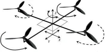
Quadrotor UAV flies with the assistance of four motors as shown in figure below. For the purpose of vertical flight two opposite motors rotates in the similar direction. The combination of opposite motors rotates in the similar direction for stabilization on the x-axis other combination of opposite motors keeps it stabilizes on the y-axis [3].
[image:1.595.46.281.537.613.2]
Figure -2: Quadrotor Motion
Quadrotor UAV is a 6 DOF aircraft, so there are 6 variables (x, y, z,∅,θ and φ) that are used to express its orientation in space. ∅, θ, and φ are also known as Euler’s angles. Details of each variable are as follows [4]
x and y: These variables are used to represent the position of Quadrotor in space.
© 2017, IRJET | Impact Factor value: 5.181 | ISO 9001:2008 Certified Journal
| Page 1495
ϕ: ϕ or Roll angle it represent angle about thex-axis
θ : θ or Pitch angle it represent angle about the y-axis
φ : φ or Yaw angle it represent angle about the z-axis
In this Paper, Newton-Euler formalism is used to derive the dynamics of the quadrotor. Following are the assumptions made for the design [5]
The Structure is rigid and symmetrical The propellers are rigid
Thrust and drag are proportional to square of propellers speed
The model presented in this Paper is considering following equation of motion
(1)
In equation (1) m [kg] represent the mass of quadrotor helicopter whereas Ixx [Nms2], Iyy-[Nms2], Izz [Nms2] describes the factors of inertia matrix expressed in body system, J [Nms-1] is the angular momentum and Ω [rads-1] is the speed of propeller. U1, U2, U3, U4 are the inputs or translation vector factors. Basic motions and the speed of the propeller can be depicted by following equation 2 [6]
(2)
In equation (2) l[m], b[Ns2] and d[Nms2] describe the distance between propeller center and quadrotors center, lift and drag respectively. Ω1 [rads-1], Ω2[rads-1], Ω3[rads-1] and Ω4[rads-1] are front, right, back and left propeller’s velocity.
3. Fuzzy Logic Control
In 1965 Lotfi Zadeh developed fuzzy logic as a mathematical tool to deal with uncertainty. Fuzzy logic is based on if-then linguist rules that are easy to define for example variable t is represented as temperature in fan based cooling system the fan should start working at the t>25C so a linguist value of HOT is assigned to t>25. Fuzzy based systems helps to describe the problems that are ill defined in much easier way [7].
The reasons of using fuzzy logic are as follows [8]
1. If you have proper knowledge of the system under consideration Fuzzy Controllers are much easier to implement as compared to the conventional controller.
2. Fuzzy logic based controller are more robust. 3. For the nonlinear systems such as a Quadrotor
fuzzy logic can provide more suitable control.
Key Components of FLC
Fuzzy logic Control is divided into five main components [9]
1. Defining of Input variables 2. Fuzzification
3. Fuzzy Rules 4. Defuzzification
5. Defining output variables
A Fuzzy logic system is shown in the figure below
[image:2.595.41.244.330.476.2]
Figure -3: Fuzzy Control System
[image:2.595.319.549.464.548.2]By experimentation and careful observation following rule base is defined for all four controllers.
Table -1: Fuzzy Rules
Height
E
NB N Z P PB
N GDM GD GD S GU
Z GUM GD S GU GUM
© 2017, IRJET | Impact Factor value: 5.181 | ISO 9001:2008 Certified Journal
| Page 1496
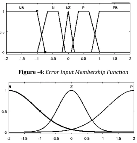
For quadrotor control triangular, trapezoid and Gaussian [image:3.595.37.269.155.398.2]membership functions are used. Input range is from [-2, 2] whereas output variable lies in the range of [-15, 15]. Following are the membership defined for each controller.
[image:3.595.38.263.430.540.2]Figure -4: Error Input Membership Function
[image:3.595.311.558.442.543.2]Figure -5: Derivative of Error Input Membership Function
Figure -6: Output Membership Function
[image:3.595.343.503.611.717.2]The simulation in this paper is using the parameters as mentioned in Bouabdallah PHD thesis as shown in table below [5].
Table -2: Quadrotor Parameters
IXX 0.0075
IYY 0.0075
IZZ 0.0130
Jr 6.50x10⁻⁵
B 3.13x10⁻⁵
D 7.50x10⁻⁵
L 0.23
M 0.65
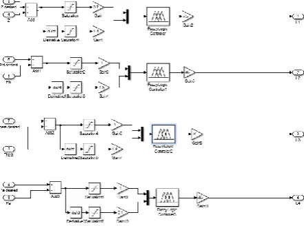
Simulink is used to develop the controller. For the control of quadrotor four Fuzzy type controllers are used in order
to achieve the desired output. In this paper we are only going to discuss the Roll Controller and rest remains similar.
For the purpose to control the roll angle of the quadrotor control input can be defined as [10]
U2=Kp.(ϕd-ϕ)+Kd.(ϕ d-ϕ (3)
Where
U2: Control Input Kp: Proportional Gain Kd: Derivative Gain ϕd: Roll Desired ϕ: Actual Roll
The equation above can be implemented in Simulink as shown in figure below. Saturation blocks are used in the design of the controller to avoid the any situation that can take value out of the defined range.
Figure -7: Fuzzy Roll Controller
[image:3.595.78.248.635.739.2]Fuzzy rules surface can be seen in the figure below
Figure -8: Fuzzy rules surface Where
N: Negative Z: Zero
P: Positive GUM: Go Up Much
GU: Go Up S: Stand
GDM: Go Down Much GD: Go Down
© 2017, IRJET | Impact Factor value: 5.181 | ISO 9001:2008 Certified Journal
| Page 1497
4. Simulation and Results [image:4.595.46.267.177.341.2]General Scheme of all controllers in Matlab is shown in the picture below
Figure -9: Controller Block Diagram
Here in this case the desired input is unit step and desired output is also unit step. Simulation results with respect to the desired input is shown in the figures below
Figure -10: PHI Response
Figure -11: Theta Response
[image:4.595.58.567.422.795.2]Figure -12: PSI Response
Figure -13: Z/Altitude Response
5. CONCLUSIONS
In this paper a nonlinear mathematical model of quadrotor is presented and implementation of the presented model is done through Matlab/Simulink. The presented model also considered rotor dynamics and aerodynamic effects which in most of the literatures are not considered during modeling. By looking at the responses shown in figures above we can observe that the behavior of Roll, Pitch, Yaw and Z are almost the same as the provided input. Further investigation can be made by using the same controller design and implement it on hardware.
REFERENCES
[1] Quadrotor HQ. (2013, August) QUADCOPTER HQ.
[Online]. HYPERLINK
"http://quadcopterhq.com/what-is-a-quadcopter/" http://quadcopterhq.com/what-is-a-quadcopter/ [2] Y. Aghli,M. Alimohammadi,A. A. Akbari S. Norouzi
Ghazbi, "Quadrotors unmanned aerial vehicles : A review," vol. 9, no. 1, 2016.
[3] Pavel Chmelař, "BUILDING AND CONTROLLING THE QUADROCOPTER," vol. VI, 2011.
© 2017, IRJET | Impact Factor value: 5.181 | ISO 9001:2008 Certified Journal
| Page 1498
Modeling and Control of a Quadrotor Using Linearand non linear approach," Cairo, 2014.
[5] Samir BOUABDALLAH, "Design and Control of quadrotors with application to autonomous flying ," Lausanne, 2007.
[6] Mohammad Bagher Menhaj,Roland Siegwart Fardin Fakurian, "FUZZY CONTROLLER DESIGN FOR QUADROTOR UAVS USING MINIMAL CONTROL INPUT," , Tehran, 2014.
[7] Muhammad Shoaib Nizami, "Development of a Fuzzy Logic Controller for a Distillation Column Using Rockwell Software," Ontario, Canada, 2011.
[8] Stephen Yurkovich Kevin M. Passino, Fuzzy Control. California: Addison Wesley Longman, Inc., 2725 Sand Hill Road, Menlo Park, California 94025, 1998. [9] Prof. ir. H.B. Verbruggen, Fuzzy Logic in Control.
Amsterdam: Technische Universiteit Delft, 1995. [10] Abdel-Razzak MERHEB and Hassan NOURA, "Novel
Bioinspired Stochastic Tuning of a Quadrotor PD Controller," , Sydney, 2012 Australian Control Conference.
BIOGRAPHIES
Muhammad Awais Sattar is a graduate of Electrical Engineering from Comsats Institute of technology Lahore (CIIT) and currently pursuing his Master’s degree in Electrical Engineering, specializing in Control System, at Rochester Institute of Technology (RIT), Dubai Campus.