© 2018, IRJET | Impact Factor value: 6.171 | ISO 9001:2008 Certified Journal | Page 2371
Analysis of RCC Culvert By Using Software
Pooja Shende
1, Prof. Manish Chudare
21M.Tech Student, Department of Structural Engineering, T.G.P.C.E.T, Nagpur, Maharashtra 2Assistant Professor, Department of Structural Engineering, T.G.P.C.E.T, Nagpur, Maharashtra
---***---Abstract -
In this paper analysis of culvert by using software for different L/H ratio with angle of friction. Culverts are provided to allow water to pass through the embankment and follow natural course of flow and road passes and culverts are also provided to balance the water level on both sides of embankment during floods, such culverts are termed as balancers.The structural design of a reinforced concrete box culvert comprises the detailed analysis of rigid frame for moments, shear forces and thrusts due to various types of loading conditionsKey Words: Staad pro, culvert, L/H ratio, Angle of friction
1. INTRODUCTION
A culvert is any structure not classified as a bridge that provides an opening under a roadway, and other type of access or utility. It is well known that roads are generally constructed in embankment which comes in the way of natural flow of storm water (from existing drainage channels). The structural design of a reinforced concrete box culvert comprises the detailed analysis of rigid frame for moments, shear forces and thrusts due to various types of loading conditions outlined below:
1. Concentrated Loads 2. Uniform Distributed Loads 3. Weight of Side Walls
4. Water Pressure inside Culvert 5. Earth Pressure on Vertical Side Walls 6. Uniform Lateral Load on Side Wall
In finite element methodology; One of the main objectives of selecting a numerical model is to reduce the infinite degrees of freedom system to a limited degree of freedom, which will represent the significant physical behavior of the system. Numerical methods are most frequently using to get those solutions of the problems. So we are discretizing the problem by using Finite element techniques because of its practicality and versatility.
Procedure for computational modeling using FEM:
_ Modeling
_ Meshing (Discretization) _ Specification of material _ Assigning Restrains _ Applying Loading
2. OBJECTIVES
1) To study the effect of cushion in RCC culvert by analysis for different cases like traffic condition, Soil condition, hydrological condition.`
2) Structural designing of RCC culvert considering various load cases including factors like effective live loads, effective width, and coefficient of earth pressure. 3) The principal objectives of the project are to investigate
basic parameters like shear force and bending moments for culvert with and without cushion.
3. LITERATURE REVIEW
1) B.N. Sinha, R.P. Sharma (2009):This Paper deals with box culverts made of RCC, with and without cushion. The size, invert level, layout etc. are decided by hydraulic considerations and site conditions. The cushion depends on road profile at the culvert location. The scope of this Paper has been further restricted to the structural design of box. The structural design involves consideration of load cases (box empty, full, surcharge loads etc.) and factors like live load, effective width, braking force, dispersal of load through fill, impact factor, co-efficient of earth pressure etc.
2) Miss Apurva J Chavan, Prof K.K.Tolani, Prof Chetan G. Joshi(2017): In this research, a steel box girder is analyzed by ANSYS program. The objective of this analysis is to model the box girder in an ANSYS FEM design. This task involves examining the stress patterns obtained using static three-dimensional finite element modeling.
3) Y. Vinod Kumar, Dr. Chava Srinivas(2015):In this paper we also study about design of box culvert and comparative study of reinforcement details. Vent size of the culvert is fixed based on flood discharge from upstream side. Clear dimensions of the box culvert is 3mX3m. Thickness of slab is 400mm.Grade of concrete is M30, grade of steel is Fe415 and angle of repose is 300.
4. METHODOLOGY
© 2018, IRJET | Impact Factor value: 6.171 | ISO 9001:2008 Certified Journal | Page 2372 2) Net ultimate bearing capacity , Earth pressure on
walls ,Deck slab Axial forces ,Side Wall Axial forces, Deck slab Shear forces ,Side wall Shear forces ,Base slab Shear forces , Deck slab Bending moments
3) Modeling and analysis of culvert by STAAD pro.
5. MODELING AND ANALYSIS
5.1 Problem statement
[image:2.595.120.206.252.338.2]The RCC Culvert is analyzed is for dead load, live load, earth pressure & water pressure using STAAD-Pro software.
[image:2.595.295.566.318.554.2]Figure 4.1Elevation of RCC box culverts
Figure 4.2 Isometric view of RCC box culverts
Figure 4.33D view of RCC box culverts
5.2 Properties
Top slab thickness – 300mm Side wall thickness – 300mm Bottom slab thickness – 300mm Grade of concrete – M30 Grade of steel – Fe550
5.3Loads on culverts
Dead load:: Self weight of culvert
Live load :: 166.5 kN/m²
Dry earth pressure:: 42.7 kN/m² Submerged earth pressure :: 19kN/m² Water pressure :: 30 kN/m²
5.4 Load combinations
Dead load+Dry earth pressure
Dead load+Dry earth pressure + Live load Dead load+ Submerged earth pressure
Dead load+ Submerged earth pressure+Live load Submerged earth pressure+ Water pressure
Submerged earth pressure+ Water pressure+Live load
6. RESULTS AND GRAPHS
6.1 Introduction
The RCC box Culvert with angle of internal friction Φ = 18,22,25,28,30 and L/H ratio = 1, 1.5, 2
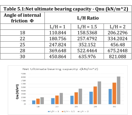
Figure 5.1: Net ultimate bearing capacity - Qnu (kN/m^2)
Table 5.2:Earth pressure on walls - Pnu (kN/m^2) Angle of internal
friction Φ L/H Ratio
L/H = 1 L/H = 1.5 L/H = 2 18 42.745619 96.177643 170.982477 22 36.839617 82.889139 147.358469 25 32.861801 73.939052 131.447204 28 29.230685 65.769041 116.922739 30 26.986861 60.720438 107.947446 Table 5.1:Net ultimate bearing capacity - Qnu (kN/m^2) Angle of internal
friction Φ L/H Ratio
L/H = 1 L/H = 1.5 L/H = 2 18 110.844 158.5368 206.2296 22 180.756 257.4792 334.2024
25 247.824 352.152 456.48
28 369.648 522.4464 675.2448
[image:2.595.115.207.374.460.2]© 2018, IRJET | Impact Factor value: 6.171 | ISO 9001:2008 Certified Journal | Page 2373 Figure 5.2: Earth pressure on walls - Pnu (kN/m^2)
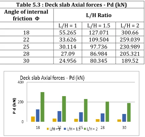
Table 5.3 : Deck slab Axial forces - Pd (kN) Angle of internal
friction Φ L/H Ratio
L/H = 1 L/H = 1.5 L/H = 2 18 55.265 127.071 300.66 22 33.626 109.504 259.039 25 30.114 97.736 230.989
28 27.09 86.984 205.321
30 24.956 80.345 189.52
[image:3.595.319.565.81.309.2]Figure 5.3: Deck slab Axial forces - Pd (kN)
Table 5.4 : Side Wall Axial forces - Pd (kN) Angle of internal
friction Φ L/H Ratio
L/H = 1 L/H = 1.5 L/H = 2 18 281.558 292.161 302.764 22 281.558 292.161 302.783 25 281.558 292.161 361.934 28 281.558 292.161 302.764 30 281.558 292.161 302.764
Figure 5.4: Side Wall Axial forces - Pd (kN)
[image:3.595.37.289.214.452.2]Figure5.5: Deck slab Shear forces -Vd (kN)
Table 5.6 : Side wall Shear forces -Vd (kN) Angle of internal
friction Φ L/H Ratio
L/H = 1 L/H = 1.5 L/H = 2 18 66.418 163.437 385.032 22 43.277 141.112 332.199 25 38.824 126.162 318.096 28 34.794 112.432 264.07 30 32.282 103.941 244.041
Figure 5.6: Side wall Shear forces -Vd (kN)
Table 5.7 : Base slab Shear forces -Vd (kN) Angle of internal
friction Φ L/H Ratio
L/H = 1 L/H = 1.5 L/H = 2 18 230.206 239.046 248.895 22 229.938 239.003 249.058 25 229.93 238.411 297.27 28 229.265 237.897 249.04 30 229.919 237.52 248.866 Table 5.5 : Deck slab Shear forces -Vd (kN) Angle of internal
friction Φ L/H Ratio
[image:3.595.311.556.340.583.2] [image:3.595.36.278.486.731.2]© 2018, IRJET | Impact Factor value: 6.171 | ISO 9001:2008 Certified Journal | Page 2374 Figure 5.7: Base slab Shear forces -Vd (kN)
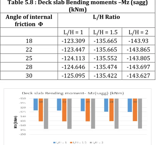
Table 5.8 : Deck slab Bending moments –Mz (sagg) (kNm)
Angle of internal
friction Φ L/H Ratio
L/H = 1 L/H = 1.5 L/H = 2 18 -123.309 -135.665 -143.93 22 -123.447 -135.665 -143.865 25 -124.113 -135.552 -143.805 28 -124.646 -135.474 -143.697 30 -125.095 -135.422 -143.627
[image:4.595.310.556.67.318.2]Figure 5.8: Deck slab Bending moments -Mz(sagg) (kNm)
Table 5.9 :Side wall Bending moments -Mz(sagg) (kNm)
Angle of internal
friction Φ L/H Ratio
L/H = 1 L/H = 1.5 L/H = 2 18 -79.965 -119.87 -284.67 22 -74.481 -110.52 -251.01 25 -73.526 -103.95 -348.26 28 -72.737 -97.953 -208.64 30 -72.124 -94.216 -196.13
Figure 5.9: Side wall Bending moments -Mz(sagg) (kNm)
Table 5.10 : Base slab Bending moments -Mz(Hogg) (kNm)
Angle of internal
friction Φ L/H Ratio
L/H = 1 L/H = 1.5 L/H = 2 18 119.38 126.486 133.443 22 120.325 126.486 132.809 25 121.145 125.42 164.099 28 121.177 124.679 131.144 30 122.355 124.19 130.443
Figure 5.10 :Base slab Bending moments -Mz(Hogg) (kNm)
6. CONCLUSIONS
1. Net ultimate bearing capacity –Qnu of box culvert is increased by 25%as angle of internal friction and L/H ratio are increased.
2. Earth pressure on walls –Pnu of box culvert is decreased by 15% as angle of internal friction is increased but it is increased by 50% as L/H ratio is increased.
3. Deck slab Axial forces –Pd of box culvert is increased by 15% as angle of internal friction is increased but it is increased by 50% as L/H ratio is increased.
4. Side Wall Axial forces –Pd of box culvert is found to be same as angle of internal friction is increased but it is increased by 10% as L/H ratio is increased.
5. Deck slab Shear forces –Vd of box culvert is found to be same for all models.
6. Side wall Shear forces –Vd of box culvert is decreased by 15% as angle of internal friction is increased but it is increased by 50% as L/H ratio is increased.
7. Base slab Shear forces –Vd of box culvert is found to be same as angle of internal friction is increased but it is increased by 10% as L/H ratio is increased.
[image:4.595.34.290.233.470.2] [image:4.595.39.291.511.748.2]© 2018, IRJET | Impact Factor value: 6.171 | ISO 9001:2008 Certified Journal | Page 2375 9. Side wall Bending moments -Mz(sagg) of box culvert is
decreased by 15% as angle of internal friction is increased but it is increased by 50% as L/H ratio is increased.
10. Base slab Bending moments -Mz(Hogg) of box culvert is found to be same as angle of internal friction is increased but it is increased by 10% as L/H ratio is increased.
7. REFERENCES
1) C. LANDE, S. K. KAMANE, S. A. MAHADIK,”Finite Element Analysis of Box Culvert “, International Journal of Advanced Structures and Geotechnical Engineering ISSN 2319-5347, Vol. 04, No. 01, January 2015 IJASGE 040111 Copyright © 2015 BASHA RESEARCH CENTRE. All rights reserved
2) Neha Kolate, Molly Mathew, Snehal Mali,”Analysis and Design of RCC Box Culvert”International Journal of Scientific & Engineering Research, Volume 5, Issue 12, December-2014ISSN 2229-5518
3) Y. Vinod Kumar, Dr. Chava Srinivas,” ANALYSIS AND DESIGN OF BOX CULVERT BY USING COMPUTATIONAL METHODS”, ISSN 2277-2685 IJESR/July 2015/ Vol-5/Issue-7/850-861, International Journal of Engineering & Science Research
4) Miss Apurva J Chavan, Prof K.K.Tolani , Prof Chetan G. Joshi,” REVIEW ON BOX GIRDER CULVERT ANALYSIS USING ANSYS”, International conference on recent trends in civil engineering, science and management, 2017.
5) B.N. Sinha & R.P. Sharma,” RCC BOX CULVERT - METHODOLOGY AND DESIGNS INCLUDING COMPUTER METHOD”, Journal of the Indian Roads Congress, October-December 2009.
6) Siva Rama Krishna, Vaddeswaram, Guntur, Ch. HanumanthaRao,”STUDY ON BOX CULVERTSOIL INTERACTION”, International Journal of Civil Engineering and Technology (IJCIET)Volume 8, Issue 1, January 2017
7) Saurav , Ishaan Pandey ,”ECONOMIC DESIGN OF RCC BOXCULVERT THROUGH COMPARATIVESTUDY OF CONVENTIONAL ANDFINITE ELEMENT METHOD”, International Journal of Engineering and Technology (IJET) Vol 9 No 3 Jun-Jul 2017
8) Kyungsik Kim & Chai H. Yoo., “Design Loading on DeeplyBuried Box Culverts” Journal of Geotechnical and Geo environmental Engineering, Vol. 131, No.1, January1, 2005, @ASCE, ISSN 1090-0241/2005/1-20-27.
9) Terzaghi and Karl, “Theoretical soil Mechanics” JohnWiley and Sons, ING, 1962.
practicefor road Bridges”, Section II.
12)IRC : 21-2000, “Standard Specification and code ofpractice for road Bridges” , Section III
13)Ramamurtham & R.P.Sharma., “RCC Box Culvert Methodology and Designs including Computer method” Journal of the Indian Roads Congress, October-December2009, Paper 555.