© 2017, IRJET | Impact Factor value: 5.181 | ISO 9001:2008 Certified Journal | Page 239
MECHANICAL DESIGN AND ANALYSIS OF STEEL STACK BY VARYING ITS
HEIGHT WITH CONSTANT DIAMETER
Kalagouda R Patil
1, Dr. B S Manjunath
21
Department of Mechanical Engineering (M.Tech in Design Engineering)
KLE Dr. M S Sheshgiri College of Engineering and Technology Udyambag, Belagavi, Karnataka, India 590008
2
Department of Mechanical Engineering (Professor)
KLE Dr. M S Sheshgiri College of Engineering and Technology Udyambag, Belagavi, Karnataka, India 590008
---***---Abstract -
Chimneys are tall and slender structures whichare used to discharge waste/flue gases at higher elevation with sufficient exit velocity such that the gases and suspended solids(ash) are dispersed in to the atmosphere over a defined spread such that their concentration , on reaching the ground is within acceptable limits specified by pollution control regulatory authorities. This project summarizes the analysis and design concepts of chimneys as per Indian codes provisions incorporation was also made through finite element analysis. Chimney models are designed on the basis of constant diameter with change in height taken into consideration. These models are analyzed by finite element software STAAD Pro, ANSYS, emphasis also placed on effect of geometric limitations on the design aspects in designing chimney. The main objective of this study the design and constructional aspects of steel stack (with particular reference to steel plant) adhering to the guidelines given in internationally accepted standards/codes. Therefore, objective of this study was to take a practical case study and carry out design calculations by using the rules of codes viz., IS: 6533 part 1 and 2, IS: 875 part-3, IS: 1893 part1 and 4. Further to get full insight into the design of the steel stacks a complete 3-D finite element analysis was carried out by using ANSYS software. Results have been summarized and conclusions have been drawn.
Key Words: Finite Element Software STAAD Pro, ANSYS,
IS: 6533 part-1 and part-2, IS: 875 part-3, IS: 1893 part-1 and part-4.1.
INTRODUCTION
Stacks as we know them today are tall slender structures which fulfill an important function. They had a humble beginning as household vents and over the years, as vent grew larger and taller they came to be known as chimneys/stacks. Steel stacks are ideally suited for process work where a short heat up period and low thermal capacity are required where as it encourages acid condensation and corrosion hence smutting and reduction in the life of stack. A chimney which was scientifically designed to take cognizance of gas temperature and velocity, corrosion aspects etc was called a stack. By usage the term stack has gained popularity and today it also signifies a chimney.
2.
STATEMENT OF PROBLEM, OBJECTIVES AND
CONSTRUCTION MATERIALS
Design analysis of 1.9m ID and varying heights of 30, 40, 50 and 60m height steel stacks to be used in “Salem” steel plant.
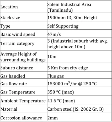
Table -2.1: Input data for steel stack design from Salem steel plant
Location Salem Industrial Area (Tamilnadu)
Stack size 1900mm ID, 30m Height Type Self Supporting
Basic wind speed 47m/s
Terrain category 3 (Industrial suburb with avg. height above 10m)
Average Height of
surrounding buildings 10m
Suburb distance 5 Km from city edge Gas handled Flue gas
Gas flow rate 153000 m³/hr @ 250 °C Gas Temperature 350 °C (max)
Ambient Temperature 41.6 °C (max)
Material Carbon steel(IS: 2062 Gr. B) Corrosion allowance 2mm
2.1: OBJECTIVES
[image:1.595.316.551.341.598.2]© 2017, IRJET | Impact Factor value: 5.181 | ISO 9001:2008 Certified Journal | Page 240
2.2: CONSTRUCTION MATERIALS
1. Stack shell – Carbon steel – IS: 2062 Gr. B (weldable grade) 2. Bolting material – 8.8 Gr. (IS: 1363/1364)
3. Platforms and ladders – St – 42 (structural steel IS: 2062)
3.
ASSUMPTIONS MADE DURING DESIGN
Following are the assumptions made during the design of steel stack.
1) The wind pressure varies with the height. It is zero at the ground and increase as the height increases. For the purpose of design it is assumed the wind pressure is uniform throughout the height of the structure.
2) For the purpose of calculations, it is assumed that the static wind load (projected area multiplied by wind pressure) is acting at the center of pressure.
3) In calculating the allowable stresses both tensile and bending, the Joint efficiency for butt welds is assumed to be 0.85.
4) The base of the stack is perfectly rigid and the effect of gussets and stool plate on the deflection and the stresses in the stack is not considered. This is applicable only for manual calculations.
5) There are no additional lateral movements from the duct transferred to the stack and Suitable arrangement has to be provided to absorb this movement from the duct.
6) Since the D/t ratio (mean diameter of stack to thickness of plate) is greater than 10, the structure is a thin cylinder and shell (plate) element can be used for finite element modeling.
7) Earthquake causes impulsive ground motions, which are complex and irregular in character, changing in period and amplitude each lasting for a small duration. Therefore, resonance of the type as visualized under steady state sinusoidal excitations will not occur, as it would need time to build up such amplitudes.
8) Earthquake is not likely to occur simultaneously with maximum wind or maximum flood or maximum sea waves.
4. METHODOLOGY
1) The stack is a cantilever system subjected to wind and earthquake loads. In order to determine the wind force acting on the stack, the stack is divided into number of zones. The zoning of the stack depends on the maximum plate width available for a particular thickness and capacity of the lifting equipment at the time of erecting of the stack. Normally the height of each zone is between 2.5m to 5m and typically 4m if the stack is to be welded at the site of location. In the current design calculations, the height of zone has been fixed at 5m after consultations with the client as well as fabricator (Refer layout drawing A-1 of Annex F).
2) The bending moment at the end of each zone is determined to find the required section modulus and hence the thickness.
3) The deflection at the top of the stack is calculated and checked against the allowable limits. In case the deflection at the top is more, and then the section modulus at the base of the stack is increased till the deflection is within limits. If, however, it is not possible to contain the deflection in spite of increasing the section modulus, the stack is guided at 2 or more locations. 4) The natural frequency is determined to check if the
dynamic effect of the wind needs to be taken care during the design stage.
5) The check for resonance is carried out.
5. DESIGN MANUAL CALCULATIONS
5.1: DESIGN PARAMETRS
1. Deflection in mm
2. Compressive Stress in MPa 3. Natural Frequency in Hz
Deflection is given by the equation:
………5.1
Where,
X=Deflection in mm.
W=Total force acting on each zone. L=Length of stack in mm.
a=Distance from base to the point of force acting. E=Young’s modulus= 2.1×10⁵MPa.
I=Moment of inertia in mm4.
………5.2
Deflection is calculated by using equation 5.1 for each zone and adding all X=187.49mm In practice since the stack is tapered and thickness also varies along the height, taking the coefficient for the variation from Roark’s formula for stress-strain,
X=187.49×0.4248 X=79.64mm
Natural frequency is given by the equation:
………..5.3
Where,
f=frequency in Hz.
© 2017, IRJET | Impact Factor value: 5.181 | ISO 9001:2008 Certified Journal | Page 241 meters.
g=Rate of gravitational acceleration=9.81m/s².
Table-5.1: Showing the weight of each zone
Table-5.2: Showing x and mx2 to calculate frequency
f=3.09Hz
Compressive stress is given by equation:
The stress at the base of the stack is determined by;
………5.4
Where, σ= compressive stress in MPa. M= Bending moment in N-mm Z= Section modulus in mm3.
Compressive stress=50.35MPa
6. VALIDATIONS OF MANUAL RESULTS BY FEA
USING ANSYS
6.1: ANALYSIS PROCEDURE
The manual calculations are compared with the analysis results to validate the assumptions made and later the complete model with all the main features like, stool plate, base plate, gussets, platform, breach opening and
manhole opening are made to simulate the actual construction. The platform supporting structure is made out of beam element (Beam – 188). The stack is fixed at anchored bolt points. Now in this case the base of stack is fixed rigidly with all DOF fixed. The figure 7.2 shows the meshed model and boundary conditions. The steps involved in analysis are as follows
1) Create layout drawings using AutoCAD. 2) Create actual model in Catia/ Ansys.
3) Mesh the modal, specify the material properties, and apply loads and boundary conditions.
4) Extract the required results, Deflection, stresses, Natural frequency etc
6.2: LOADING
Following loading where considered Total wind load = 228989N Total weight = 11332.9N Imposed load on platforms = 2.943x10⁻³N/mm2
6.3: BONDARY CONDITIONS
The base of stack was fixed with all degrees of freedom and resultant force as calculated earlier was applied at the center of each zone. For further analysis shell is welded to base plate of given thickness, anchor bolts of calculated size are used to fix at the base. The same effect was transmitted to FEM model, by fixing at the determined bolt locations with all degree of freedom fixed.
FIG: 6.1 Shows the boundary conditions for the analysis of the stack with base fixed rigidly with all DOF fixed. zone Thickness t
in mm OD in mm
ID in mm
Area in mm²
Volume (v) in mm³
Mass ρ×v in Kg
Weight in N
1 25 1950 1900 151189 755945732 5941 58288.4
2 20 1940 1900 120637 603185750 4741 46509.5
3 16 1032 1900 96308 481543321 3785 37130
4 12 1924 1900 72080 360403509 2832 27789
5 10 1920 1900 60004 300022098 2358 23134
6 8 1916 1900 47953 239766351 1884 18482
Total 21453 211332
Zone Mass in kg Deflection in mm (x) x2 mx mx2
1 5941 3.84 14.7 22816.2 87614
2 4741 11.50 132.3 54521.8 62000121
3 3784 19.16 367.1 72519.2 1389468
4 2832 26.83 719.8 76003.2 2039166
5 2358 34.50 1190.2 81356.8 28066811
6 1884 42.16 1777.4 79453.4 3349740
© 2017, IRJET | Impact Factor value: 5.181 | ISO 9001:2008 Certified Journal | Page 242
6.4: ANALYSIS RESULTS
The results from ANSYS are shown below and comparison with the manual calculations is summarized in table below.
1. Deflection in mm at the top of stack
FIG: 6.2 Deflection at the top of the stack for analysis with base fixed rigidly.
2. Compressive stress in MPa at the base of stack
FIG: 6.3 Compressive stress at the base of the stack for analysis with base fixed rigidly.
3. Von misses stress in MPa at the base of the stack
FIG: 6.4 Von misses stress at the base of the stack for analysis with base fixed rigidly.
6.5: RESULIT SUMMERY
Table-6.1: Tabulation of results to compare manual results with FEA results.
Parameters calculation Manual Analyzing using ANSYS
Percentage of variation
w.r.t to ANSYS Deflection in
mm 79.69 73.18 8.16%
Compressive stress in
MPa
52.63 50.35 4.33%
Natural frequency in
Hz
3.06 3.18 -4%
Note: The manual calculations assume that the base of stack is rigid i.e. the elastic rigidity of bolts and foundation is neglected. The same has been simulated in Ansys by fixing all DOF at the base of the stack.
CONCLUSION:
© 2017, IRJET | Impact Factor value: 5.181 | ISO 9001:2008 Certified Journal | Page 243
REFRENCES:
[1] IS: 875 (Part 3–1987), Indian standard, Code of practice for design of loads (other than earthquakes) for buildings and structures, part 3(wind loads). Bureau of India Standards, New Delhi.
[2] IS: 6533 (part1): 1989 I n d i a n standard, Design and construction steel chimneys - code of practice (Mechanical Aspects), Bureau of Indian standards, New Delhi.
[3] IS: 6533 (PART-2):1989 Indian standard, Code of practice of design and construction steel chimneys (structural Aspect), Bureau of Indian standards, New Delhi.
[4] IS: 1893 (part4–2005), Criteria for earthquake resistant design of structures including stack- like structures (Earthquake resistant) , Bureau of Indian standards, New Delhi.
[5] Ramchandra and Virendra G. Design of steel structures-2, Standard book house Delhi, 7th Edition 1991.