AN IMPROVED MODEL FOR SYMBOL RATE ESTIMATION
BASED ON WAVELET TRANSFORM
1MINGWEI QIN, 2TAO DAI, 3WEI LIU
1,3 School of Information Engineering, Southwest University of Science and Technology, Mianyang,
621000, China
2 The Institute of Electronic Engineering, China Academy of Engineering Physics, Mianyang, 621000,
China
E-mail: [email protected], [email protected], [email protected]
ABSTRACT
In non-cooperative communication system, symbol rate is a crucial part of parameter estimation. Based on the wavelet transform, an improved symbol rate estimation model is proposed. Without a prior knowledge, we raised a better symbol rate pre-estimation method in view of corrected average periodogram’s smoothing power spectrum. By choosing the optimal wavelet scale and fast Fourier transform, we adopted a multi-synchronous reference algorithm to extract the symbol rate. Simulation demonstrates that the performance of accuracy and anti-noise is improved than traditional algorithms. The normalized mean square is lower than 10-2 at SNR=0dB and reached 10-5 when SNR=10dB, which is approaching more closely to CRLB.
Keywords: Symbol Rate Estimation; Wavelet Transform; Optimal Scale; Non-Cooperative
Communication; Multi-Synchronous Reference; Fast Fourier Transform; Corrected Average Periodogram’s Smoothing Power Spectrum.
1.INTRODUCTION
Non-cooperative communication is not only applied in electronic warfare and intercepting communication intelligence, but also has a great value in military communication and civilian communication. However, the current research is focus on estimating parameters and identifying modulation types of the received signals under low SNR. Symbol rate estimation, which is an important part of parameter estimation, has a great significance on identification and signal demodulation. Wavelet transform, which has excellent location properties and noise suppression properties, is widely used in the extraction of instantaneous parameters[1]. For PSK signal, wavelet transform has very good ability to capture the transient characteristics when the phase changes.
Chan first proposed the theory of wavelet transform to estimate the symbol rate [2], and combine the coefficients over several scales to improve the accuracy of the estimator, but the algorithm has weak ability of anti-noise. Xu analyzed the defects in choosing wavelet scale and weak ability of anti-noise in Chan’s algorithm [3],
modification is moving the carrier frequency of received signal to zero before wavelet transform, but it is quite sensitive to vestigial frequency shift and not stable. After that, a series of algorithms based on the wavelet transform coefficient and auto-correction has been proposed: Ho applied the autocorrelation of WT coefficients to estimate symbol rate at moderate SNR [4]. Sun adopted a cyclic correlation algorithm [5] and Gao employed the morlet wavelet transform and autocorrelation [7] to estimate symbol rate under Doppler channel. They got a better estimation results, however, it needs a great number of samplings and intensive computation.
In addition, there still have some problems been ignored: a). The importance of the pre-estimation of symbol rate, which is made only a simple assumption and contrary to no a prior knowledge. b) The selection of the best wavelet scale. Although the mult-scale wavelet transform can overcome the interference of noise in some extent, it can not effectively overcome the strong noise interference. c) the extraction algorithm, which has strong ability to counteract noise interference.
ISSN: 1992-8645 www.jatit.org E-ISSN: 1817-3195
filter model and raised cosine shaping filter model. Meanwhile, a new calculation method based on the perspective of the power spectrum is proposed; then select the best wavelet scale, and combine with FFT(fast Fourier transform), a new algorithm based on multi-synchronization reference points is raised to extract the symbol rate of PSK signal. At last, an improved symbol rate estimation model has been proposed. Simulation improves the accuracy and precision of symbol rate estimation at low SNR using the improved model.
In Section II, the two pulse shaping filter models and theoretical results of wavelet transform is outlined. The MSR algorithm is discussed in detail in Section III and verified by comparing and analysis simulation results with the existing algorithms in Section IV. Finally, a conclusion is made in Section V.
2.SIGNALMODELANDWAVELET
TRANSFORM
Set the received complex signal [2] is:
( )
( )
( )
( )
( )
j w tc c( )
x t
=
s t
+
n t
=
s t e
+θ+
n t
(1)
Where s t( )is the modulated complex signal, ( )
n t is a complex additive Gaussian white noise
and 2 2
( ) 2
E n t = δε. And ωcis the carrier frequency, c
θ is the carrier phase. For PSK signal,
1 2
( ) i ( ) ( 1)
M j
T i
i m
s t E e g t iT m
M
φ φ π
= = − ∈ −
∑
, (2)Where E is the signal power, and gT(t) is the pulse shaping filter function, T is the symbol duration. For simplicity, assuming the signal
power
E
=
1
andθ =
c0
.2.1 Rectangular pulse shaping filter model
In this model,
g t
( )
satisfies:1 ,
0
( )
0 ,
t
T
g t
others
≤ <
=
(3) From eqn.2, symbol changing gives rise to transient in PSK signal, and the wavelet transform has excellent transient capability to detect andanalysis instantaneous change. The continuous wavelet transform of x t( )is defined as
* *
( , )
( )
( )
1
( )
(
)
a aCWT a b
x t
t dt
t
b
x t
dt
a
a
ψ
ψ
=
−
=
∫
∫
(4)Where
a
is the wavelet scale,b
is the translation, and ψa( )t is a mother wavelet function. The haar function (defined as 1 when−
0.5
< <
t
0
, -1 when0
< <
t
0.5
, and 0 otherwise), satisfies the condition of choosing optimal mother wavelet function [8][4], in addition, the corresponding wavelet transform is easy to compute and implement.The following derives the haar wavelet transform of PSK signals. When the haar function is within a symbol or continuous symbols as shown in figure 1a,
x t
( )
has a constant phaseφ
.Hence0 / 2
( ( ) ) ( ( ) )
/ 2 0
( , )
1
d d
c c
a
j t b j t b
a
CWT a b
e t e t
a
ω + +φ ω + +φ
− = +
∫
∫
(5)So, the magnitude square is
2 4
2
16
( , )
sin (
)
4
c
c
a
CWT a b
a
ω
ω
=
(6)When the haar function covers a phase changing as shown in figure 1b, there is
{
}
( ( ) )
/ 2
0 ( ( ) ) / 2 ( ( ) )
0 1
( , ) c
c c
d j t b a
a
j t b j t b
d
CWT a b e dt
a
e dt e dt
ω φ
ω φ α ω φ α + + − + + + + + + = + −
∫
∫
∫
(7)Where
α
is phase change,d
is the time instance when the phase changes relative to the centre of the wavelet. And the magnitude square of eqn.7 is2 2
2 4
2 2
16
( , ) (sin sin cos )
2 2
(sin cos 2sin( ) sin( ))
2 4 2 4
c c
c c
c
CWT a b d
a
a a
d
α α ω
ω
ω ω
α ω α
= − + + + (8)
continuous phase ranges, while appears singular value at the phase transition.
Figure 1 Haar wavelet positioning in PSK signal
2.2 Raised cosine shaping filter module
In raised cosine shaping filter model, time-domain waveform function is
2 2
2
sin(
)
cos(
)
g( )
4
1 (
)
t
t
T
T
t
t
t
T
T
π
απ
π
α
=
×
−
(9)Where
α ∈
(0,1]
is roll-off factor,T
is the symbol duration. The received signal after raised cosine shaping filter is~
( )
( )
[ ( ) * ( )]
j ct cs t
=
s t
g t
×
e
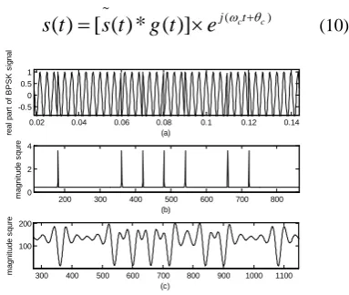
ω θ+ (10)0.02 0.04 0.06 0.08 0.1 0.12 0.14 -0.5
0 0.5 1
(a)
real
par
t of
B
P
S
K
s
ignal
200 300 400 500 600 700 800 0
2 4
(b)
m
agni
tude s
qur
e
300 400 500 600 700 800 900 1000 1100 100
200
(c)
m
agni
tude s
qur
e
Figure 2 The coefficient of CWT under two modules
For BPSK signal, Figure 2 shows the magnitude of wavelet transform coefficients with a=4 in the rectangular pulse shaping filter model and raised cosine pulse shaping filter model figure 2a shows the BPSK signal waveform; figure 2b gives the coefficients of wavelet transform in the rectangular pulse shaping filter model; and figure 2c shows the coefficients of wavelet transform in the raise cosine pulse shaping filter model. It can be seen that the distinct peaks are obvious when the haar wavelet covers a phase change, and the distance among the peak’s changing will give out a symbol period
estimation. By comparing the two models, we can see that the wavelet coefficient in the modulated signal at the phase transition point, there is a distinct spectral peaks at the rectangular pulse model, moreover, the interval between peaks is just an integer multiple of symbol rate, while others is a much smaller constant in the continuous waveform. However, in the raised cosine pulse shaping filter model, the transient behaviour of the wavelet transform is not well represented, because the wavelet coefficients of peak or valley by the inter-symbol interference (ISI) effects. The peak or valley does not have regular intervals which is no longer an integer multiple of symbol rate, so the symbol rate can not be effectively estimated. In summary, the wavelet transform is not suitable for the raised cosine pulse shaping filter model to estimate the symbol rate. But we still select the rectangular pulse model for further study to reflect the advantages of wavelet transform at symbol rate estimation.
3.PRE-ESTIMATIONOFSYMBOLRATE
The current study on symbol rate estimation is under the condition of known pre-estimated symbol rate value or the hypothetical symbol rate pre-estimation, which is contrary to no a prior knowledge. The value of pre-estimation is not only reducing the scope of selecting the optimal wavelet scale and the amount of computation, but also affects the final accuracy and precision. So, from the perspective of power spectrum analysis, we proposed a pre-estimated algorithm based on the corrected average periodogram’s smoothing power spectrum.
3.1 Corrected average periodogram’s
smoothing power spectrum
Set the direct periodogram power spectrum [6] is
2
1
( )
N( )
p
X
N
ω
=
ω
(11)1
0
( )
( )
n
j n N
n
X
ω
x n e
ω−
−
=
=
∑
(12)The main lobe of Direct periodogram in the frequency domain is not infinitely narrow, and there is large side lobes which make the main lobe’s energy ‘leaks’ to the side lobe, it makes the spectrum estimation undulating. On the analysis of the covariance of periodogram, we found that the periodogram value, which is an integer multiple of the frequency interval π , is not relevant. (a)
(b)
[image:3.612.105.297.398.560.2]ISSN: 1992-8645 www.jatit.org E-ISSN: 1817-3195
However, when the window length N increases, the interval reduce between the power spectrum of which covariance is zero. Therefore, the longer the window is, the more periodogram’s undulation is. To avoid this phenomenon, we set the sequence
x n
( )
into segments to obtain periodogram power spectrum and then averaging.Set the sequence be divided into L segments, there are M samples in each segment, the
ith
segment of sample sequence denoted
x n
i( )
, so the periodogram power is2 1
0
1
( )
( )
, 1
M
i i j n
M
n
I
x n e
i
L
M
ω
ω
− −=
=
∑
≤ ≤
(13)And its average is
1
1
( )
( )
L i
xx m
i
P
I
L
ω
ω
−
=
=
∑
(14)In order to calculate conveniently for the fast Fourier transform, we do two amendments. First, calculating the periodogram power with appropriate window function
w n
( )
, that is2 1
0
1
( ) ( ) ( )
M
i i j n
M
n
I x n n e MU
ω
ω − ω −
=
=
∑
(15)Where 1 2
0 1
( ) m n
U n
M ω
−
=
=
∑
is the normalizationfactor, which presents the average energy of the window function. Second, segment is able to overlap at most 50%, then the variance can be reduced to almost half of the original. Taking eqn.15 to eqn.14, we get the corrected average periodogram’s smoothing power spectrum.
3.2 Pre-estimation of symbol rate
With the corrected average periodogram’s smoothing power spectrum, we can get the
pre-estimated value
f
b'=
λ
B
3db , whereλ
is theweighting factor. The value of
f
b' has veryimportant influence on selection of the optimal wavelet scale and synchronization reference point. Because of the interference of noise, especially under lower SNR scenarios and in order to reduce error, we introduce the automatic adjustment weighted factor
λ
, which is[1,1.5].0 1000 2000 3000 4000 5000 6000 20
30 40
(a)
T
he pow
er
s
pec
tr
um
0 1000 2000 3000 4000 5000 6000 0
0.05 0.1 0.15 0.2
(a)
T
he pow
er
s
pec
tr
[image:4.612.324.517.78.228.2] [image:4.612.99.299.248.341.2]um
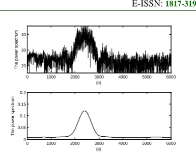
Figure 3 Power spectrum of BPSK with SNR=2dB
Figure 3 shows the power spectrum of BPSK signal with SNR=2dB. Figure 3a is the power spectrum calculated directly; while figure 3b uses the corrected average periodogram’s smoothing power spectrum algorithm to smooth power spectrum. By comparison, the spectrum in figure 3a has been serious interference by noise, and it is difficult to estimate the bandwidth, however, the spectrum in figure 3b is much more clear and smoothness. It is not only reduced the estimated degree of difficulty, but also improve the estimation accuracy.
4.THEOPTIMALSCALESELECTION
Eqn.6 and eqn.8 show that the wavelet scale
a
determines the wavelet transform coefficient, moreover, the peak value at the phase change-point is directly impacting on the symbol rate extraction. So the choice of scale parameter is essential. Combining the coefficients over several scales to avoid the selection of optimal scale, but the algorithm has weak ability of anti-noise. Actually, the small scale which has a serious influence by noise at low SNR, is not conducive to accurate estimation of the symbol rate; the larger the scale is, the more obvious in the noise suppression, however, if the scale is too large, it will reduce or even overwhelm local extreme value. Therefore, we proposed an optimal scale selection algorithm.Theoretically, there should be an optimal scale parameter. From the perspective of power spectrum analysis, at the optimal wavelet scale, the spectrum of the coefficient is much more prominent, and the energy has the largest proportion. That is
2
(1, ) 1
arg min(
/
(
( , ) )
N
a th i
W
fft cwt a i
∈
∑
=2
1
2
1
( ( ( , ) )
max ( ( , )
N i
i N
W fft cwt a i
fft cwt a i
=
≤ ≤
=
−
∑
(17)Where
N
is the data length. In order to effectively extract the interval symbol transitioninformation, the scale must satisfy:
int(
s ')
bf
th
f
≤
.By the pre-estimation of symbol rate, the range of
a
can be easily calculated. Meanwhile, we set the scale step is 2 to reduce the computational load.5.SYMBOLRATEEXTRACTION
The methods to extract symbol rate include fast Fourier transform, autocorrelation and cyclic autocorrelation. However, using autocorrelation of wavelet coefficients to estimate symbol rate needs high computation and the error is also large. Based on fast Fourier transform, We proposed a new multi-synchronous reference (MSR) algorithm to extract precisely the symbol rate. After fast Fourier Transform (FFT) of the WT magnitude, there will be a series of non-strictly periodic spectrums. The interval between adjacent spectrum is approximately integer multiple of symbol rate cycle. Select multiple synchronous reference points and correction, symbol rate can be extracted accurately.
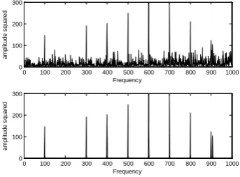
5.1 Extraction of MSR
Figure 4 gives the FFT magnitude of wavelet transform coefficient with SNR=2dB. The upper window shows that it is hard to extract symbol rate from so much irregular spectrum peaks, especially at the low SNR scenarios, though there have several salient periodic peaks. So, we first set a threshold
λ
to filter some lower peaks and remain some larger ones, obtained the spectrum like lower window in figure 4. Then, selecting the maxspectral peak as a synchronous reference point
f
i,0 1
max{
}
1, 2,...,
i i i
p
=
from p to p
i
=
N
Where
p
i is the pulse amplitude off
i, andN
is the number of synchronous reference points.The value of
λ
is very important to the number of synchronous reference point and accuracy. Therefore, the largerλ
0 is, the better anti-noise is.However, the value of
λ
is too large, the numberN
of symbol rate. Therefore, adjusting the threshold by using adaptive approach:
λ τλ
=
0 ,τ
is avariable weighted factor (we set initial value at 3),
and
λ
0 is the mean value of FFT magnitude.0 100 200 300 400 500 600 700 800 900 1000 0
100 200 300
Frequency
am
pl
it
ude s
quar
ed
0 100 200 300 400 500 600 700 800 900 1000 0
100 200 300
Frequency
am
pl
it
ude s
quar
[image:5.612.330.502.167.294.2]ed
Figure 4 The spectrum of wavelet coefficient
5.2 Accurate Estimate of Symbol Rate
Because of the noise interference and other factors, there maybe detect more than one reference points within one symbol rate cycle. To avoid this problem and extract the accurate symbol rate, we will discuss in detail as follows:
a. Selecting the previous maximum of
(
)
M M
<
N
fromp
i:p
j(
j 1,...,
=
M
)
b. Remove the smaller point of which thedistance between adjacent points is less than
γ
f
b' ,where
f
b'is the pre-estimated symbol rate,γ
is aweighted factor, set
γ
=
0.8
, and remains,
1,...,
(
)
l
p l
=
K K
≤
M
.
c. Selection synchronous reference points
once more: pick up all the points in
p
l , which distance between adjacent points is still lessthan
γ
f
b', set asp m
m,
=
1,...,
L
, and remains,
1,...,
n
p n
=
K
−
L
d. The final MSR:
set
p
=
max{
p m
m,
=
1,..., }
L
, so{
p p
n,
}
are corresponded to the synchronous referencepoints
{ ,
f
jj
=
1,...,
K
− +
L
1}
.ISSN: 1992-8645 www.jatit.org E-ISSN: 1817-3195
1 '
( j j )
j
b
f f n round
f
+ −
=
f. Accurate estimation of symbol rate ~
b
f
isas bellows:
~
1
1 1 K L
j j b
j j
f f f
K L n
− +
=
− =
−
∑
(18)6.THEOPERTATIONPROCESSAND
SIMULATION
The improved model of symbol rate estimation is shown in figure 5, and the process of the improved algorithm is summarized in the following. First, we do some preprocessing to the received signal, such as A/D、down sampling and filtering. After that, the frequency is located and moved to IF, then we couple the IF signal into two branches: one branch is to pre-estimate the symbol rate by the algorithm discussed above, and the optimal scale based on our algorithm is extracted; the other branch is to reduce the noise and improve SNR by using haar wavelet composition and reconstruction [8-10] After fast Fourier transform of the haar wavelet coefficients, there are several salient periodic spectrum peaks. Finally, by extracting the spectrum peaks with the multi-synchronous reference algorithm, the symbol rate is correctly estimated.
Pre-process
Wavelet denoising
Symbol rate extraction FFT
Optimal scale selection Wavelet transform
'
- fb
pre estimation
s(t)
~
b
[image:6.612.92.294.449.551.2]f
Figure 5 The operation process of improved algorithm
0 2 4 6 8 10 12 14 16 18 20 10-10
10-8 10-6 10-4 10-2
100
SNR/dB
RM
S
/d
B
2PSK 4PSK 8PSK 16PSK
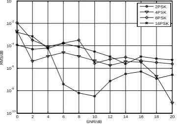
Figure 6 The performance on symbol rate estimation
In the simulation, the modulated parameters were set as
f
s=
10
f
c ,f
c=
3
f
d ,wheref
s is the sampling rate,f
cis the carrier rate andf
dis the symbol rate in theory. We set the normalized mean square error is~ 2 ( b b)
b
f f
RMS f
N
−
=
∑
(19)where ~
b
f
is the estimated symbol rate. The results were computed from 11000 times independent simulations. Figure 6 shows the normalized mean square error of our algorithm for different modulated signals in different SNR scenarios. The normalized mean square error is even lower than 10-2 while SNR=0dB. And it demonstrates that our algorithm is suitable for BPSK、QPSK、8PSK and 16PSK. Due to the noise interference, the fluctuation is available. When the SNR increases, the fluctuation becomes flat. Comparing with the original algorithms, our algorithm’s efficiency is obvious:15dB lower than HO’s [4], and 3dB lower than Xu’s [3], also has lower RMS and less computation than Gao’s [7], approaching more closely to CRLB.7.CONCLUSION
In the paper, we first in-depth analyze the wavelet transform of two shaping filter model. And then an improved model to symbol rate estimation is proposed to estimate symbol rate. The superiority is that pre-estimation and the selection of optimal scale is from the point of the power spectrum. By combining the optimal wavelet scale and fast Fourier transform, a new algorithm based on multi-synchronization reference point is raised to extract the symbol rate of PSK signal. Moreover, The algorithm is suitable for different modulation.
Simulation improves the performance of our algorithm. The normalized mean square error is reached 10-5 when SNR=10dB, and even lower than 10-2 at SNR=0dB.By comparing with the existence algorithms, the performance of accuracy and anti-noise is comparatively higher at lower SNR.
8.ACKNOWLEDGEMENT
[image:6.612.100.282.583.710.2]REFERENCES:
[1] Ingrid Daubechies.(1990) ‘The wavelet transform, time-frequency localization and signal analysis’, IEEE Transaction on Information theory, Vol 36, pp:961-1005.
[2] Y.T.Chan, J.W.Plews, and K.C.Ho.(1997) ‘Symbol rate estimation by the wavelet transform’, Proceedings of IEEE International Symposium on Circuits and Systems, Vol.1, pp. 177-180.
[3] Xu Jun, Wang Fu-ping, and Wang Zan-ji.(2005) ‘The improvement of symbol rate estimation by the wavelet transform’,
Proceedings. International Conference on Communications, Circuits and Systems, Vol.1, pp.100-103.
[4] K.C.Ho, W. Prokopiw, and Y.T.Chan.(2000) ‘Modulation identification of digital signals by the wavelet transform’, IEE Proceedings Radar, Sonar and Navigation, Vol.147, pp.169-176.
[5] Sun Gangcan, AN Jianping, and Yang Jie.(2008) ‘Symbol rate estimation using cyclic correlation and haar wavelet transform’, 4th International Conference on Wireless Communications, Networking and Mobile Computing, Beijing, China, October, pp:1-4. [6] P Welch.(1967) ‘The use of fast Fourier
transform for the estimation of power spectra: A method based on time averaging over short, modified periodograms’, IEEE transactons on Audio and Electroacoustics, Vol. 15, pp:70-73. [7] Yong Gao and Mu Li.(2009) ‘A symbol rate
estimation algorithm based on morlet wavelet wavelet transform and autocorrelation’, IEEE Youth Conference on Information, Computing and Telecommunication, Beijing, China, January, pp: 239-242.
[8] Q. Jin, K. M. Wong, and Q. Wu.(1994) ‘Optimum wavelet design for transient detection’, IEEE Statistical Signal and Array
Processing, Halimiton, Canada, June, pp.255-258.
[9] Stephane G, and Mallat.(1989) ‘A theory for multiresolution signal decomposition: the wavelet representation’, IEEE Transactions on Pattern Analysis and Machine Intelligence,
Vol.11, pp.674-693.
[10]David L. Donoho.(1995) ‘De-noising by soft-thresholding’, IEEE trans. On Information theory, Vol. 41, pp.613-627.
[11]Wei Liu, Yuancheng Yao and Mingwei Qin.(2011) ‘a multi-synchronous reference algorithm of symbol rate estimation’, 7th