DECnet
Digital Network Architecture
!
To order additional copies of this document, contact your local Digital Equipment Corporation Sales Office.
Maintenance Operations Protocol
Functional Specification
Version V4.0.0
June 1992
This document describes the structure, functions, interfaces, and protocols needed for the low level maintenance of a DECnet network.
This material may be copied, in whole or in part, provided that the copyright notice below is included in each copy along with an acknowledgement that the copy describes the Digital Network Architecture de-veloped by Digital Equipment Corporation.
The information in this document is subject to change without notice and should not be construed as a commitment by Digital Equipment Corporation. Digital Equipment Corporation assumes no responsibility for errors which may appear in this document.
All rights reserved Printed in U.S.A.
The following are trademarks of Digital Equipment Corporation:
DEBNA DEBNT DDCMP DEC DECconnect DECnet DECserver DECUS DELNI DELUA DELQA DEMPR
DEQNA DESQA DESVA DEUNA LANBridge Massbus PDP Q-bus RSX
RSX11M-PLUS ThinWire ULTRIX
Pr
ef
a
ce
iii
Preface
This document is one of a series of specifications which describe Phase Vof the Digital Net
-work Architecture. Other DNA Phase V specifications may be obtained by ordering one or more
of the following documentation kits:
DIGITAL NETWORK ARCHITECTURE (PHASE V) DOCUMENTATION KIT #1
Order No. EK-DNAP1-DK-001 includes:
Digital Network Architecture (Phase V) General Description, No. EK-DNAP
V-GD
Digital Network Architecture (Phase V) Network Services Protocol Functional Specification, No. EK-DNA15-FS-001
Digital Network Architecture (Phase V) Open Systems Interconnect Transport Functional Specification, No. EK-DNA12-FS-001
Digital Network Architecture (Phase V) X.25 Access Functional Specification, No. EK-DNA17-FS-001
DIGITAL NETWORK ARCHITECTURE (PHASE V) DOCUMENTATION KIT #2
Order No. EK-DNAP2-DK-001 includes:
Digital Network Architecture (Phase V) Session Control Functional Specifica
-tion, No. EK-DNA07-FS-001
Digital Network Architecture (Phase V) Naming Service Functional Specifica
-tion, No. EK-DNANS-FS-002
Digital Network Architecture (Phase V) Network Routing Layer Functional Specification, No. EK-DNA03-FS-001
Digital Network Architecture (Phase V)Unique Identifier Functional Specifica
-tion, No. EK-DNA16-FS-001
Digital Network Architecture (Phase V) Time ServiceFunctional Specification, No. EK-DNA04-FS-001
DIGITAL NETWORK ARCHITECTURE (PHASE V) DOCUMENTATION KIT #3
Order No. EK-DNAP3-DK-001 includes:
Digital Network Architecture (Phase V) High-Level Data Link Control Fun
c-tional Specification, No. EK-DNA08-FS-001
Digital Network Architecture (Phase V)Carrier Sense MultipleAccess with Col
-lision Detection Functional Specification, No. EK-DNA13-FS-001
Digital Network Architecture (Phase V)Digital Data Communications Message
Protocol Functional Specification, No. EK-DNA14-FS-001
Digital Network Architecture (Phase V) Modem Connect Functional Specifica
-tion, No. EK-DNA10-FS-001
DIGITAL NETWORK ARCHITECTURE (PHASE V) DOCUMENTATION KIT #4
Order no. EK-DNAP4-DK-001 includes:
Enterprise Management Architecture (EMA)Entity Model Functional Specifica
-tion, No. EK-EMAEM-FS-002
Digital Network Architecture (Phase V)Common Management Information Pr
o-tocol Functional Specification, No. EK-DNA01-FS-001
Digital Network Architecture (Phase V)Event Logging Functional Specification, No. EK-DNA09-FS-001
Digital Network Architecture (Phase V)Maintenance Operations Protocol Fun
c-tional Specification, No. EK-DNA11-FS-001
Digital Network Architecture (Phase V) Network Control Language Functional Specification, No. EK-DNA05-FS-001
v
Table of Contents
Preface
iii
Chapter 1 Introduction
1
1.1
Functional Description ... ...2
1.2
Design Scope... ...3
1.2.1
Requirements ... ...3
1.2.2
Goals ... ...3
1.2.3
Non-goals ... ...4
Chapter 2 Models
5
2.1
Relationship to DIGITAL Network Architecture ... 5
2.2
Simplified Network Model ... 7
2.3
Low Level Maintenance Operation Model ... 8
Chapter 3 Management
9
3.1
Client subentity ... ...9
3.2
Circuit subentity ... ...10
3.2.1
Operation subentity ... ...10
3.2.2
Station subentity ... ...10
3.3
Support categories ... ...10
3.4
Data type definitions ... ...10
3.5
MOP Module ... ...11
3.5.1
Action Directives ... ...12
3.5.1.1
MOP module specific action directives ... 12
3.5.1.2
Create Directive ... ...12
3.5.1.3
Delete Directive ... ...13
3.5.1.4
Enable Directive ... ...13
3.5.1.5
Disable Directive ... ....13
3.5.2
Identifier Attribute ... ...13
3.5.3
Characteristic Attributes ... 14
3.5.4
Status Attributes ... ...14
3.5.5
Counter Attributes ... ....14
3.5.6
Event Reports ... ...14
3.6
Client subentity ... ...14
3.6.1
Action Directives ... ...15
3.6.1.1
Create Directive ... ...15
3.6.1.2
Delete Directive ... ...15
3.6.1.4
Load Directive ... ...17
3.6.1.5
Boot directive ... ...18
3.6.1.6
Test Directive ... ...18
3.6.1.7
Query Directive ... ...19
3.6.2
Identifier Attribute ... ...20
3.6.3
Characteristic Attributes ... 21
3.6.4
Status Attributes ... ...23
3.6.5
Counter Attributes ... ....23
3.6.6
Event Reports ... ...23
3.7
Circuit subentity ... ...23
3.7.1
Action Directives ... ...23
3.7.1.1
Create Directive ... ...23
3.7.1.2
Delete Directive ... ...23
3.7.1.3
Enable Directive ... ...24
3.7.1.4
Disable Directive ... ....24
3.7.1.5
Loop Directive ... ...25
3.7.1.6
Load Directive ... ...26
3.7.1.7
Boot directive ... ...27
3.7.1.8
Test Directive ... ...28
3.7.1.9
Query Directive ... ...29
3.7.2
Identifier Attribute ... ...29
3.7.3
Characteristic Attributes ... 30
3.7.4
Status Attributes ... ...30
3.7.5
Counter Attributes ... ....31
3.7.6
Event Reports ... ...31
3.8
Operation subentity ... ...32
3.8.1
Action Directives ... ...32
3.8.2
Identifier Attribute ... ...32
3.8.3
Characteristic Attributes ... 33
3.8.4
Status Attributes ... ...33
3.8.5
Counter Attributes ... ....33
3.8.6
Event Reports ... ...33
3.9
Station subentity ... ...33
3.9.1
Action Directives ... ...34
3.9.2
Identifier Attribute ... ...34
3.9.3
Characteristic Attributes ... 34
3.9.4
Status Attributes ... ...34
3.9.5
Counter Attributes ... ....35
3.9.6
Event Reports ... ...36
Chapter 4 Operation
37
4.1
Notes on the operational model ... 37
4.2
Common definitions ... ...38
4.2.1
Architectural constants ... 38
4.2.2
MOP module data type definitions ... 39
4.2.3
Message type definitions ... 42
4.3
Use of the Client database ... 42
4.4
Processing of management directives ... 43
4.4.1
Loop directive ... ...43
4.4.2
Load directive ... ...45
4.4.3
Boot directive ... ...47
Tabl
e
of
C
o
nt
e
nts
vii
4.4.5
Query directive ... ...50
4.5
Downline load algorithms ... 51
4.5.1
Downline load client... ..51
4.5.2
Downline load server ... .54
4.5.2.1
Downline load server listener ... 54
4.5.2.2
Downline load data transfer phase... 57
4.6
Upline dump algorithms ... .61
4.6.1
Upline dump client ... ....61
4.6.2
Upline dump server ... ...63
4.6.2.1
Upline dump server listener ... 63
4.6.2.2
Upline dump data transfer phase ... 65
4.7
Loop algorithms for point to point data links ... 66
4.7.1
Loop requester ... ...66
4.7.2
Loop server ... ...67
4.8
Loop algorithms for LAN data links ... 68
4.8.1
Loop requester ... ...68
4.8.2
Loop server ... ...70
4.9
XID and TEST algorithms ... 71
4.9.1
Test requester... ...71
4.9.2
Query requester ... ...72
4.10
Console server algorithms ... 73
4.10.1
Periodic System ID transmission... 74
4.10.2
Build a System ID message ... 75
4.10.3
Response to Request ID... 75
4.10.4
Response to Request Counters ... 75
4.10.5
Console carrier server ... 76
4.10.6
Received Boot message processing ... 77
4.10.7
Configuration monitor ... 78
4.10.8
Console carrier requester ... 78
4.11
MOP protocol primitives ... 81
4.11.1
Send message... ...81
4.11.2
Receive message with timeout ... 81
4.11.3
Perform a single request-response exchange attempt ... 82
4.11.4
“Transact” request-response exchange with retry ... 83
4.11.5
Request-response with infinite retry for Request Program ... 83
4.11.6
Enable and disable SAP address for XID/TEST requester ... 85
4.11.7
Perform an XID or TEST exchange ... 85
4.12
Receive dispatchers ... ...87
4.12.1
Receive dispatcher for point to point data links ... 87
4.12.2
Receive dispatcher for LAN data links ... 88
4.13
DDCMP specific algorithms ... 90
4.13.1
Exclusive maintenance mode ... 90
4.13.2
Open ... ...90
4.13.3
Close ... ...91
4.13.4
Transmit functions ... ...91
4.14
HDLC specific algorithms ... 91
4.14.1
Open ... ...92
4.14.2
Close ... ...92
4.14.3
Transmit functions ... ...92
4.15 LAPB specific algorithms ... 92
4.15.1
Open ... ...93
4.15.2
Close ... ...93
4.16
CSMA/CD specific algorithms ... 94
4.16.1
Open ... ...94
4.16.2
Close ... ...95
4.16.3
Transmit functions ... ...95
4.17
FDDI specific algorithms ... 96
4.18
Miscellaneous data link independent procedures... 96
4.18.1
Resource allocation/deallocation ... 96
4.18.2
Manipulate fields in the buffer contents ... 97
4.18.3
Find a Client record ... ...97
4.18.4
Find a Circuit record ... ..98
4.18.5
Pick a Source SAP address ... 98
Chapter 5 Messages
99
5.1
Downline Load messages... 101
5.1.1
Request Program ... ...102
5.1.2
Assistance Volunteer ... 103
5.1.3
Request Memory Load ... 103
5.1.4
Memory Load with Transfer Address ... 103
5.1.5
Memory Load ... ...104
5.1.6
Parameter Load with Transfer Address ... 104
5.2
Upline Dump messages ... .106
5.2.1
Request Dump Service ... 106
5.2.2
Request Memory Dump ... 107
5.2.3
Memory Dump Data ... 107
5.2.4
Dump Complete... ...108
5.3
Point to Point Loop Test messages ... 108
5.3.1
Loop Data Message for point to point links ... 108
5.3.2
Looped Data Message for point to point links ... 108
5.4
LAN Loop Test messages ... 109
5.4.1
Forward Data message for LANs ... 109
5.4.2
Looped Data message for LANs ... 109
5.5
Console messages ... ...109
5.5.1
Boot ... ...110
5.5.2
Request ID ... ...111
5.5.3
System ID ... ...112
5.5.4
Request Counters ... ...115
5.5.5
Counters (CSMA/CD only) ... 116
5.5.6
Counters (other than CSMA/CD) ... 116
5.5.7
Reserve Console ... ...116
5.5.8
Console Command and Poll ... 117
5.5.9
Console Response and Acknowledge ... 117
5.5.10
Release Console... ...118
Appendix A Predefined Values
119
A.1
Communication Devices ... 119
A.2
Data Links ... ...121
Tabl
e
of
C
o
nt
e
nts
ix
B.2
LAPB ... ...123
B.3
HDLC ... ...123
B.4
CSMA/CD ... ...123
B.5
FDDI ... ...125
Appendix C Implementation Specific Dump/Load Characteristics
127
C.1
Secondary Loader ... ...127
C.2
Tertiary Loader ... ...127
Appendix D LAN Loop Test Examples
129
D.1
Local Control Test Example ... 129
D.2
Remote Control Test Example ... 130
Appendix E Load File Formats
131
E.1
CMIP Script File Format ... 131
Appendix F LAN Frame Formats
133
Appendix G Compatibility with Previous Versions
135
G.1
Support for the previous version of MOP ... 135
G.2
Ethernet and 802 frame formats ... 135
G.2.1
Response to received requests ... 136
G.2.2
Initiation of requests ... 136
G.3
Version handling on point to point data links ... 136
G.4
Request Program message ... 137
G.5
Parameter Load with Transfer Address message ... 137
G.6
System ID message ... ...137
G.7
Counters message ... ...138
Appendix H Glossary
139
Appendix I Load/Dump Service Implementation Notes
141
I.1
Downline load and upline dump over multi-mode point to point lines ... 141
I.2
Downline load and upline dump service on diskless servers ... 142
I.3
Downline load and upline dump in clients with multiple data links ... 142
Figures
Figure 1: DNA layer model ... ...6
Figure 2: Simplified network model ... 7
Figure 3: MOP components ... ...8
Figure 5: Request Program message format ... 102
Figure 6: Assistance Volunteer message format ... 103
Figure 7: Request Memory Load message format ... 103
Figure 8: Memory Load with Transfer Address message format ... 104
Figure 9: Memory Load message format ... 104
Figure 10: Parameter Load with Transfer Address message format ... 105
Figure 11: Parameter Load message Parameter field format ... 105
Figure 12: Request Dump Service message format ... 106
Figure 13: Request Memory Dump message format ... 107
Figure 14: Memory Dump Data message format ... 107
Figure 15: Dump Complete message format ... 108
Figure 16: Loop Data message format for point to point links ... 108
Figure 17:
LoopedData message format for point to point links ... 108
Figure 18: Forward Data message format for LAN links ... 109
Figure 19: Looped Data message format for LAN links ... 109
Figure 20: Boot message format ... 110
Figure 21: Software ID field format ... 111
Figure 22: Request ID message format ... 111
Figure 23: System ID message format ... 112
Figure 24: System ID message Info field format ... 112
Figure 25: Request Counters message format ... 115
Figure 26: Counters message format for CSMA/CD link ... 116
Figure 27: Counters message format for links other than CSMA/CD ... 116
Figure 28: Reserve Console message format ... 116
Figure 29: Console Command and Poll message format ... 117
Figure 30: Console Response message format ... 117
Figure 31: Release Console message format ... 118
Figure 32: NI Frame Formats ... ...133
Tables
Table 1: MOP module characteristics attributes ... 14
Table 2: MOP module status attributes ... 14
Table 3: Client entity identifier attribute ... 20
Table 4: Client entity characteristics attributes (part 1) ... 21
Table 5: Client entity characteristics attributes (part 2) ... 22
Table 6: Circuit entity identifier attribute ... 30
Table 7: Circuit entity characteristics attributes ... 30
Table 8: Circuit entity status attribute ... 30
Table 9: Circuit entity counter attributes ... 31
Table 10: Circuit entity event arguments ... 31
Table 11: Operation entity identifier attribute ... 33
Table 12: Operation entity status attributes ... 33
Table 13: Station entity identifier attribute ... 34
Table 14: Station entity status attributes ... 35
Table 15: MOP Architectural Constants ... 39
1
Chapter 1
Introduction
Certain maintenance functions need to be performed remotely at a low level in the overall network architecture. These are functions that cannot depend on high level software being op
-erational in the node (system) being maintained.
In the context of this specification, low level implies direct usage of data link services. High level means such network functions as routing and end-to-end, virtual circuit type protocols, both of which are also users of data link services. This specification assumes that only a mini
-mal level of data link services are available to support maintenance operations, and that these maintenance operations provide a base on which any higher level functions can be built.
This document describes the structure, functions, interfaces, and protocols needed for low level maintenance. DNA is the model on which DECnet implementations are based. A DECnet network is a family of software modules, data bases, and hardware components used to tie DIGITAL systems together for resource sharing, distributed computation or remote system
communication.
This document incorporates the support of the new data links such as HDLC data link, CSMA/CD (IEEE 802.3) data link, and FDDI (ANSI X3.139–1987) data link. The term Local
Area Network (LAN) used throughout this document applies to all Ethernet data link, CSMA/CD data link, and FDDI data links.
This document assumes that the reader is familiar with computer communications and DECnet. The primary audience consists of those who implement DECnet systems or other sys
-tems under different architectures, but requiring the same functions. The following are the relevant documents (refer to the Preface for the order numbers):
• Digital Network Architecture (Phase V)Digital Data Communications Message Protocol
Functional Specification
• Digital Network Architecture (Phase V)High-Level Data Link Control Functional
Specification
• Digital Network Architecture (Phase V)Carrier Sense MultipleAccess with Collision
Detection Functional Specification
• Digital Network Architecture (Phase V)FDDI Data Link Architecture Specification,(to be published)
• Digital Network Architecture (Phase V)Common Management Information Protocol
Functional Specification
• Digital Network Architecture (Phase V)LAN Node Product Functional Specification • Enterprise Management Architecture (EMA)Entity Model Functional Specification • Digital Network Architecture (Phase V)Event Logging Functional Specification • Digital Network Architecture (Phase V)Naming Service Functional Specification • Digital Network Architecture (Phase V)Unique Identifier Functional Specification • Digital Network Architecture (Phase V)Time Service Functional Specification The relevant National and International Standards are:
• IEEE Standard 802: Overview and Architecture.
• IEEE Standard 802.1 (Part B) : Addressing, Internetworking, and Network Manage -ment.
• IEEE Standard 802.2 : IEEE Standards for Local Area Networks: Logical Link Control,
ANSI/IEEE Std 802.2–1985, ISO 8802–2.
• IEEE Standard 802.3 : Carrier Sense Multiple Access with Collision Detect (CSMA/CD),
ANSI/IEEE Std 802.3–1985 ISO 8802–3.
• ANSI Standard X3.139–1987 : Fiber-distributed data interface (FDDI) — token ring media access control (MAC).
• ANSI X3T9/92-037, Rev 7.1 : Fiber-distributed data interface (FDDI) — Station Man -agement (SMT).
1.1 Functional Description
Low level maintenance functions are divided into three categories. Operation within any
category depends on the operability of at least part of the preceding category. The categories are:
• Communications test
• System console
• System load/dump
Each of these functions can be viewed either from the active or passive end. The active end is the one that is driving the maintenance function and the passive end is the one that is re
-sponding.
Communications test determines if the data link communications path is operative.
System console provides low level access to a system for the functions of:
• Identify
1.2
:
D
e
sign S
co
p
e
3
• Boot system
• Console carrier
The console carrier is a general purpose console input/output channel. It provides a common
communication mechanism to allow remote access regardless ofconsole command specifics.
System load/dump copies the contents of processor memory toor from a remote system.
Throughout this document, the term boot is used to mean the process ofcausing a system to
initialize itself. Initialization may include loading system memory. A boot command is a cause. The term load is used to mean the process of transferring a system image into processor mem -ory from some source. This is one potential effect of a boot command. The source of major in
-terest in this specification is a remote system, accessed via a communication channel.
1.2 Design Scope
The low level maintenance operations require certain characteristics to be present, attempt to meet certain goals, and lack some features that are not within the scope of the design.
1.2.1 Requirements
The maintenance operation architecture must have the following characteristics:
• The communications test function, system console functions, and system load/dump
function previously mentioned must be included in the design.
• Active and passive sides of maintenance operations can be implemented and used inde -pendently.
• Effects of errors (such as operator errors, protocol errors, and hardware errors) are minimized, always leaving a system in a well defined state.
• On CSMA/CD data link, the LAN Loop Test Protocol must be compatible with the inter
-company standard Ethernet Loopback Protocol as specified in the DEC STD 134–0
(Digital CSMA/CD (Ethernet) Local Area Network Specification)
• Implementations may select subsets offunctions based on particular product need. The required subsets offunctions are defined in the LAN Node Product Architecture Specifi -cation.
1.2.2 Goals
The maintenance operation design tries to have the following characteristics:
• Functions and protocols are compatible with the DNA Maintenance Operation Protocol
(MOP) version V3.1.0.
• Algorithms, particularly those found in memory-only systems, are processing and mem
-ory efficient. Communications efficiency is a secondary goal. In the specific case of
down-line load and up-line dump, overall speed ofoperation is an important goal.
• Extensible to accommodate newly developed functions or modification ofcurrent fun c-tions.
• Nocomplex algorithms or data bases. Minimal state kept in the smallest systems.
1.2.3 Non-goals
The maintenance operation design does not try to have the following characteristics:
• Isolation ofcomponents that have failed in a failing system.
5
Chapter 2
Models
This chapter describes the relationship of the low level maintenance operations toother net
-work layers and modules. Although this specification primarily relates the maintenance opera
-tions to DNA, the same relationships can also be applied within other network architectures, such as the DIGITAL System Communication Architecture.
2.1 Relationship to DIGITAL Network Architecture
The maintenance operations reside in the DNA Network Management Layer. They are di
-rect users of the DNA Data Link Layer. The other DNA layers are not required in the support
of the low level maintenance operations unless such services as remote file access are to be used.
DNA is a layered structure. Modules in each layer perform distinct functions. Modules within a single DNA layer (but typically in different computer systems)communicate using spe -cific protocols. Modules in different layers (but typically in the same computer system) inter -face using subroutine calls or a system-dependent method. In this document interfaces are de
-scribed in terms ofcalls to subroutines.
Figure 1: DNA layer model
N
o
t
e:
Horizontal arrows show direct access for control and observation of parameters,
counters, etc. Vertical arrows show interfaces between layers for normal user
operations such as file access, down-line load, and logical link usage.
Each layer in DNAconsists offunctional modules and protocols. Generally, modules use the services of the next lower layer. In this document, the service relationship is demonstrated in the way the interfaces are modeled, as calls to subroutines. Note that the Network Manage
-ment Layer interfaces directly with each of the lower layers. Also, the layers above Session Control interface directly with it. For this reason the upper three layers are sometimes referred to as the “end user”.
Modules of the same type in the same layer communicate with each other to provide their services. The rules governing this communication and the messages required constitute the protocol for those modules. Messages are typically exchanged between equivalent modules in different nodes. However, equivalent modules within a single node can also exchange mes
-sages.
A brief description of each layer follows in order from the highest to the lowest layer:
User modules
Network Management modules
Session Control modules
Transport modules
Network layer modules
Data Link modules
2.2
:
Simpli
f
i
e
d N
e
tw
o
rk M
o
d
e
l
7
• User Layer. The highest layer, the User Layer supports user services and programs. Programs such as the Network Control Program, which interfaces with the Network Management Layer, and file transfer programs, which interface with the Network Ap
-plication Layer, reside in the User Layer.
• Network Management Layer. The Network Management Layer is the only one that has direct access to each lower layer for control purposes. Modules in this layer provide user control over and access to network parameters and counters. These modules also
perform up-line dumping, down-line loading, and testing functions.
• Network Application Layer. Modules in the Network Application Layer support net -work functions, such as remote file access and file transfer, used by the User and Net
-work Management Layers.
• Session Control Layer. The Session Control defines the system-dependent aspects of logical link communication, which allows messages to be sent from one node to another in a network. Session Control functions include name-to-address translation, process addressing, and, in some systems, process activation and access control.
• Transport Layer. The Transport Layer defines the system-independent aspects of logi
-cal link communication.
• Network Routing Layer. Modules in the Network Routing Layer route messages, called packets, between source and destination nodes.
• Data Link Layer. The Data Link Layer defines the protocol concerning data integrity and physical channel management.
• Physical Link Layer. The Physical Link Layer encompasses a part of the device driver
for each communications device plus the communications hardware itself. The hard
-ware includes interface devices, modems, and the communication lines.
2.2 Simplified Network Model
The diagram in Figure 2 shows a simplified relationship of the maintenance operations to
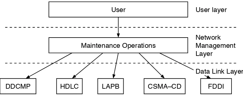
[image:17.612.97.499.539.702.2]the rest of the network architecture.
Figure 2: Simplified network model
User
Maintenance Operations
DDCMP
HDLC
CSMA–CD
FDDI
User layer
Network
Management
Layer
Data Link Layer
2.3 Low Level Maintenance Operation Model
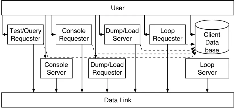
[image:18.612.77.494.180.373.2]The diagram in Figure 3 shows the components within the maintenance operation module.
Figure 3: MOP components
Requesters are the processes responsible for initiation of maintenance operations. This can be done either at higher level user request, or because of information obtained from a lower level. Requesters are the active side of a maintenance operation.
Servers are the processes that respond to maintenance requesters. They are the passive side
of a maintenance operation. Servers should not try to do more than they are capable of. For example, it is not acceptable to always volunteer to load every system that requests it and then take too long to get done because the local resources are overextended. The diagram shows servers and requesters as separate to represent their functional independence. In an imple
-mentation that supports multiple servers and/or requesters that use the same protocol type, they may have to be more closely coupled so that messages received through the data link are properly demultiplexed. Also, servers and requesters that allow multiple users must further demultiplex messages to the proper user processes.
The Client Data Base contains default information that the Dump/Load Server, Loop Re
-quester, Console Requester, and Test/Query Requester use tofill in necessary values in incom
-plete requests.
Lines to the top of processes indicate flow of the control data that initiates processing. Lines to the side indicate Network Management control. The dashed lines indicate data base access.
User
Data Link
Console
Server
Console
Requester
Dump/Load
Server
Loop
Requester
Loop
Server
Dump/Load
Requester
Client
Data
base
Test/Query
9
Chapter 3
Management
The operation of the Maintenance Operations components may be monitored and controlled using DNA Network Management. There is a single Module entity, called MOP. It has subor
[image:19.612.124.493.381.584.2]-dinate entities which define the database of MOP clients, and the Data Link circuits to be used. Figure 4 shows the complete entity structure of MOP.
Figure 4: MOP entity structure
3.1 Client subentity
The Client subentity is used to store default parameters for the Dump/Load Server, Console Requester, Loop Requester, and Test/Query requester. When a Load, Boot, Loop, Test, or Query directive is received, any required parameters not supplied with the directive are ob
-tained from the corresponding characteristics of a Client subentity, ifone is specified in the di
-rective. Similarly, when a request for Dump or Load service is received by the Dump/Load Server component from a Data Link, any parameters required to complete the request but not supplied in the received message are obtained from the characteristics of a Client subentity. In
MOP
Client
Circuit
this case, the Client subentity to be used is determined by the Circuit and (for LAN circuits) the Data Link source address or the Device Type from the received request message.
The set of Client subentities forms the “Client Database”. A lookup in this Database consists
of a search through the set of Client subentities for one that has the specified name, or the specified Circuit and (if applicable) LAN Address and/or Device Type. A LAN Address match takes precedence over a Device Type match; apart from that, the result of a search when more than one Client subentity matches the specified value is undefined.
3.2 Circuit subentity
The Circuit subentity describes a Data Link circuit to be used by MOP. For each defined Circuit subentity, MOP will use the specified Link Name attribute toopen a port in the appr
o-priate Data Link module. Thus, each Circuit subentity of MOP corresponds to a Data Link cir -cuit on which MOP services are available. Another Circuit characteristic defines which of the possible MOP services are enabled.
3.2.1 Operation subentity
The Operation subentity is created dynamically by the MOP components to allow manage
-ment toobserve the state of MOP operations that are in progress.
3.2.2 Station subentity
The Station subentity is created dynamically by the Configuration Monitor component, if
Configuration is set as one of the services enabled for a given circuit. This is applicable only to
LAN circuits. The Station subentity is created in response to a received System ID message, and records the information contained in that message.
Note that MOP does not relate the Station and Client subentities in any way. They serve unrelated purposes.
3.3 Support categories
In the description of attributes below, certain directive arguments and entity attributes are
flagged to indicate they are required only for some data links. Any arguments or attributes not
flagged are applicable regardless of data link type.
All directive arguments shall be accepted by all implementations; when an argument is not applicable, it is ignored. Implementations which do not support a particular data link type at all must still accept (and ignore) any arguments applicable to the unsupported data link.
Implementations which don’t support a particular data link type may omit any entity attrib
-utes applicable only to those data links. In that case, attempts to access these attributes are rejected (with the standard GetListError or SetListError CMIP error code).
In this version, the only defined support category is “LAN”, which indicates any Local Area Network data link, i.e., any of the IEEE 802 family data links, Ethernet, and FDDI.
3.4 Data type definitions
The following are the definitions for the management data types used in this chapter.
3.5
:
MOP M
o
dul
e
11
FROM Management IMPORT LANAddress; FROM Management IMPORT Octet;
SAPAddress = Octet; (* A more descriptive type name *)
StatType = (Off = 0, On = 1);
HelpType = (None = 0, Transmit = 1, Receive = 2, Full = 3);
OpType = (Loop Requester = 0, Console Requester = 1,
Console Carrier = 2, Load Requester = 3, Load Server = 4, Dump Requester = 5, Dump Server = 6, Configuration Monitor = 7,
Test Requester = 8, Query Requester = 9);
FunType = BIT SET OF OpType;
SIDFunType = BIT SET OF (Loop Server = 0, Dump Requester = 1,
Primary Loader = 2, Secondary Loader = 3, Boot = 4, Console Carrier = 5, Counters = 6);
DLErrType = (Wrong State = 0, Receive Error = 1,
Transmit Error = 2);
ServType = (Load = 0, Dump = 1, Loop = 2, Boot = 3,
Test = 4, Query = 5);
ProgType = (Secondary Loader = 0, Tertiary Loader = 1,
System = 2, Management = 3, CMIP Script = 4, Diagnostic = 5);
SvErrType = (No Resources = 0, Receive Error = 1,
Transmit Error = 2, File Open Error = 3, File I/O Error = 4, Operation Aborted = 5, Unknown Client = 6, Protocol Error = 7, Timeout = 8);
CircuitType = (CSMA–CD = 0, DDCMP = 1, FDDI = 2, HDLC = 3,
LAPB = 4, Token Ring = 5, Token Bus = 6, Z–LAN = 7); 1
DevType = (* Enumerated, refer to Appendix A.1 for code assignments. The name to be used for each code is the 3-character mnemonic shown there in the “Name” column *);
SoftwareID = String; (* Software ID is encoded as a text string. However, it must conform to the format restrictions documented in Section 5.5.1. If an invalid value of this data type is supplied to a directive, it is rejected with the standard CMIP error return Invalid Argument Value. *)
3.5 MOP Module
The MOP module is registered in the Distributed Systems Management Registry as shown below.
Class Name: MOP
Code: 16
Superior Class: Node
1 Note that these codes are not the same as the “Data Link Type” codes used in the System ID message, which are defined in Appendix A.2. To simplify the mapping between these two encodings, new values for Circuit Type and Data Link Type will be assigned such that the following algorithm applies:
IF DataLinkType " 10
3.5.1 Action Directives
The MOP module implements the usual directives Create, Delete, Enable, and Disable. In
addition, it implements five module-specific directives:Loop, Load, Boot, Test, and Query. If an
implementation does not support some of these functions, the corresponding directive is omitted and attempts to invoke it yield the standard Directive Not Supported exception.
3.5.1.1 MOP module specific action directives
In order to avoid awkward command language syntax, the five module-specific directives are not in fact directives of the module. This is because each directive must refer to a Circuit subentity (to identify the circuit to operate on) or a Client subentity (to refer to for directive parameters not explicitly specified in the directive)or both. Thus there are actually two sets of five directives, one associated with the Client subentity, one with the Circuit subentity. Seman
-tically these are equivalent, and the only difference in syntax is that one has an optional Circuit
argument and the other an optional Client argument. If the directive is issued to a Client
subentity, that subentity is in effect an implied argument of the directive; if the directive is is
-sued to a Circuit subentity, that subentity is in effect an implied argument.
In each of these five directives, each argument individually is optional but for any particular directive enough parameters must actually be supplied to allow the operation to be performed. One possibility is to supply all necessary parameters directly as directive arguments. The other possibility is to reference a Client subentity. In that case, the parameters are obtained from the Client characteristics, unless overridden by a corresponding argument.
For each of these five directives, refer to the description below for the list of parameters that is necessary tocomplete the function. If all of these are supplied as arguments, it is not neces
-sary to include a Client argument. Otherwise, the Client argument must be supplied. If no
matching Client subentity is found, the request is rejected (Unrecognized Client exception). Oth
-erwise, any parameters not supplied in the directive itself are obtained from the corresponding
characteristics of the Client subentity. After completion of this “merge”, all necessary parame
-ters must now be available; if not, the standard CMIP error Required Argument Omitted is re
-turned.
N
o
t
e:
Since these necessary parameters can be obtained either from the directive ar
-guments or from the Client database, it is not correct toconsider them “required arguments” in the sense that they are required to be present on the directive. In particular, as far as director processing is concerned, they have to be consid
-ered as optional arguments.
The Client subentity attribute Addresses is a Set data type. For the directives, an address can be explicitly supplied; if it is not, then the operation proceeds with each of the addresses in the Set, until a response is received (except in the case ofBoot, which simply loops through the
entire set since no response is expected). If the set is empty, the request is rejected (standard CMIP error Required Argument Omitted).
3.5.1.2 Create Directive
The Create directive creates the MOP entity. The Characteristics initially take their default values. The Modula-2+ description follows:
DIRECTIVE Create = 0 : Create; (* Create the MOP entity *)
REQUEST (* No input arguments *)
END;
3.5.1.3
:
D
e
l
e
t
e
Dir
ec
tiv
e
13
EXCEPTION Already Exists = 2 : (* MOP Module already exists *) END Already Exists;
END Create;
PROCEDURE Create ( )
RAISES {InsufficientResources}; (* CMIP common error *)
3.5.1.3 Delete Directive
The Delete directive deletes the MOP entity and reclaims any associated resources. The Modula-2+ description follows:
DIRECTIVE Delete = 1 : Delete; (* Delete the MOP entity *)
REQUEST (* No Input Arguments *)
END;
RESPONSE Success = 0 : (* No Output Arguments *) END Success;
EXCEPTION Has Children = 1 : (* Subentities must be deleted first *) END Has Children;
END Delete;
PROCEDURE Delete ( ) RAISES {};
3.5.1.4 Enable Directive
The Enable directive enables the MOP entity. The Modula-2+ description follows:
DIRECTIVE Enable = 2 : Enable; (* Enable the MOP entity function *)
REQUEST (* No input arguments *)
END;
RESPONSE Success = 0 : (* No Output Arguments *)
END Success; (* No Entity-specific Exceptions *)
END Enable;
PROCEDURE Enable ( ) RAISES {};
3.5.1.5 Disable Directive
The Disable directive disables the MOP entity. The Modula-2+ description follows:
DIRECTIVE Disable = 3 : Disable; (* Disable the MOP entity function *)
REQUEST (* No input arguments *)
END;
RESPONSE Success = 0 : (* No Output Arguments *)
END Success; (* No Entity-specific Exceptions *)
END Disable;
PROCEDURE Disable ( ) RAISES {};
3.5.2 Identifier Attribute
3.5.3 Characteristic Attributes
[image:24.612.68.486.192.300.2]The MOP module has the characteristic attributes shown in Table 1.
Table 1: MOP module characteristics attributes
3.5.4 Status Attributes
The MOP module has the status attributes shown in Table 2.
Table 2: MOP module status attributes
3.5.5 Counter Attributes
The MOP module does not have any counter attributes.
3.5.6 Event Reports
The MOP module does not generate any event reports.
3.6 Client subentity
The Client subentity is registered in the Distributed Systems Management Registry as shown below.
Class Name: Client
Code: 0
Superior Class: MOP
The Client subentity is used by the Load/Dump Server, Loop Requester, Console Requester, Test Requester, and Query Requester components of MOP. On systems where none of these are implemented, the Client subentity is omitted and any attempts to issue directives to it are re
-jected (with the standard No Such Entity exception).
Keyword Code Syntax Value Description
Version 0 VersionNumber V4.0.0 The version of the Maintenance Operations specification to which the implementation conforms. This attribute is read-only.
Supported
Functions 1 FunType [SystemSpecific] Specifies which MOP components are avail-able in this system. This can be used by the Director to avoid issuing directives that use omitted functions. This attribute is read-only.
Keyword Code Syntax Description
[image:24.612.71.458.409.445.2]3.6.1
:
Ac
ti
o
n Dir
ec
tiv
e
s
15
3.6.1 Action Directives
The Client subentity provides action directives for creating and deleting a subentity. These directives and the procedures they call are described below.
3.6.1.1 Create Directive
The Create directive creates a Client subentity with the specified identifier. The Character
-istics initially take their default values. The Modula-2+ description follows:
DIRECTIVE Create = 0 : Create; (* Create a new Client subentity *)
REQUEST (* No Input Arguments *)
END;
RESPONSE Success = 0 : (* No Output Arguments *) END Success;
EXCEPTION Already Exists = 2 : (* Client subentity already exists *) END Already Exists;
END Create;
PROCEDURE Create (Identifier: SimpleName)
RAISES {InsufficientResources}; (* CMIP common error *)
3.6.1.2 Delete Directive
The Delete directive deletes a Client subentity and reclaims any associated resources. The Modula-2+ description follows:
DIRECTIVE Delete = 1 : Delete; (* Delete an Client subentity *)
REQUEST (* No Input Arguments *)
END;
RESPONSE Success = 0 : (* No Output Arguments *)
END Success; (* No Entity-specific Exceptions *)
END Delete;
PROCEDURE Delete ( Identifier ) RAISES {};
3.6.1.3 Loop Directive
The Loop directive causes a loop test to be performed with another system.
DIRECTIVE Loop = 4 : Loop; (* Perform a Loop operation with another system *) REQUEST
ARGUMENT Circuit = 1 : SimpleName; ARGUMENT Address = 2 : LANAddress;
ARGUMENT Assistant System = 4 : SimpleName; ARGUMENT Assistant Address = 5 : LANAddress; ARGUMENT Assistance Type = 6 : HelpType; ARGUMENT Count = 7 : Integer;
ARGUMENT Length = 8 : Integer; ARGUMENT Format = 11 : Octet END;
RESPONSE Success = 0 : (* No output arguments *) END Success;
RESPONSE Invalid Response = 1 :
EXCEPTION Unrecognized Circuit = 1 : (* There is no circuit with the specified identification *) END Unrecognized Circuit;
EXCEPTION Data Link Error = 2 : (* An error was reported by the Data Link layer *) ARGUMENT Reason = 0 : DLErrType;
END Data Link Error;
EXCEPTION Unrecognized Assistant = 5 : (* No assistant with the specified identification *) END Unrecognized Assistant;
EXCEPTION Invalid Assistant = 6 : (* The Assistant Address is either a multicast address, or Assistant System was specified but the corresponding Client subentity has an empty Addresses list *)
END Invalid Assistant;
EXCEPTION Timeout = 7 : (* No response was received in the timeout period *) END Timeout;
END Loop;
PROCEDURE Loop (Client, Circuit, Address, AssistantSystem, AssistantAddress, AssistanceType, Count, Length, Format) RAISES {InvalidResponse,
InsufficientResources, (* CMIP common error *) UnrecognizedCircuit,
DataLinkError,
UnrecognizedClient, (* Does not apply here *) RequiredArgumentOmitted, (* CMIP common error *) UnrecognizedAssistant,
InvalidAssistant,
InvalidArgumentValue, (* CMIP common error *) Timeout};
For LAN circuits, if Assistance Type is None, the operation is a Loop-direct; If AssistanceType is some other value, the operation is Loop-assisted. For Loop-assisted, the de -fault assistant address is the Loop Assistant multicast address. A different address may be specified by including the Assistant Address parameter, which specifies the address directly, or
by specifying Assistant System, which specifies a name of a Client subentity. The Addresses characteristic of the named Client subentity is then used as the assistant address. On non
-LAN circuits, the Assistant Address, Assistant System, and Assistance Type arguments are ig
-nored.
The required parameters are:
• Circuit
• Address (for LAN circuits)
The defaults values for the optional parameters are:
• Assistance Type —None
• Assistant Address — Obtained dynamically: an assistant is found by sending a direct (non-assisted) Loop request to the Loop Assistance multicast address. If a response is received, the responding station is then used as the assistant for the rest of the opera
-tion.
3.6.1.4
:
L
o
ad Dir
ec
tiv
e
17
3.6.1.4 Load Directive
The Load directive causes a down line load to be performed to another system. A Boot is done first toforce the specified system to load.
DIRECTIVE Load = 5 : Load; (* Force load an adjacent system *) REQUEST
ARGUMENT Circuit = 1 : SimpleName; ARGUMENT Address = 2 : LANAddress; ARGUMENT System Image = 3 : FileSpec; ARGUMENT Script File = 4 : FileSpec;
ARGUMENT Secondary Loader = 5 : FileSpec; ARGUMENT Tertiary Loader = 6 : FileSpec; ARGUMENT Verification = 7 : OctetString; ARGUMENT Management Image = 8 : FileSpec; END;
RESPONSE Success = 0 : (* No Output Arguments *) END Success;
EXCEPTION Unrecognized Circuit = 1 : (* There is no circuit with the specified identification *) END Unrecognized Circuit;
EXCEPTION Data Link Error = 2 : (* An error was reported by the Data Link layer *) ARGUMENT Reason = 0 : DLErrType;
END Data Link Error;
EXCEPTION Protocol Error = 5; (* A protocol error occurred during the load *) END Protocol Error;
EXCEPTION Timeout = 7 : (* No response was received in the timeout period *) END Timeout;
END Load;
PROCEDURE Load (Client, Circuit, Address, SystemImage, ScriptFile, ManagementImage, SecondaryLoader, TertiaryLoader, Verification)
RAISES {InsufficientResources, (* CMIP common error *) UnrecognizedCircuit,
DataLinkError,
UnrecognizedClient, (* Does not apply here *) RequiredArgumentOmitted, (* CMIP common error *) ProtocolError,
InvalidArgumentValue, (* CMIP common error *) Timeout};
Required parameters are:
• Circuit
• Address (for LAN circuits) • System Image
• Script File (if requested by target system)
• Secondary Loader (if requested by target system) • Tertiary Loader (if requested by target system) • Management Image (if requested by target system) The default values for the optional parameters are:
3.6.1.5 Boot directive
The Boot directive causes a Boot message to be sent to another system.
DIRECTIVE Boot = 6 : Boot; (* Send a Boot trigger to an adjacent system *) REQUEST
ARGUMENT Circuit = 1 : SimpleName; ARGUMENT Address = 2 : LANAddress; ARGUMENT Verification = 7 : OctetString; ARGUMENT Device = 8 : String;
ARGUMENT Software ID = 9 : SoftwareID; ARGUMENT Script ID = 10 : SoftwareID; END;
RESPONSE Success = 0 : (* No Output Arguments *) END Success;
EXCEPTION Unrecognized Circuit = 1 : (* There is no circuit with the specified identification *) END Unrecognized Circuit;
EXCEPTION Data Link Error = 2 : (* An error was reported by the Data Link layer *) ARGUMENT Reason = 0 : DLErrType;
END Data Link Error; END Boot;
PROCEDURE Boot (Client, Circuit, Address, Verification, Device, SoftwareID, ScriptID) RAISES {InsufficientResources, (* CMIP common error *)
UnrecognizedCircuit, DataLinkError,
UnrecognizedClient, (* Does not apply here *) InvalidArgumentValue, (* CMIP common error *) RequiredArgumentOmitted}; (* CMIP common error *)
Required parameters are:
• Circuit
• Address (for LAN circuits)
The default values for the optional parameters are:
• Verification —%x0000000000000000
N
o
t
e:
The default value for the Verification parameter is a default only. It is not a “wild card” value. For any value of the Verification parameter including the de -fault value, the Console Server (target of the directive) will check the value and accept the operation only if the value matches the one expected.
3.6.1.6 Test Directive
The Test directive causes the IEEE 802.2 Test to be performed with another system. If ap
-plied to the wrong type of data link (i.e., non-LAN), the standard error Directive Not Supported is
returned.
DIRECTIVE Test = 7 : Test; (* Perform a Test operation with another system *) REQUEST
3.6.1.7
:
Qu
e
r
y
Dir
ec
tiv
e
19
ARGUMENT SAP = 10 : SAPAddress; ARGUMENT Format = 11 : Octet; END;
RESPONSE Success = 0 : (* No output arguments *) END Success;
RESPONSE Invalid Response = 1 :
ARGUMENT Count = 7 : Integer; (* Count of messages successfully looped *) END Invalid Response;
EXCEPTION Unrecognized Circuit = 1 : (* There is no circuit with the specified identification *) END Unrecognized Circuit;
EXCEPTION Data Link Error = 2 : (* An error was reported by the Data Link layer *) ARGUMENT Reason = 0 : DLErrType;
END Data Link Error;
EXCEPTION Timeout = 7 : (* No response was received in the timeout period *) END Timeout;
END Test;
PROCEDURE Test (Client, Circuit, Address, Count, Length, SAP, Format) RAISES {InvalidResponse,
InsufficientResources, (* CMIP common error *) UnrecognizedCircuit,
DataLinkError,
UnrecognizedClient, (* Does not apply here *) RequiredArgumentOmitted, (* CMIP common error *) DirectiveNotSupported (* CMIP common error *) InvalidArgumentValue, (* CMIP common error *) Timeout);
The required parameters are:
• Circuit
• Address
The defaults values for the optional parameters are:
• Count — 1 • Length — 40
• SAP — 0
• Format —%x55
3.6.1.7 Query Directive
The Query directive causes an IEEE 802.2 XID exchange to be performed with another sys
-tem. If applied to the wrong type of data link (i.e., non-LAN), the standard error Directive Not Supported is returned.
DIRECTIVE Query = 8 : Query; (* Perform an XID exchange with another system *) REQUEST
ARGUMENT Circuit = 1 : SimpleName; ARGUMENT Address = 2 : LANAddress; ARGUMENT SAP = 10 : SAPAddress; END;
RESPONSE Success = 0 :
ARGUMENT Window = 11 : Integer (* Window size for Type 2 LLC *) END Success;
RESPONSE Invalid Response = 1 : (* Protocol error in response *) END Invalid Response;
EXCEPTION Unrecognized Circuit = 1 : (* There is no circuit with the specified identification *) END Unrecognized Circuit;
EXCEPTION Data Link Error = 2 : (* An error was reported by the Data Link layer *) ARGUMENT Reason = 0 : DLErrType;
END Data Link Error;
EXCEPTION Timeout = 7 : (* No response was received in the timeout period *) END Timeout;
END Query;
PROCEDURE Query (Client, Circuit, Address, SAP, LLCTypes, Window) RAISES {InvalidResponse,
InsufficientResources, (* CMIP common error *) UnrecognizedCircuit,
DataLinkError,
UnrecognizedClient, (* Does not apply here *) RequiredArgumentOmitted, (* CMIP common error *) DirectiveNotSupported, (* CMIP common error *) InvalidArgumentValue, (* CMIP common error *) Timeout);
The required parameters are:
• Circuit
• Address
The defaults values for the optional parameters are:
• SAP — 0
3.6.2 Identifier Attribute
[image:30.612.75.489.544.600.2]The identifier attributes for each Client subentity are shown in Table 3.
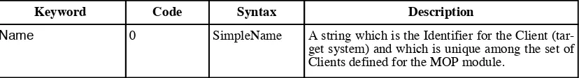
Table 3: Client entity identifier attribute
Code Syntax Description
Name 0 SimpleName A string which is the Identifier for the Client (tar-get system) and which is unique among the set of Clients defined for the MOP module.
3.6.3
:
Chara
c
t
e
risti
c
A
ttribut
e
s
21
3.6.3 Characteristic Attributes
[image:31.612.94.507.184.651.2]The characteristics attributes for each Client subentity are shown in Tables 4 and 5.
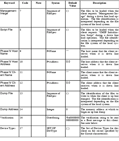
Table 4: Client entity characteristics attributes (part 1)
Keyword Code Syntax Default
Value Description
Note
Circuit 1 SimpleName “” The name of the Circuit subentity
(of the MOP module) that corre-sponds to the data link circuit to be used for communicating with this client.
Addresses 2 Set of
LANAddress {} The Set of LAN addresses for thisclient on the circuit specified by the Circuit characteristic. These addresses may not be multicast addresses (see note below). LAN
System Image 5 Sequence of
FileSpec ( ) The files to be loaded when theclient requests “Operating tem” (i.e., Program Type = Sys-tem Image, Software ID = Standard Operating System) dur-ing a down line load operation. The file identification is inter-preted depending on the file sys-tem of the local syssys-tem.
Secondary
Loader 3 Sequence ofFileSpec
( ) The files to be loaded when the client requests “Secondary Loader” during a down line load operation. The file identification is interpreted depending on the file system of the local system.
Tertiary
Loader 4 Sequence ofFileSpec
( ) The files to be loaded when the client requests “Tertiary Loader” during a down line load operation. The file identification is inter-preted depending on the file sys-tem of the local syssys-tem.
Diagnostic
Table 5: Client entity characteristics attributes (part 2)
N
o
t
e:
The address values in the Addresses parameters must be individual addresses,
not group (multicast) addresses. The length of the Verification attribute must be
"8. Attempts to set invalid values in these attribute are rejected with the CMIP
standard error Invalid Attribute Value.
Keyword Code Syntax Default
Value Description
Dump File 13 Sequence of
FileSpec ( ) The identification of the files towrite to when the client is up line dumped. The file identification is interpreted depending on the file system of the local system.
Note
Management
Image 7 Sequence of FileSpec
( ) The files to be loaded when the client requests “Management Im-age” during a down line load op-eration. The file identification is interpreted depending on the file system of the local system.
Script File 8 Sequence of
FileSpec
( ) The files to be loaded when the client requests “CMIP Initializa-tion Script” during a down line load operation. The file identifi-cation is interpreted depending on the file system of the local sys-tem.
Phase IV Host
Name 9 P4Name “” The host name that the client re-ceives when it is down line loaded.
Phase IV Host
Address 10 P4Address 0.0 The host address that the client re-ceives when it is down line loaded.
Phase IV
Cli-ent Name 11 P4Name “” The client name that the client re-ceives when it is down line loaded.
Phase IV
Cli-ent Address 12 P4Address 0.0 The client address that the clientreceives when it is down line loaded.
Dump Address 14 Integer 0 The memory address at which to
begin an up line dump
Verification 16 OctetString %x0000000
000000000 The verification string to be sentin a Boot message to this client. See note below.
Device Types 17 SET OF
3.6.4
:
Status
A
ttribut
e
s
23
3.6.4 Status Attributes
The Client subentity does not have any status attributes.
3.6.5 Counter Attributes
The Client subentity does not have any counter attributes.
3.6.6 Event Reports
The Client subentity does not generate any event reports.
3.7 Circuit subentity
The Circuit subentity is registered in the Distributed Systems Management Registry as shown below.
Class Name: Circuit
Code: 1
Superior Class: MOP
3.7.1 Action Directives
The Circuit subentity provides action directives for creating and deleting a subentity, and for enabling and disabling the various MOP functions. These directives and the procedures they
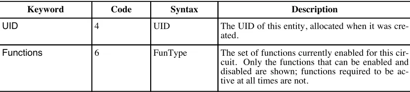
call are described below.
3.7.1.1 Create Directive
The Create directive creates a Circuit subentity with the specified identifier. The Character
-istics initially take their default values. The Modula-2+ description follows:
DIRECTIVE Create = 0 : Create; (* Create a new Circuit subentity *) REQUEST
ARGUMENT Type = 0 : CircuitType; END;
RESPONSE Success = 0 : (* No Output Arguments *) END Success;
EXCEPTION Unsupported Circuit Type = 1 : (* The specified Type argument value is not supported in this implementation *)
END Unsupported Circuit Type;
EXCEPTION Already Exists = 2 : (* Circuit subentity already exists *) END Already Exists;
END Create;
PROCEDURE Create (Identifier: SimpleName, Type: CircuitType) RAISES {InsufficientResources, (* CMIP common error *)
UnsupportedCircuitType};
3.7.1.2 Delete Directive
DIRECTIVE Delete = 1 : Delete; (* Delete an Circuit subentity *)
REQUEST (* No Input Arguments *)
END;
RESPONSE Success = 0 : (* No Output Arguments *)
END Success; (* No Entity-specific Exceptions *)
EXCEPTION Has Children = 1 : (* Subentities must be deleted first *) END Has Children;
END Delete;
PROCEDURE Delete ( Identifier ) RAISES {};
3.7.1.3 Enable Directive
The Enable directive enables a particular MOP function for the specified circuit. The fun
c-tion to be enabled is supplied as an argument. The Modula-2+ description follows:
DIRECTIVE Enable = 2 : Enable; (* Enable a Circuit subentity function *) REQUEST
ARGUMENT Functions = 0 : FunType; END;
RESPONSE Success = 0 : (* No Output Arguments *) END Success;
EXCEPTION Unsupported Function = 0 : (* The specified function is not supported, either not at all by the implementation, or not for this particular data link type. *)
END Unsupported Function;
EXCEPTION Nonexistent Data Link = 1 : (* The specified Data Link entity does not exist *) END Nonexistent Data Link;
EXCEPTION Open Port Failed = 2 : (* The Open Port operation failed *) END Open Port Failed;
END Enable;
PROCEDURE Enable (Function: FunType)
RAISES {Unsupported, NonexistentDataLink, OpenPortFailed};
3.7.1.4 Disable Directive
The Disable directive disables a particular MOP function for the specified circuit. The fun
c-tion to be disabled is supplied as an argument. The argument is optional; the default is to dis
-able all functions (i.e., all that are currently enabled). The Modula-2+ description follows:
DIRECTIVE Disable = 3 : Disable; (* Disable a Circuit subentity function *) REQUEST
ARGUMENT Functions = 0 : FunType;
DEFAULT = { Loop Requester, Console Requester, Console Carrier, Load Requester, Load Server, Dump Requester, Dump Server,
Configuration Monitor, Test Requester, Query Requester }
END;
RESPONSE Success = 0 : (* No Output Arguments *)
END Success; (* No Entity-specific Exceptions *)
END Disable;
3.7.1.5
:
L
oo
p Dir
ec
tiv
e
25
3.7.1.5 Loop Directive
The Loop directive causes a loop test to be performed with another system.
DIRECTIVE Loop = 4 : Loop; (* Perform a Loop operation with another system *) REQUEST
ARGUMENT Client = 0 : SimpleName; ARGUMENT Address = 2 : LANAddress;
ARGUMENT Assistant System = 4 : SimpleName; ARGUMENT Assistant Address = 5 : LANAddress; ARGUMENT Assistance Type = 6 : HelpType; ARGUMENT Count = 7 : Integer;
ARGUMENT Length = 8 : Integer; ARGUMENT Format = 11 : Octet END;
RESPONSE Success = 0 : (* No output arguments *) END Success;
RESPONSE Invalid Response = 1 :
ARGUMENT Count = 7 : Integer; (* Count of messages successfully looped *) END Invalid Response;
EXCEPTION Data Link Error = 2 : (* An error was reported by the Data Link layer *) ARGUMENT Reason = 0 : DLErrType;
END Data Link Error;
EXCEPTION Unrecognized Client = 3 : (* There is no client with the specified identification *) END Unrecognized Client;
EXCEPTION Unrecognized Assistant = 5 : (* No assistant with the specified identification *) END Unrecognized Assistant;
EXCEPTION Invalid Assistant = 6 : (* The Assistant Address is either a multicast address, or Assistant System was specified but the corresponding Client subentity has an empty Addresses list *)
END Invalid Assistant;
EXCEPTION Timeout = 7 : (* No response was received in the timeout period *) END Timeout;
END Loop;
PROCEDURE Loop (Client, Circuit, Address, AssistantSystem, AssistantAddress, AssistanceType, Count, Length, Format) RAISES {InvalidResponse,
InsufficientResources, (* CMIP common error *) UnrecognizedCircuit, (* Does not apply here *) DataLinkError,
UnrecognizedClient,
RequiredArgumentOmitted, (* CMIP common error *) UnrecognizedAssistant,
InvalidAssistant,
InvalidArgumentValue, (* CMIP common error *) Timeout};
For LAN circuits, if Assistance Type is None, the operation is a Loop-direct; If Assistance Type is some other value, the operation is Loop-assisted. For Loop-assisted, the default assis
-tant address is the Loop Assistant multicast address. A different address may be specified by including the Assistant Address parameter, which specifies the address directly, or by specifying Assistant System, which specifies a name of a Client subentity. The Addressescharacteristicof
the named Client subentity is then used as the assistant address. On non-LAN circuits, the
Assistant Address, Assistant System, and Assistance Type arguments are ignored.