J U L Y 1 9 8 9
WRL
Research Report 89/10
Integration and
Packaging Plateaus
of Processor Performance
research relevant to the design and application of high performance scientific computers. We test our ideas by designing, building, and using real systems. The systems we build are research prototypes; they are not intended to become products.
There is a second research laboratory located in Palo Alto, the Systems Research Cen-ter (SRC). Other Digital research groups are located in Paris (PRL) and in Cambridge, Massachusetts (CRL).
Our research is directed towards mainstream high-performance computer systems. Our prototypes are intended to foreshadow the future computing environments used by many Digital customers. The long-term goal of WRL is to aid and accelerate the development of high-performance uni- and multi-processors. The research projects within WRL will address various aspects of high-performance computing.
We believe that significant advances in computer systems do not come from any single technological advance. Technologies, both hardware and software, do not all advance at the same pace. System design is the art of composing systems which use each level of technology in an appropriate balance. A major advance in overall system performance will require reexamination of all aspects of the system.
We do work in the design, fabrication and packaging of hardware; language processing and scaling issues in system software design; and the exploration of new applications areas that are opening up with the advent of higher performance systems. Researchers at WRL cooperate closely and move freely among the various levels of system design. This allows us to explore a wide range of tradeoffs to meet system goals.
We publish the results of our work in a variety of journals, conferences, research reports, and technical notes. This document is a research report. Research reports are normally accounts of completed research and may include material from earlier technical notes. We use technical notes for rapid distribution of technical material; usually this represents research in progress.
Research reports and technical notes may be ordered from us. You may mail your order to:
Technical Report Distribution
DEC Western Research Laboratory, UCO-4 100 Hamilton Avenue
Palo Alto, California 94301 USA
Reports and notes may also be ordered by electronic mail. Use one of the following addresses:
Digital E-net: DECWRL::WRL-TECHREPORTS
DARPA Internet: [email protected]
CSnet: [email protected]
UUCP: decwrl!wrl-techreports
Integration and Packaging Plateaus
of Processor Performance
Norman P. Jouppi
Integration and packaging set limits to processor performance. This paper investigates the nature of these limits and their implications for computer ar-chitecture, organization, and design techniques.
This is a preprint of a paper that will be presented at the
International Conference of Computer Design,
IEEE, Cambridge, Massachusetts, October 2-4, 1989.
1. Introduction
Many papers have been written about limits to computer performance. Some of these have been based on quantum-mechanical [8], thermal [8], or size [10] limits. More recently circuit and system performance limits on VLSI interconnections and packaging have been investigated [1]. This work refines integration and packaging performance limits specifically in the context of computer systems. In particular, limits of computer performance under various packaging, architectural, organizational, and design techniques (e.g., gate-array vs. custom) are explored.
2. Is 3-Dimensional Packaging Needed?
There are four components to delay when driving a signal off a package. First, there is a fixed driver delay dependent on the chip’s technology for going off-chip. Second, once off-chip, there is also a delay proportional to the signal length traveled. This transmission delay is dependent on the voltage swings, transmission-line environment, and the actual distance traveled which is a function of the packaging technology. (These two delays are also present on-chip, but with smaller overall delay.) Third, there is a fixed receiver delay. Fourth, there is a delay due to clock skew between the transmitter and receiver. This can be a significant percentage of the total interconnection delay in high performance systems. In the remainder of the paper, interconnect delay will be used to describe the sum of these four components.
Since the interconnection delay has a term proportional to the distance traveled, the obser-vation has been made that the fastest computers would be limited by their size. One obvious limit is that the radius of the machine should be smaller than the distance traveled in a clock cycle by a signal at the speed of light. More specifically, if some portion of a machine must communicate with other parts of the machine in one cycle, the size of the machine is limited by the speed of transmission in the packaging media used in the machine. This has led to further observations that the maximum volume contained within a radius is a sphere, and that the fastest machines must be spheres. This puts a high premium on the development of 3-dimensional or "volumetric" packaging techniques.
liquid-based immersion cooling techniques [4], where components can be stacked together very closely.
In reality however, the need to make machines in the shape of spheres is only true if the machine consists of uniformly distributed interconnections between random points in the machine. This is not completely true for any machine, and is mostly untrue for most machines.
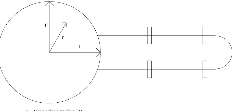
For example, consider a machine in the shape of a sphere. Imagine the machine is pipelined, and has independent functional units for floating-point operations. In this case machine perfor-mance would not be degraded if we "pulled" the floating-point pipeline out of the sphere (see Figure 1). This is because the data in a floating-point functional unit proceeds from pipestage to * pipestage without communicating with the rest of the machine except at its input and its output. Thus the machine is not limited to a sphere when the interconnections are structured and local instead of random.
r r r
[image:6.612.62.519.278.497.2]r = Clock time radius / 2
Figure 1: Machine structure vs. packaging required
Another important example of machine structure is provided by instruction and data caches. For caches of reasonable size, most instruction and data references are satisfied by the caches without recourse to main memory. Since cache misses are the infrequent case, access beyond the caches could be made to operate at a slower cycle time than the core of the machine without performance degradation. (Of course the overall access time and latency of the cache miss should still be minimized.) Similarly, if the CPU is entirely contained on a single chip (not including caches, floating-point, or MMU), many signal paths are entirely contained on the CPU chip. Some signal distribution frequencies based on the MultiTitan CPU chip [6] are given in
*We can clock the latches outside of the clock-time sphere in several ways. If the clock can be delayed with good
INTEGRATION ANDPACKAGINGPLATEAUS OFPROCESSORPERFORMANCE
Table 1. This shows the very strong tendency towards interconnection "locality of reference." In fact, this interconnection locality of reference is a corollary of Rent’s rule [9]. This is because as the number of gates on a chip increases, the percentage of nets that cross the chip boundary gets smaller and smaller. (This is also true for blocks within a chip.)
Total External Percent
Unit nets nets external
1 bit adder 41 13 31.7%
32-bit adder 1,120 106 9.5%
CPU datapath 11,263 148 1.3%
CPU + L1 ICache 62,745 136 0.2% Above + FPU + MMU 160,000+ 80 <0.05%
Table 1: Internal and external nets vs. integration
Thus, based on interconnection locality of reference and the structure inherent in computers, only a small portion of the machine is limited by speed of light considerations. Since signals travel at least 3in per nanosecond on most types of PC boards, this gives us a fair amount of room to work with. In particular, 3-D volumetric packaging techniques are unnecessary if the core of the machine fits within a circular instead of spherical clock-time radius, or if parts of the machine can extend beyond this radius.
Unfortunately this is not the whole story. If only 1% of the signals are not integrated into the core processor but they are on the critical path of the machine, the system performance will still be low. In particular, machines which contain no cache, such as Cray machines [2, 4], have problems in this respect. By not taking advantage of the locality of signal travel gained from the locality of data reference in a cache, main memory must be included in the core of the machine, greatly increasing the size of the core machine and the importance of advanced packaging tech-niques.
3. The Relative Importance of Signal Integration
At each level of integration the best performance is obtained by integrating critical paths of a machine onto the same chip. In addition, implementation of wide busses between functional units is simplified if both functional units reside on the same chip. Even if the best choices are made for the co-integration of circuits at a given density of integration, the delays in packaging will create limits to machine performance. Increased pipelining can partially compensate for packaging delays. For example, a pipestage could be added for each chip crossing, such that in the limit, the cycle time is equal to the maximum interconnection delay between chips. (In fact, the longest wires could be further pipelined by inserting additional latch chips, giving a cycle time closer to the average wire length.) But deeper pipelining also results in more cycles lost due to breaks in the pipeline as a result of branches and data dependencies. In the limit, the performance of the machine will be determined by the number of chip crossings required by the data and control (i.e., branch) dependencies present in a program.
[image:7.612.143.511.138.226.2]the pipeline characteristics specified in a configuration file. The programs simulated were our C compiler, PC board router, Linpack, the Livermore Loops, a timing verifier, the Hennessy Stan-ford benchmarks, whetstone, and the Unix Yacc program.
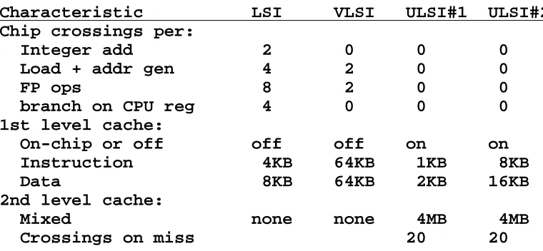
The latencies of functional units in a series of machines were estimated based on the number of chip crossings likely for each level of integration. Table 2 lists some assumptions for typical machines at each level of integration. For example, in an LSI environment a 32-bit adder might be contained on a single chip. But to use the results of an addition in another computation, we might have to leave the adder chip and go through a chip containing result forwarding (i.e., bypass) logic. Thus the total add delay in this technology involves crossing from the adder to the bypass back to the adder, for a total of two interconnection delays. In a VLSI single-chip CPU, the integer adder and bypass should be on the same chip. Since we are assuming gate delays are zero, the integer add delay on a VLSI chip is zero. However, the floating point unit might con-tain separate chips for addition/subtraction, multiplication, division, and floating-point registers and bypassing. Then two chip crossings would be required per floating-point operation. The only other chip crossings for a VLSI CPU without on-chip caches would be those to fetch in-structions or to fetch data during load inin-structions. Finally, consider an ULSI machine which has its first-level instruction and data caches on-chip along with the MMU and floating-point sup-port. It would only incur off-chip interconnection delays for cache misses. Two ULSI machines were considered, one with small on-chip caches and one with large on-chip caches.
Characteristic LSI VLSI ULSI#1 ULSI#2 Chip crossings per:
Integer add 2 0 0 0
Load + addr gen 4 2 0 0
FP ops 8 2 0 0
branch on CPU reg 4 0 0 0
1st level cache:
On-chip or off off off on on
Instruction 4KB 64KB 1KB 8KB
Data 8KB 64KB 2KB 16KB
2nd level cache:
Mixed none none 4MB 4MB
[image:8.612.94.474.350.526.2]Crossings on miss 20 20
Table 2: Model parameters for each level
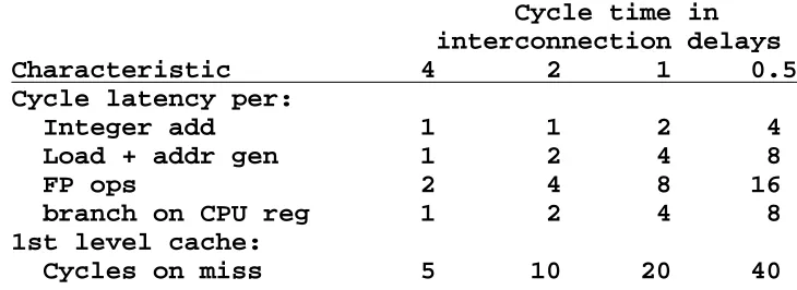
At each level of integration, a family of machines with different pipeline depths were simu-lated. For example, consider the pipelines possible with an LSI technology (see Table 3). The machine cycle time was varied between different multiples of the chip-to-chip interconnection delay. For example, a machine with a cycle time equal to a single chip crossing must have latches on each chip input pin. A machine pipelined this heavily will have many pipeline stages in technologies with low levels of integration. Similarly, a machine with a cycle time four times that of the interconnection delay has a relatively small number of pipeline stages even at lower levels of integration.
INTEGRATION ANDPACKAGINGPLATEAUS OFPROCESSORPERFORMANCE
Cycle time in interconnection delays
Characteristic 4 2 1 0.5
Cycle latency per:
Integer add 1 1 2 4
Load + addr gen 1 2 4 8
FP ops 2 4 8 16
branch on CPU reg 1 2 4 8
1st level cache:
[image:9.612.128.493.71.204.2]Cycles on miss 5 10 20 40
Table 3: Different pipelining possible in LSI
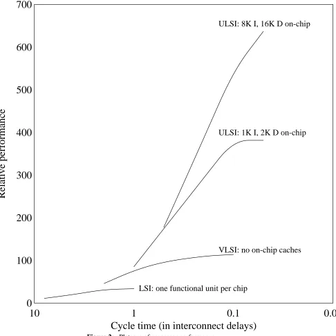
may be kept small, the extra pipestages that were added hurt performance because of data depen-dencies and their resulting breaks in the pipeline. Each curve for a given level of technology saturates when most of the performance is already being lost in pipeline breaks. This results in little or no additional performance when the number of pipestages is increased by decreasing the cycle time (i.e., for points on the curve farther to the right.) For a given cycle time (e.g., equal to one interconnect delay), the effects of increasing levels of integration can be seen by moving from a lower-integrated curve to a higher-integrated curve. Finally, if one interconnect delay (i.e., one on the lower axis) is taken to be 10ns, the relative performance figures correspond roughly to processor MIPS.
Packaging also affects the limit of machine performance. However, most packaging tech-nologies are only a second-order effect compared to the level of integration. This is because better packaging can reduce the component of interconnection delay due to wire length, but the packaging technology generally does not affect the fixed delay component due to the off-chip driver. (Certain wafer-scale integration technologies can reduce this in the limit, however.) Thus variation in packaging technology only allows system performance to vary from one plateau of performance to about the next or previous plateau, depending on whether it is better or worse than average packaging.
Note that the x-axis of Figure 2 is specified in units of interconnection delay. Thus systems with high performance signal transmission (e.g., unidirectional single-driver single-receiver ter-minated transmission lines) will have significantly higher performance plateaus than systems with poor signal transmission (e.g., multi-driver multi-receiver unterminated TTL traces).
10
1
0.1
0.01
Cycle time (in interconnect delays)
0
700
100
200
300
400
500
600
Relative performance
LSI: one functional unit per chip
[image:10.612.70.556.80.566.2]VLSI: no on-chip caches ULSI: 1K I, 2K D on-chip ULSI: 8K I, 16K D on-chip
Figure 2: Plateaus of processor performance
4. The Advent of Fully-Integrated Processors
The most interesting plateaus in Figure 2 are the top two. At these levels a CPU, FPU, MMU, instruction and data cache have all been integrated onto a single chip. These two plateaus are significantly higher than the others because at this level of integration most instructions can ex-ecute entirely on chip. Thus for most instructions, they are fully-integrated processors.
INTEGRATION ANDPACKAGINGPLATEAUS OFPROCESSORPERFORMANCE
with a 10ns clock cycle, while the on-chip clock period could be 2.5ns. If the 2.5ns internal clock is produced by frequency synthesis from the external 10ns clock via a phase-locked loop, no signals with fast edge rates or cycle times under 10ns need appear at the chip’s pins. This allows rather conventional packaging to be used compared to that required to support a machine built from many chips operating with 2.5ns chip crossings.
5. The New Technology Paradox
New technologies with very small gate delays are initially available only with relatively low levels of integration. As more and more circuits of a new technology are built, technology travels down an integration learning curve of increasing density. For example, the first available GaAs chips had significantly fewer gates per chip than CMOS or ECL chips in the same time frame.
Thus in order to exploit emerging technologies, advanced packaging technology must be used to partially ameliorate the effects of the lower density available in the emerging technology. For example, the Cray-3 needs to attain very dense packaging because its GaAs chips only contain 200-400 gates of logic [5]. Depending on the chip technology advantages and the packaging technology available, the overall system performance of a machine built with an emerging tech-nology at a low level of integration could still be less than that obtainable with a highly or fully-integrated version of the current mature technology. This discourages the widespread use of emerging technologies, and slows their progress along technology learning curves. An example of this is Josephson junction technology. Although IBM was able to built a prototype Josephson junction-based system in the late 1970’s with average gate delays of 44ps [3], the fastest overall cycle time for a system of four chips on two cards was 3.7ns [11]. This is a machine cycle time approaching 100 gate delays, which is far more than the 8 and 4 gate delays per cycle obtained in the Cray-1 and Cray-2 [4].
6. Conclusions
Integration and packaging set limits to processor performance. If cached-based architectures are used, only a relatively small core of a machine is limited by interconnection transmission delays. If large levels of integration are used to build cache-based machines, the need for volumetrically dense packaging is practically eliminated. Machines that contain a CPU, FPU, MMU, and instruction and data caches all on one die are fully-integrated processors from the standpoint of most instructions. Fully-integrated processors can have modest electrical signal I/O requirements because the frequency of signals crossing their pins can be several times less than that of the on-chip clock frequency. Finally, in order to exploit emerging technologies with-out high levels of integration, advanced volumetric packaging techniques will still be very im-portant.
7. Acknowledgements
References
[1] Bakoglu, Halil B.
Circuit and System Performance Limits on ULSI: Interconnections and Packaging.
PhD thesis, Stanford University, 1986.
[2] Cray Research Inc.
The CRAY-1 Computing System Reference Manual.
Chippewa Falls, WI, 1976.
[3] Gheewala, T.
Josephson-Logic Devices and Circuits.
IEEE Transactions on Electron Devices ED-27(10), Oct, 1980.
[4] Hockney, R. W., and Jesshope, C. R. The Cray X-MP and Cray-2.
Parallel Computers 2.
Adam Hilger, 1988, pages 146-155.
[5] Iverson, Wesley R.
It Looks Like an ’89 Debut for the Cray-3 After All.
Electronics , Dec, 1988.
[6] Jouppi, Norman P., Tang, Jeff, and Dion, Jeremy. A 20 MIPS Sustained 32b processor with 64b Data Bus.
In The International Solid State Circuits Conference, pages 7.5. IEEE, February, 1989.
[7] Jouppi, Norman P., Wall, David W.
Instruction-Level Parallelism for Superscalar and Superpipelined Machines.
In The Third Symposium on Architectural Support for Programming Languages and
Operating Systems, pages 272-282. IEEE, April, 1989.
[8] Keyes, Robert W.
Physical Limits in Digital Electronics.
Proceedings of the IEEE 63(5):740-797, May, 1975.
[9] Landman, B. S., and Russo, R. L.
On a pin versus block relationship for partitions of logic graphs.
IEEE Transactions on Computers C-20(12):1469-1479, Dec, 1971.
[10] Wilkes, Maurice V.
Keynote Address - Size, Power, and Speed.
In The 10th Annual Symposium on Computer Architecture, pages 2-4. IEEE Computer Society Press, May, 1983.
[11] Zappe, Hans H.
Josephson Computer Technology - An Overview.
INTEGRATION ANDPACKAGINGPLATEAUS OFPROCESSORPERFORMANCE
WRL Research Reports
‘‘Titan System Manual.’’ ‘‘MultiTitan: Four Architecture Papers.’’
Michael J. K. Nielsen. Norman P. Jouppi, Jeremy Dion, David Boggs, Mich-WRL Research Report 86/1, September 1986. ael J. K. Nielsen.
WRL Research Report 87/8, April 1988. ‘‘Global Register Allocation at Link Time.’’
David W. Wall. ‘‘Fast Printed Circuit Board Routing.’’ WRL Research Report 86/3, October 1986. Jeremy Dion.
WRL Research Report 88/1, March 1988. ‘‘Optimal Finned Heat Sinks.’’
William R. Hamburgen. ‘‘Compacting Garbage Collection with Ambiguous WRL Research Report 86/4, October 1986. Roots.’’
Joel F. Bartlett.
‘‘The Mahler Experience: Using an Intermediate WRL Research Report 88/2, February 1988. Language as the Machine Description.’’
David W. Wall and Michael L. Powell. ‘‘The Experimental Literature of The Internet: An WRL Research Report 87/1, August 1987. Annotated Bibliography.’’
Jeffrey C. Mogul.
‘‘The Packet Filter: An Efficient Mechanism for WRL Research Report 88/3, August 1988. User-level Network Code.’’
Jeffrey C. Mogul, Richard F. Rashid, Michael ‘‘Measured Capacity of an Ethernet: Myths and
J. Accetta. Reality.’’
WRL Research Report 87/2, November 1987. David R. Boggs, Jeffrey C. Mogul, Christopher A. Kent.
‘‘Fragmentation Considered Harmful.’’ WRL Research Report 88/4, September 1988. Christopher A. Kent, Jeffrey C. Mogul.
WRL Research Report 87/3, December 1987. ‘‘Visa Protocols for Controlling Inter-Organizational Datagram Flow: Extended Description.’’
‘‘Cache Coherence in Distributed Systems.’’ Deborah Estrin, Jeffrey C. Mogul, Gene Tsudik,
Christopher A. Kent. Kamaljit Anand.
WRL Research Report 87/4, December 1987. WRL Research Report 88/5, December 1988.
‘‘Register Windows vs. Register Allocation.’’ ‘‘SCHEME->C A Portable Scheme-to-C Compiler.’’
David W. Wall. Joel F. Bartlett.
WRL Research Report 87/5, December 1987. WRL Research Report 89/1, January 1989.
‘‘Editing Graphical Objects Using Procedural ‘‘Optimal Group Distribution in Carry-Skip
Representations.’’ Adders.’’
Paul J. Asente. Silvio Turrini.
WRL Research Report 87/6, November 1987. WRL Research Report 89/2, February 1989.
‘‘The USENET Cookbook: an Experiment in ‘‘Precise Robotic Paste Dot Dispensing.’’ Electronic Publication.’’ William R. Hamburgen.
Brian K. Reid. WRL Research Report 89/3, February 1989.
‘‘Simple and Flexible Datagram Access Controls for Unix-based Gateways.’’
Jeffrey C. Mogul.
WRL Research Report 89/4, March 1989.
‘‘Spritely NFS: Implementation and Performance of Cache-Consistency Protocols.’’
V. Srinivasan and Jeffrey C. Mogul. WRL Research Report 89/5, May 1989.
‘‘Available Instruction-Level Parallelism for Super-scalar and Superpipelined Machines.’’
Norman P. Jouppi and David W. Wall. WRL Research Report 89/7, July 1989.
‘‘A Unified Vector/Scalar Floating-Point Architecture.’’
Norman P. Jouppi, Jonathan Bertoni, and David W. Wall.
WRL Research Report 89/8, July 1989.
‘‘Architectural and Organizational Tradeoffs in the Design of the MultiTitan CPU.’’
Norman P. Jouppi.
WRL Research Report 89/9, July 1989.
‘‘Integration and Packaging Plateaus of Processor Performance.’’
Norman P. Jouppi.
WRL Research Report 89/10, July 1989.
‘‘A 20-MIPS Sustained 32-bit CMOS Microproces-sor with High Ratio of Sustained to Peak Performance.’’
Norman P. Jouppi and Jeffrey Y. F. Tang. WRL Research Report 89/11, July 1989.
‘‘Leaf: A Netlist to Layout Converter for ECL Gates.’’
INTEGRATION ANDPACKAGINGPLATEAUS OFPROCESSORPERFORMANCE
WRL Technical Notes
‘‘TCP/IP PrintServer: Print Server Protocol.’’ Brian K. Reid and Christopher A. Kent. WRL Technical Note TN-4, September 1988.
‘‘TCP/IP PrintServer: Server Architecture and Implementation.’’
Christopher A. Kent.
INTEGRATION ANDPACKAGINGPLATEAUS OFPROCESSORPERFORMANCE
Table of Contents
1. Introduction 1
2. Is 3-Dimensional Packaging Needed? 1
3. The Relative Importance of Signal Integration 3 4. The Advent of Fully-Integrated Processors 6
5. The New Technology Paradox 7
6. Conclusions 7
7. Acknowledgements 7
INTEGRATION ANDPACKAGINGPLATEAUS OFPROCESSORPERFORMANCE
List of Figures
INTEGRATION ANDPACKAGINGPLATEAUS OFPROCESSORPERFORMANCE
![Table 1. This shows the very strong tendency towards interconnection "locality of reference."In fact, this interconnection locality of reference is a corollary of Rent’s rule [9]](https://thumb-us.123doks.com/thumbv2/123dok_us/8996862.969354/7.612.143.511.138.226/tendency-interconnection-locality-reference-interconnection-locality-reference-corollary.webp)