© 2016, IRJET | Impact Factor value: 4.45 | ISO 9001:2008 Certified Journal
| Page 33
Image Inpainting Using Modified Exemplar- Based Method
Miss. S. C. Bhangale
1, Asst. Prof. P. R. Thorat
21
PG Scholar, S.P.W. E.C, Aurangabad,Maharashtra, India
2
Professor, E & TC Dept.,S.P.W. E.C, Aurangabad,Maharashtra,India
---***---Abstract -
- Inpainting refers to the art of restoring lostparts of image and reconstructing them based on the background information i.e. Image inpainting is the process of reconstructing lost or deteriorated parts of images using information from surrounding areas. The purpose of inpainting is to reconstruct missing regions in a visually plausible manner so that, it seems reasonable to the human eye. There have been several approaches proposed for the same. This paper introduce a new image inpainting approach which include salient structure completion and texture propogation.In salient structure completion step, incomplete salient structures are completed through content based image retrieval technique. In the texture propagation step first synthesizes texture information of completed salient structures. Then the texture information is propagated into remaining missing regions by patch based inpainting method.
Key Words: Exemplar, Image inpainting, Object removal,
Structure completion, Texture Synthesis, Patch Priority, Region filling
1.INTRODUCTION
Inpainting refers to the art of restoring lost parts of image and reconstructing them based on the background information. i.e. image inpainting is the process of reconstructing lost or deteriorated parts of images using information from surrounding areas. In fine art museums, inpainting of degraded painting is traditionally carried out by professional artists and usually very time consuming. The purpose of inpainting is to reconstruct missing regions in a visually plausible manner so that it seems reasonable to the human eye. There have been several approaches proposed for the same. It has made wide area in the field of image processing, such as computer graphics, image editing, film postproduction, image restoration.
1.1 Literature Review
Image inpainting has attracted a considerable amount of researches in recent years. The existing image inpainting approaches can be divided into following categories:
The first category is PDE based method this method attempt to fill the missing regions of an image
through a diffusion process which smoothly propagates information from boundary toward interior of the missing region. This diffusion process is simulated through solving a high order PDE [1],[3],[4]. These PDE based image inpainting techniques work at the pixel level, and perform well for small gaps. However, for larger missing regions or textured regions, the based methods cannot maintain texture details, which often lead to blurry artifacts.
The second category is exemplar-based texture synthesis method, which tries to fill the missing regions by Copying content from the existing part of the image. The exemplar-based method starting with the seminal work of texture synthesis of non-parametric matrix can be divided into two kinds, pixel level method [14] and patch level method [5],[7] The difference is whether the textures are Synthesized by one pixel or one patch at each step. Up to now, in the most famous exemplar- based inpainting method proposed by [7], the inpainting order is determined by the structure information of the image. Their insight is that the source region should be propagated along linear isophotes first, thus making the inpainting reasonable regardless of the boundary shape of the inpainting region. However, region filling and object removal by exemplar –based inpainting is limited to inpaint linear structures, often resulting in discontinuities of curving structures. However, a major drawback of these exemplar-based approaches stems from their greedy way of filling the image, which can often lead to visual inconsistencies. To overcome this deficiency, synthesizes image patches along user-specified curves in the unknown region using patches selected around the curves in the source region [15].Although this method achieves excellent results, it requires user manually to specify important missing structure information by extending a few curves or line segments from the known to the unknown regions[7]. In robust algorithm for exemplar based image inpainting the basic idea of method is that the order in which a pixel in the target region is filled was dictated by the level of “texturedness” of the pixel’s neighborhood. Although the intuition is sound, strong linear structures were often overruled by nearby noise, minimizing the value of the extra computation. A related technique drove the fill order by the local shape of the target region, but did not seek to explicitly propagate linear structures [6].
© 2016, IRJET | Impact Factor value: 4.45 | ISO 9001:2008 Certified Journal
| Page 34
and texture component. Then the combination methodtreats the structure and texture components with different methods. Simultaneous structure and texture image inpainting extend their PDE inpainting method [1] to texture and structure according to the decomposition described above. After that the structure component is inpainted by their PDE inpainting method. Texture component is inpainted by Criminisi method [7].
A more extensive structural and textural inpainting framework, in which the image is firstly, filtered using a curvature minimizing diffusion to generate structure component. Then, structure component is inpainted and segmented, and texture component is inpainted using the tree-based exemplar replication algorithm. These combination methods decompose or segment image into geometric features and texture. However, the image segmentation and decomposition is a challenge in image processing and the decomposition (segmentation) results are not often satisfactory [10].
1.2 SYSTEM OVERVIEW OF PROPOSED METHOD
Implementation of the proposed dissertation work shown in following fig.1
Fig-1: System Overview
A. Input Image
Input image is a photograph, natural image and synthetic image for processing that contain both colored, black and white images of different size etc. that is given to image inpainting.
B. Mask Image
Remove the unwanted object either single or multiple if required from the original image through paint called mask image or target which is to be inpainted. C. Incomplete Salient Structure Completion
Connecting incomplete salient structures is the key to obtain creditable inpainting results. However, simple connection or extension of the incomplete salient structures usually leads to negative results.
Inspired by CBIR technique color, texture features are used to determine the similarity of incomplete salient structures.
D. Texture Propagation of Completed Salient Structures After structure completion, we propagate texture information into the target region through patch based inpainting method (the patch size is 9x9 pixels). Fig.2 shows the flow chart of the inpainting process.
(a)First, given an input image, the user selects a target region, Ω, to be removed and filled. The source region, Φ, may be defined as the entire image minus the target region (Φ = I -Ω), as a dilated band around the target region, or it may be manually specified by the user. Following fig.3a and fig.3b shows terminology used in inpainting process and notation diagram respectively.
(b)Next, as with all exemplar-based texture synthesis, the size of the template window ψ must be specified. Here we provide a default window size of 9 x 9 pixels. Once these parameters are determined, the region-filling proceeds automatically. In this algorithm, each pixel maintains a color value (or “empty”, if the pixel is unfilled) and a confidence value, which reflects our confidence in the pixel value, and which is frozen once a pixel has been filled. During the course of the algorithm, patches along the fill front are also given a temporary priority value, which determines the order in which they are filled.
1. Computing patch priorities: In this algorithm performs the synthesis task through a best-first filling strategy that depends entirely on the priority values that are assigned to each patch on the fill front. The priority computation is biased toward those patches which: (i) Are on the continuation of strong edges and (ii) Are surrounded by high-confidence pixels. Given a patch ΨP centered at the point p for some p є δΩ ,
We define its priority p (p) as the product of two terms:
© 2016, IRJET | Impact Factor value: 4.45 | ISO 9001:2008 Certified Journal
| Page 35
…………... (2)
…………... (3) Where |ΨP | is the area of ΨP, n(P) is a unit vector
orthogonal to the front δΩ in the point p and ┴ denotes the orthogonal operator. The priority P (p) is computed for every border patch, with distinct patches for each pixel on the boundary of the target region.
Fig-2: Flow chart of the inpainting process .
During initialization, the function C (p) is set to
C (p) = 0,
= 1, ………….(4)
The confidence term C(p) may be thought of as a measure of the amount of reliable information surrounding the pixel p. The intention is to fill first those patches which have more of their pixels already filled, with additional preference given to pixels that were filled early on (or that were never part of the target region).
2. Propagating texture and structure information: Once all priorities on the fill front have been computed, the patch ΨP
with highest priority is found. We then fill it with data extracted from the source region Φ.
a b
Fig-3a): Terminology used in Inpainting Process 3b) Notation Diagram
In traditional inpainting techniques, pixel-value information is propagated via diffusion. As noted previously, diffusion necessarily leads to image smoothing, which results in blurry fill-in, especially of large regions. On the contrary, we propagate image texture by direct sampling of the source region. We search in the source region for that patch which is most similar ΨP to formally
………(6)
Where the distance d (ψa,ψb) between two generic patches
and ψa and ψb is simply defined as the sum of squared
differences (SSD) of the already filled pixels in the two patches.
Having found the source exemplar ψq, the value of
each pixel-to-be-filled p,’ |p’єψp∩Ω is copied from its
© 2016, IRJET | Impact Factor value: 4.45 | ISO 9001:2008 Certified Journal
| Page 36
This suffices to achieve the propagation of bothstructure and texture information from the source Φ to the target region Ω, one patch at a time. In fact, we note that any further manipulation of the pixel values (e.g., adding noise, smoothing etc.) that does not explicitly depend upon statistics of the source region, is more likely to degrade visual similarity between the filled region and the source region, than to improve it.
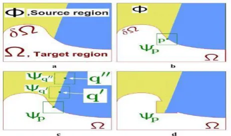
Fig-4: Structure propagation by exemplar-based texture synthesis
(a)Original image, with the target region Ω, its contour δΩ, and the source region (Φ) clearly marked.
(b)We want to synthesize the area delimited by the patch Ψp centered on the point p є δΩ.
(c)The most likely candidate matches for Ψp lie along the boundary between the two textures in the source region, e.g., Ψq’ and Ψq’’.
(d)The best matching patch in the candidates set has been copied into the position occupied by Ψp.
3. Updating confidence values: After the patch has been filled with new pixel values, the confidence C (p) is updated in the area delimited by as follows:
……….. (7)
This simple update rule allows us to measure the relative confidence of patches on the fill front, without image-specific parameters. As filling proceeds, confidence values decay, indicating that we are less sure of the color values of pixels near the centre of the target region.
We now focus on a single iteration of the algorithm to show how structure and texture are adequately handled by exemplar based synthesis. Suppose that the square template centered at the point p shown in figure 4.6(b), is to be filled. The best-match sample from the source region comes from the patch , which is most
similar to those parts that are already filled in Ψp .
In the example in figure 4.6(b), we see that if Ψp lies on the continuation of an image edge, the most likely best matches will lie along the same (or a similarly colored) edge (e.g.,
and in figure 4.6(c)). All that is required to propagate the isophotes inwards is a simple transfer of the pattern from the best-match source patch (figure4.5 (d)). Notice that isophotes orientation is automatically preserved. In the figure, despite the fact that the original edge is not orthogonal to the target contour δΩ, the propagated structure has maintained the same orientation as in the source region.
2. EXPERIMENTAL RESULT AND COMPARISON
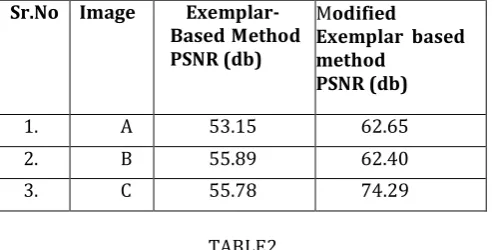
From figure 5.1, we use image (A) as color image and we remove the ball from the original image with object shown in figure (b).When we inpaint the image, figure (e) indicates the result of our method which gives better PSNR (62.65dB) than that of exemplar based method [figure.(d)] having PSNR (53.15 dB).The time required for both method is shown in table5.1. From figure (e), the result of proposed method is more accurate and less blur as compare to exemplar based method shown in figure(d).when we observed figure(e) the result of proposed method is more reasonable, natural and produce texture information well than those of exemplar based method shown in figure (d).From figure 5.1, we use image (B) as color image and we remove the man from the original image with object shown in figure (b).When we inpaint the image, figure (e) indicates the result of our method which gives better PSNR (62.40dB) than that of exemplar based method [figure.(d)] having PSNR (55.89 dB).The time required for both method is shown in table5.1. From figure (e), the result of proposed method is more accurate and less blur as compare to exemplar based method shown in figure(d).when we observed figure(e) the result of proposed method is more reasonable, natural andproduce texture information well than those of exemplar based method shown in figure (d).
[image:4.595.40.272.203.339.2]From figure 5.1, we use image (C) as color image and we remove the bottle from the original image with object shown in figure (b).When we inpaint the image, figure (e) indicates the result of our method which gives better PSNR (74.29dB) than that of exemplar based method [figure.(d)] having PSNR (55.78 dB).The time required for both method is shown in table 5.1. From figure (e), the result of proposed method is more accurate and less blur as compare to exemplar based method shown in figure(d).when we observed figure(e) the result
of
proposed method is more reasonable, natural and
produce texture information well than those of
exemplar based method shown in figure (d).
© 2016, IRJET | Impact Factor value: 4.45 | ISO 9001:2008 Certified Journal
| Page 37
method produced the linear structure and textureinformation more precisely.Graph 5.1 shows the result for the two different method.From figure5.1 it is evident that implemented series of algorithms provides better PSNR than exemplar based method From figure 5.1 it is also observed that the PSNR and time is depend on mask size. Change in mask size change the PSNR value and time.If the size of mask is less then we get better PSNR and less time for inpainting the image as compare to large mask size.
TABLE1
COMPARISON OF PSNR VALUE FOR EXEMPLAR – BASED METHOD AND PROPOSED METHOD ALGORITHMS.
Sr.No Image Exemplar- Based Method PSNR (db)
Modified
Exemplar based method
PSNR (db)
1. A 53.15 62.65
2. B 55.89 62.40
3. C 55.78 74.29
TABLE2
COMPARISON OF Time FOR EXEMPLAR –BASED METHOD AND PROPOSED METHOD ALGORITHMS.
Sr.No Image Exemplar- Based Method Time ( Sec)
Modified
Exemplar based method
Time ( Sec)
1. A 3.76 57.11
2. B 19.92 427.36
3. C 9.34 169.36
3. CONCLUSIONS
We have presented a novel inpainting method for removing objects from digital photographs.The result is an image in which the selected object has been replaced by a visually plausible background that mimics the appearance of the source region and produce more precise texture information. Our approach employs an modified exemplar based texture synthesis technique.
In this method, We have presented a novel inpainting technique based on automatic salient structure completion using content based image retrieval technique. The completed salient structures divide the target area into several sub-regions. Then, texture propagation is used to synthesize the texture information with samples from corresponding adjacent sub-regions.
In this paper we compares exemplar-based method and image inpainting modified exemplar based method interms of PSNR(dB).it is found that both technique work
noticeably well in removal of object from color, black and white images;but the image inpainting using modified exemplar based method we get better PSNR and little blurred in image than exemplar based technique and offers more precise texture information.
(a) ( b) ( c)
Image A
(d) (e)
(a) ( b) ( c)
Image B
(d) (e)
(a) ( b) ( c)
[image:5.595.40.288.262.387.2]Image C
(d) (e)
Figure 5.1 : Comparison for object removal from image A to C :
(a)The original image without object. (b)The original image with object (c)The mask image
© 2016, IRJET | Impact Factor value: 4.45 | ISO 9001:2008 Certified Journal
| Page 38
REFERENCES
[1] Bertalmio, M., Sapiro, G., Caselles, V., et al., 2000. Image inpainting. In: Proc.Computer Graphics (SIGGRAPH’00), Singapore, pp. 417–424.
[2] Bertalmio, M., Vesa, L., Sapiro, G., et al., 2003. Simultaneous structure and texture image inpainting. IEEE Trans. Image Process. 12 (8), 882–889.
[3] Chan, T.F., Shen, J., 2001. Non-texture inpainting by curvature driven diffusion. J. Vision Commun. Image Represent. 12 (4), 436–449.
[4] Chan, T.F., Shen, J., 2002. Mathematical models for local non-texture inpainting. SIAM J. Appl. Math. 62 (3), 1019– 1043.
[5] Rares A.Reinders M.J.T.and Biemond J. et al 2005, Image inpainting using feature based method. IEEE Trans .on image processing,14(10) ,1454-1468.
[6] Chen, J.Q., Pappas, T.N., Mojsilovic, A., et al., 2005. Adaptive perceptual color-texture image segmentation. IEEE Trans. Image Process. 14 (10), 1524–1536.
[7] Cheng, W. H., Hsieh, C.W., Lin, S.K., et al., 2005. Robust algorithm for exemplar based image inpainting. In: Proc. Internat. Conf. on Computer Graph.
[8] Criminisi, A., Perez, P., Toyama, K., 2004. Region filling and object removal by Exemplar-based inpainting. IEEE Trans. Image Process. 13 (9), 1200–1212.
[9] Dobrosotskaya, J.A., Bertozzi, A.L., 2008. A wavelet-laplace variational technique for image deconvolution and inpainting. IEEE Trans. Image Process. 17 (5), 657–663. [10] Efros, A.A., Leung, T.K., 1999. Texture synthesis by non- parametric sampling. In: Proc. Internat. Conf. on Computer Vision (ICCV’99), Kerkyra, pp. 1033–1038.ics, Imaging Vision, Beijing, pp. 64–69.
[11] Grossauer, H., 2004. A combined PDE and texture synthesis approach to inpainting”.In: Proc. European Conf. on Computer Vision, Slovansky ostrov, vol. 4, pp. 214–224. [12] Hays, J., Efros, A.A., 2008. Scene completion using millions of photographs. Commun. ACM 51 (10), 87–94. [13] Ignácio, U.A., Jung, C.R., 2007. Block-based image inpainting in the wavelet domain. Visual Comput. 23 (9–11), 733–741
[14] Komodakis, N., Tziritas, G., 2007. Image completion using efficient belief propagation via priority scheduling and pruning. IEEE Trans. Image Process. 16 (11), 2649–2661 [15] Li, H., Wang, S., Zhang, W., et al., 2010. Image inpainting based on scene transform and color transfer. Pattern Recognition Lett. 31 (7), 582–592.
[16] Sun, J., Yuan, L., Jia, J., et al., 2005. Image completion with structure propagation. ACM Trans. Graphics 24 (3), 861–868.
Wei, L.Y., Levoy, M., 2000. Fast texture synthesis using tree-structured vector quantization. In: Proc. Computer Graphics(SIG GRAPH’00),NewOrleapp.479–488