International Journal of Emerging Technology and Advanced Engineering
Website: www.ijetae.com (ISSN 2250-2459,ISO 9001:2008 Certified Journal, Volume 3, Issue 9, September 2013)
144
Modeling and Analysis of Monolithic Tri-Axial Ring Laser
Gyro
S. Naveen
1, A. Siva Rama Krishna
2, D. Kondayya
3, M. K. Gupta
4, K.Rambabu
51, 2, 3
Dept., of Mechanical Egg., Sreenidhi Institute of Science and Technology,Ghatkesar, Hyderabad -501301, A.P., India 4, 5Directorate of Laser Systems, RCI, Hyderabad-500069, A.P., India
Abstract - In air crafts, missiles and ships, during their motion, the sensors are prone to undergo lot of vibrations and shocks. Because of their sensitivity to these environments they malfunction. In order to avoid this situation all the sensors are modelled and analysed at the ground for different parameters viz. temperature, vibration and shock etc. A Ring Laser Gyro (RLG) is used for sensing the angle of rotation of missile. Hence application of the gyro in missile is very important and required to qualify against the stringent military specifications. This paper mainly covers the modelling and analysis of tri-axial ring laser gyro which consists of three gyros in a single block, called as monolithic block, with square resonator. The model will be analysed for its resonating frequency and correction of model is done respectively. The modelling of triaxial gyros is carried out using UNI-GRAPHICS and is analysed using ANSYS software package.
Keywords- Ring laser gyro Modeling, Model Analysis,
Frequency
I. INTRODUCTION
A gyro is an instrument, which senses inertial angular motion about itsinput axis without external reference.Over the five decades, a host of physical laws were utilized to develop operational gyros, which are currently in operation. Three most widely used principles on which successful gyro technologies are based can be described as follows:
1)Gyros based conservation of angular momentum of a
spinning rotor.
2)Gyro based on coriolies effect on a vibrating mass or structure.
3)Gyros based on saganc effect
This paper considers gyros based on saganc effect which tells about tri-axial block know as monolithic block with dither-rings. The ring laser gyro (RLG) is the outcome of extensive research for a solid-state gyro as an alternative to spinning rotor gyro technology, thus working of RLG was first demonstrated by Macek and Davies [1] in the year 1963 with a square cavity configuration with one meter (400 cm path length). From this large demonstration model, it took another 15 years for RLG to become operational for use in the strap down system configuration.
Further researches have been made to decrease its size and cost and increase performance and reliability. In the process of evolution, some of earlier designs and configuration of RLG become obsolete, such as the five sided gyro or the gyro with magnetic mirrors. The phenomenon of lock-in motivated scientists for its elimination by noval methods and these led to the evaluation of various operational designs such as mirror based RLG. The theoretical analysis of RLG deals with amplitudes and frequencies of the counter propagating laser waves using helium – neon (He-Ne) gas is used as an active medium in a ring laser gyro [2].
II. PRINCIPAL OF OPERATION
A certain rate of rotation of gyro induces a small difference between the time it takes light to traverse the ring in the two directions according to the Sagnac effect. This introduces a tiny separation between the frequencies of the counter-propagating beams, a motion of the standing wave pattern within the ring, and thus a beat pattern when those two beams are interfered outside the ring. Therefore the net shift of that interference pattern follows the rotation of the unit in the plane of the ring[4].RLGs, while more accurate than mechanical gyroscopes, and suffer from an effect known as "lock-in" at very slow rotation rates. When the ring laser is hardly rotating, the frequencies of the counter-propagating lasermodes become almost identical.
International Journal of Emerging Technology and Advanced Engineering
Website: www.ijetae.com (ISSN 2250-2459,ISO 9001:2008 Certified Journal, Volume 3, Issue 9, September 2013)
145 If a pure frequency oscillation is maintained, these small lock-in intervals can accumulate. This was remedied by introducing noise to the 400 Hz vibration.[3].Fig. 1 shows ring laser gyro.
Bracket plates (2 Nos)
Base plate
Dither rings (2 Nos)
Cathodes (2 Nos) Anodes
(6 Nos) Gyro block
[image:2.612.384.499.150.238.2]Mirrors(6 Nos)
Fig. 1: Ring laser gyro
III. MODELLING AND FINITE ELEMENT ANALYSIS
A three-dimensional model of the ring laser gyro developed using UNI-GRAPHICS software. A 10 nodes tetrahedral element was used for the solid mesh. Sensitivity analysis was performed to obtain the optimum element size. These analyses were performed iteratively at different element lengths until the solution obtained appropriate accuracy. Convergence of the stresses was observed, as the mesh size was successively refined. The element size of 0.20 mm was finally considered. A total of 213081 elements and 298472 nodes were generated with 5mm element length. Finite element analysis(FEA) [6] is widely used in the numerical
[image:2.612.94.254.197.358.2]Solution of many problems in engineering and technology. The problem include design of shafts, trusses, bridges, aero plane structures, buildings, heating and ventilation, fluid Flow, electric and magnetic fields, and so on. The main advantage of using finite element analysis is that many alternative designs can be tried out for their validity, safety, and integrity using the computer, even before the first prototype is built. Finite element analysis uses the idea of dividing a large body into small parts called elements, connected at predefined points called nodes. Element behavior is approximated in terms of the nodal variables called degrees of freedom. Elements are assembled with due consideration of loading and boundary conditions, this results in a finite number of equations. [5] Fig.2 shows finite element model.
Fig. 2: Finite Element Model of Gyro
IV. MODAL ANALYSIS
Modal analysis is usually used to determine the natural frequencies and mode shapes of component. It can be used as the starting point for the frequency response analysis. The finite element analysis codes usually used several mode extraction methods. The Lanczos [7] mode extraction method is used in this study. Lanczosis the recommended method for the medium to large models. In addition to its reliability and efficiency, the Lanczos method supports
sparse matrix methods that significantly increase
computational speed and reduce the storage space. This method also computes precisely the Eigen values and Eigen vectors. The number of modes was extracted and used to obtain the frequencies, which is the most important factor in this analysis. The model consists of the gyro, two dither rings, two cathodes, six anodes. The gyro, dither rings, two cathodes and six anodes is tightly meshed with hexahedral SOLID187 element. The mesh is generated using higher order tetra hydral element. The mode shapes and frequencies are listed Table 1.
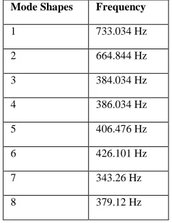
TABLE 1
MODE SHAPES AND FREQUENCIES
Mode Shapes Frequency
1 733.034 Hz 2 664.844 Hz 3 384.034 Hz 4 386.034 Hz 5 406.476 Hz 6 426.101 Hz
7 343.26 Hz
[image:2.612.381.507.533.696.2]International Journal of Emerging Technology and Advanced Engineering
Website: www.ijetae.com (ISSN 2250-2459,ISO 9001:2008 Certified Journal, Volume 3, Issue 9, September 2013)
146 The material properties used for ring laser gyro are listed below in the Table 2.
TABLE 2
MATERIAL PROPERTIES OF RLG
S.NO Material E (GPa) ν ρ (kg/m3)
1 Zerodur 90 0.24 2530 2 Be-Cu 115 0.30 8200 3 Al2014 73 0.357 8525 4 Kovar 207 0.317 0.302
E-Modulus of Elasticity; ν – Poisson’s ratio; ρ –density
V. RESULTS AND DISCUSSIONS
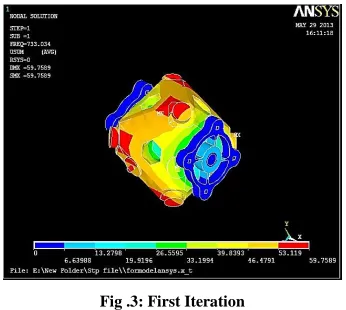
[image:3.612.344.538.133.289.2]The frequency to move ring laser gyro is analysed by using modal analysis using ansys software, the resonating frequency should be equal to 386Hz which is the natural frequency. The modelling of ring laser gyro is done using UNI-GRAPHICS software in which modal analysis is performed where the initial frequency is 733.034 Hz which is greater than the desired frequency and hence this is not suitable for resonating frequency. Fig.3 shows the first iteration value.
Fig .3: First Iteration
Second iteration is performed by making changes in the modelling i.e. increasing the inner and outer diameter of dither-ring. The frequency achieved is 664.844 Hz which is again greater than 400 Hz and hence cannot be considered. Fig. 4 shows the second iteration values.
Fig .4: Second Iteration
[image:3.612.356.526.371.664.2]Inner and Outer diameter of the dither ring has been increased to 5mm respectively using the UNI-GRAPHIC software dithered iteration has been performed. The frequency achieved is of the order of 384.034 Hz which is nearer to the desired frequency of the ring laser gyro. Fig.5 shows the third iteration value.
Fig. 5 Third Iteration
[image:3.612.82.255.421.576.2]International Journal of Emerging Technology and Advanced Engineering
Website: www.ijetae.com (ISSN 2250-2459,ISO 9001:2008 Certified Journal, Volume 3, Issue 9, September 2013)
[image:4.612.95.239.147.263.2]147
Fig. 7 Variation of Outer diameter vs. frequency
Fig. 6 and Fig. 7 shows the changes in the frequencies due to increase in inner and outer diameter of the dither-ring.
VI. THICKNESS OF THE DITHER-RING
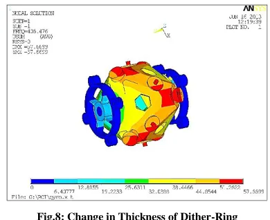
[image:4.612.69.264.412.571.2]When the thickness of the dither-ring is reduced by 1 mm the frequency obtained is 406.476 Hz. Since this is not nearer to natural frequency it cannot be considered as the resonating frequency. Fig. 8 shows the changes in the frequency due to thickness of the dither-ring
.
Fig.8: Change in Thickness of Dither-Ring
The thickness of the dither-ring is increased by 1mm, where the resultant frequency is 426.101 Hz which is greater than the desired frequency and is not acceptable. Fig.9 shows increase in frequency due to dither-ring.
Fig. 9: Increase in thickness in dither-ring
Fig. 10: Variation of thickness of dither ring
Fig. 10 shows the variation of thickness of the dither-ring. It is observed that frequency decreases with a decrease in thickness of the dither ring i.e. The frequency is directly proportional to the thickness of the dither ring. Hence by reducing the thickness of the dither ring to the tune of 8mm the desired frequency can be achieved. Hence
an optimum value of8mm thickness is considered and the
corresponding frequency obtained is 386.034Hz.
VII. SPOKE THICKNESS
International Journal of Emerging Technology and Advanced Engineering
Website: www.ijetae.com (ISSN 2250-2459,ISO 9001:2008 Certified Journal, Volume 3, Issue 9, September 2013)
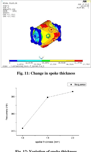
148 The modelling has been carried out using the Uni-Graphics for the same and the results are as below in fig. 11 and 12. From the graph it is observed that the change in frequencies is not linear. Though the desired frequency can be achieved by varying the thickness of the spokes, non-linearity in frequencies will pose a very tight tolerance in thickness variations. Considering the difficulty of manufacturing the criteria for optimizing the frequencies by optimizing the thickness of the spokes been discarded. Fig.11 shows the change in spoke thickness verses the frequencies.
[image:5.612.75.259.268.576.2]Fig. 11: Change in spoke thickness
Fig. 12: Variation of spoke thickness
Fig. 12 shows variations in spoke thickness and it is observed that there is a decrease in frequency due to decrease in spoke thickness.
VIII. CONCLUSIONS
CAD modelling of Ring laser gyro using UNI-GRAPHICS has been presented in this paper. Frequency of dither ring is analysed using a commercial code and ANSYS is also presented in this work. The analysis is performed by varying the diameter, spoke thickness and dither thickness. The results obtained shows the reduced frequency of ring laser gyro which is achieved by increasing the inner and outer diameter of dither-ring. The final optimal dimensions obtained through ANSYS are: inner and outer diameter of dither ring is 5mm, the spoke thickness is 1mm. Thickness of the dither ring is 1mm.
REFERENCES
[1] W.M. Macek, D.I.M. Davis, ‘Rotation Rate Sensing with a Travelling Wave Laser’, Appl. Phys Lett., 2 (1963), pp.67-9. [2] Amitava Bose, somnath puri, paritosh Banerjee, modern inertial
sensors and systems, 2009.
[3] K.U. Schreiber, A. Velikoseltsev, M. Rothacher, T. Klugel, G.E. Stedman, D.L. Wiltshire. Direct measurement of diurnal polar motion by ring laser gyroscopes. In Journal of Geophysical Research, 109 (B6): 2004. BibTeX.
[4] K.U. Schreiber, T. Klugel, G.E. Stedman. Earth tide and tilt detection by a ring laser gyroscope. In J. Geophys. Res, 108 2132, 2003. BibTeX.
[5] Tirupathi R. Chandrupatla, Finite Element Analysis for Engineering and Technology, University Press (India), 2004.
[6] Reddy, J.N., Introduction to the Finite Element Method with Engineering, McGraw-Hill Higher Education, 2004