International Journal of Emerging Technology and Advanced Engineering
Website: www.ijetae.com (ISSN 2250-2459, ISO 9001:2008 Certified Journal, Volume 7, Issue 9, September 2017)
148
Evaluation of Concrete Cover Distribution Pattern for RCC
Slab to Achieve Its Designed Requirements
M. M Sajidh
1, A. C. M Suhoothi
21Research Student (BEng (Hons) in Civil & Construction Engineering-London South Bank University) 2
Researcg Mentor (Academic Coordinator, Dept. of Civil Engineering British College of Applied Studies)
Abstract — the reinforcement bars in the RCC slabs are preserved from the environmental affects by providing the proper cover thickness. Mostly the cover thickness is designed properly according to the exposure condition but failed to provide as per the design requirements. This cover deviation can be due to poor workman ship and poor cover placing arrangement. In RCC elements cover deviation can be serious cause to the durability of the element. This requires a big attention on quality assurance to achieve the designed cover. As inspected in local sites, the concrete covers are not provided in an order or in a pattern, rather the covers are provided in points where the sagging of reinforcement bars can be observed. So cover placement pattern and spacing of cover in a two-way spanning slab which was designed according to BS 8110-1:1997 was analysed using the SAP 2000 software package. Two different types of cover distributions, Square and Diamond cover distribution patterns were analysed to identify the most efficient pattern in between those two patterns. This analysis showed that the diamond pattern is comparatively gives the most effective results than the square pattern. For different slab elements the spacing between covers of diamond pattern will vary according to the specification of the slab.
Keywords— Concrete cover, Cover deviation, Cover pattern, Cover spacing, Durability, SAP 2000
I. INTRODUCTION
In last few decades the Reinforced Cement Concrete (RCC) has become the widely used structural material in the construction industry. The RCC is a composite material which includes concrete (for compression) and reinforcement steel bars (for tension). The concrete is a proportional mix of cement, fine aggregate (sand), coarse aggregate (Stone) and water. The construction of RCC building is economic since all its ingredients can be found everywhere and easy of casting in any desired shapes. RCC is more durable comparing to other material and also it has a very low maintenance cost.
The reinforcement is mainly steel bars which is fulfilling the tensile character of concrete. Also the steel is bonding with the concrete well. To bear the tensile stress in a RCC element the reinforcing bars are placed at the bottom (for cantilever elements it is right opposite, i.e at the top) that is near to the face of element.
The exposure of the steel bars to the environment can cause serious problem on durability of the structure. It is very important to place the reinforcement bars at exact desired position with designed cover. The tying distance and the spacing of covers are two major influencing factors on cover deviation [1].
The biggest threat to the RCC structures is corrosion attack. Corrosion attack of reinforcement is very common effect in the RCC structures due to the poor arrangement of covers to the reinforcement [2] and improper selection of ingredients of concrete material (concrete mix and steel bar).
The reinforcement corrosion causes lots of problems in the structure. Some of the affects are load carrying capacity reduces, cracks (in slabs, beams and columns), concrete cover spalling of and etc. All these effects leads the structure to premature demolition or premature large repairs. So here the durability of structure reduces with the corrosion of reinforcement. It is very important to find out and control the factors that stimulate the corrosion attack on reinforcement bars.
This study assesses the most effective cover spacing and distribution pattern among square and diamond pattern cover distribution. This analysis is based on a two-way spanning slab with its length and width is 6.5m X 6.5m and designed according to BS 8110-1:1997.
International Journal of Emerging Technology and Advanced Engineering
Website: www.ijetae.com (ISSN 2250-2459, ISO 9001:2008 Certified Journal, Volume 7, Issue 9, September 2017)
149 II. LITERATURE REVIEW
A. Concrete Cover Deviation in Construction Stage
[image:2.612.325.563.233.407.2]The following research was done by Pawel Tworzewski, titled as ―Errors during Manufacturing of Reinforced Concrete Beams at the Example of Concrete Cover Deviations‖. The study was carried out to identify the impact of the workmanship to the cover thickness deviation. This is an experimental study that was done among 43 numbers of precast beam which are manufactured in a precast factory. After the concrete is hardened the beam is hammered at mid span to identify the placement variation of the deployed reinforcements.
Figure 1- An example of a hammered beam [2].
[image:2.612.64.265.289.383.2]After analyzing each of the cover deviations Δc. The results are plotted in histogram. The reduced cover is with negative sign and increased cover is with positive sign.
Figure 2- Concrete cover deviation [2].
1.Mostly the concrete beams are constructed without the desired reinforcement arrangement.
2.Deviation of reinforcement cover in top and bottom will seriously reduce the load carrying capacity. 3.In the case of side cover, if it increases the protection
of reinforcement to corrosion will be increased but in the case of reducing it will accelerate the corrosion, reduction in the cross section of reinforcement will cause failure in the structure.
B. Durability of Reinforced Concrete
This research paper is focused on durability of reinforced cement concrete with the concrete cover. Done by Chris Shaw in 2007 titled as ―Durability of Reinforced Concrete‖. Since the biggest problem of reinforced concrete is in placing the reinforcement in correct position. This paper covers how to meet the design requirements for durability.
Figure 3-Corrosion due to failure in achieving the designed cover [3].
To achieve the designed cover in situ concrete blocks, mortar blocks, piece of brick, piece of wood can be used. In some earlier literatures says that the rebars can be just placed on freshly poured concrete. For the buildings built earlier like before 1980s, the cover can be a big problem. To check the actual cover thickness cover meter can be used. For the places where reinforcing bars are congested the cover meter cannot be used. In that situation the radiography can be used. And also there is partial destructive method is there which is drilling the concrete and measuring the cover thickness.
For the buildings constructed between 1980 and 2000 the placement of reinforcement bars can be a problem. It means whether the cover is being used according to a proper code. But after the 2000s the British Standard 7973 is been used. That code refers to Specifications of spacers and chairs for reinforcement bars in concrete. Through this code the desired cover can be achieved.
[image:2.612.50.289.437.564.2]International Journal of Emerging Technology and Advanced Engineering
Website: www.ijetae.com (ISSN 2250-2459, ISO 9001:2008 Certified Journal, Volume 7, Issue 9, September 2017)
150 Reinforcement should be tied in exact positions to prevent the rebar from displacing from the designed position. The tying position and distances is referred from British Standard 7973.
The cover should be fixed to the links (that is the cover is including the link diameter also).
The British Standard 7973 is the major step achieved to ensure the cover is placed properly in the reinforced concrete. This is found to be most cost effective method in providing the cover. Eventually this makes sure the stability of the structure with strength and durability.
C. Cover Thickness Variation with Spacing and Tying Points of Cover
A research journal was done by A. P. MARAN, M. F. F. MENNA BARRETO, B. ROHDEN, D. C. C. DAL MOLIN and J. R. MASUERO. Titled as ―Assessment of cover to reinforcement in slabs using different spacer and tying distances‖. This paper expresses a broad description on the influence of cover spacing and tying distances on cover thickness deviation. This study is based on Brazilian standards. Aim of this study is to find out the cover deviation by controlling the above influencing factor of the reinforced concrete slabs. So the tying distance and the cover spacing are controlled to identify their influence on achieving the designed cover.
The porosity of the concrete playing a major role in protecting the rebars from corrosion, and the increment of cover thickness for rebar will delay the initiation of the corrosion. So when the designed cover is not achieved that would be one of the stimulating factor for premature deterioration of the reinforced concrete. The major influencing factors should therefore be carefully balanced. Similar to Euro code the Brazilian standard also recommend a tolerance value for cover in relevant exposure condition (For general condition it is 10mm and with high quality control it can reduced up to 5mm). In the Brazilian standards it is given the detail specifications only for the cover thickness but there is no references to refer for the tying distances of reinforcement and arrangement patterns for cover to achieve the intended cover thickness. But there are limits in execution of cover placing distance and it differs from the European standards, however, this maximum value of tying distance is varied among the type of structural element.
1. - Methodology: This study is carried out on cast in-situ concrete slabs in 1st and 2nd floors in a residential building in the city of Porto, Alegre in Brazil.
This exposure condition is classified as moderate aggressive condition. Studies shows that the diameter of the reinforcement bars effect the final cover. That is when the diameter is reduced, the cover thickness is also reducing. So the minimum diameter reinforcement bar has the critical condition. In the Brazilian standards the 5mm diameter bar is the minimum allowed size. So the slab with this diameter bar has been assessed on this study.
The assessed slab is 100mm thick with 20mm cover thickness. 5mm diameter bars laid across in 150mm spacing in both directions. Plastic type covers (type 16) and steel tying wires (1.65mm diameter) are used. Eight same type of slabs are taken within the first and the second floors. Since the reinforcement grid is placed within 150mm spacing, the reinforcement can be tied in every 150mm. So in one floor all the grid joint are tied, that is tying distance is 150mm. The covers are placed in 300mm, 450mm and 600mm spacing in three different slabs. And another slab panel is left alone without controlling any factors considered here. Similarly, in the other floor only the tying distance is changed to 300mm and the rest of the things are kept as same.
[image:3.612.374.516.505.656.2]2. - Controlling Factors: Tying distance and the cover spacing are the two controllable factors that are taken to account. As mentioned early in Brazilian standard maximum tying distance is defined, the allowed maximum tying distance is up to 350mm. So here the tying distance are within the allowable limit. The tying points and the cover positions are placed at the intersections.
International Journal of Emerging Technology and Advanced Engineering
Website: www.ijetae.com (ISSN 2250-2459, ISO 9001:2008 Certified Journal, Volume 7, Issue 9, September 2017)
[image:4.612.336.550.116.300.2]151 Figure 5-Cover placement at 450mm spacing and tying distance at
300mm [1]
[image:4.612.97.238.136.282.2]3. - Results and conclusion of the study: The results were found using Kolmogorev-Smirnov (KS) and Jarque-Bera (J-B) normality tests. It can be seen from the results that the dispersion of the cover deviation is not showing a big variation related to tying distances and the cover spacing. To check whether the considered factors has an influence on the cover deviation Analysis of variance was carried out to a significance level of 5%
Figure 6- Tying distances Vs Cover deviation [1].
Figure 6 shows that the 150mm tying distance gives a better results than 300mm tying distance. That is because when the reinforcement is tied closely, the net becomes stiffer
Figure 7- Cover distance Vs Cover deviation [1].
[image:4.612.63.272.331.588.2]The Figure 7 shows that when the cover is placed closely that gives the better results.
Figure 8- Combination of Cover spacing and Tying distance with cover deviation [1].
[image:4.612.333.554.335.521.2]International Journal of Emerging Technology and Advanced Engineering
Website: www.ijetae.com (ISSN 2250-2459, ISO 9001:2008 Certified Journal, Volume 7, Issue 9, September 2017)
152 III. METHODOLOGY
Here SAP2000 computer software was used to analyze. Different types of patterns were analysed to identify the most efficient and optimum cover placing pattern solution.
[image:5.612.100.240.236.347.2]Element detail: This is an edge panel of a first floor level slab which was designed for a hotel project in Bentota, Sri Lanka. The panel thickness is 200mm, width and length are 6.5m × 6.5m.
Figure 9- Slab panel (Thickness 200mm)
A. Reinforcement Detail
The edges one and four are discontinuous and edges two and three are continuous.
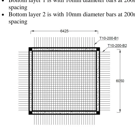
Bottom layer 1 is with 10mm diameter bars at 200mm spacing
[image:5.612.382.510.320.442.2] Bottom layer 2 is with 10mm diameter bars at 200mm spacing
Figure 10- Slab reinforcement arrangement
B. Behavior of Casted Concrete
At the beginning when the reinforcement bars are bound with aluminum wires, the reinforcement bars will sag at the mid span between covers only for the self-weight.
Normally in the construction sites the covers are used where the sagging is seen. But when concreting and after the concreting the cover can deviate to a considerable amount [2].
Soon after the concreting all the concrete loads will be transferred to the formwork directly. When the concrete starts setting, the load due to concrete above the reinforcement will be gradually transferred to the reinforcement bars. When the rebars start to take the loads, it will deform further more between the covers. In this instance the cover deviation may exceed the tolerance limit.
C. Load Distribution on Rebars
―It is assumed that the load above the reinforcement will be transferred as per the below diagram.‖
Figure 11-Load transferring pattern between rebars
Figure 12-Cross section of the slab
Self-weight of concrete = 23.6 kN/m3
Load acting on a rebar between two bonding
= 23.6 × 0.17 × 0.1 × 2
= 0.8 kN/m
Loads on rebar,
1. Self-weight of the reinforcement bar
2. Dead load of the concrete above the reinforcement
Load Combination,
Ultimate Limit State (ULS) design
[image:5.612.56.275.415.627.2]International Journal of Emerging Technology and Advanced Engineering
Website: www.ijetae.com (ISSN 2250-2459, ISO 9001:2008 Certified Journal, Volume 7, Issue 9, September 2017)
153 D. Defining the elements, loads and joint constraints in
SAP2000
In SAP2000 the reinforcement bars were drawn according to the designed specifications. All the support condition at the edges were set to be fixed supports. All the supports except the edge supports were set to be pin supports.
The reinforcement bars were defined as steel with below specification,
• 10mm bar diameter
• Elastic modulus 200 kN/mm2 • Solid circular shape
The reinforcement arrangement 200mm × 200mm grid spacing
As shown in Figure 3 the load of concrete will be distributed among all four bars. In a square shape arranged reinforcement bars, each side of the bar will take a distributed load and self-weight of the bar. The self-weight of the bar will be uniformly distributed to the bar and the concrete load will be distributed in a triangular shape which is maximum at the mid span (i.e. 0 at the edges and 0.8 kN/m at the mid span).Load combination was created for Ultimate Limit State design. That is with the extra concrete load and the self-weight of reinforcement.
E. Analysis in SAP 2000
The drawn reinforcement net was processed to check the deflection for ULS load combination to observe the maximum deflection.
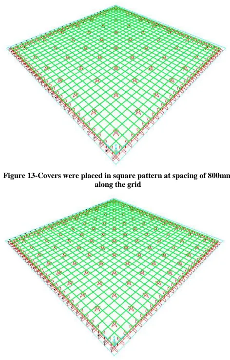
[image:6.612.323.559.137.506.2]1. - Square Patterned Cover Placement: Covers were placed in a square pattern. The cover spacing was set be 800 mm all four directions. This analysis was done in two different size of squares to identify deflection change with respect to scale reduction in square pattern.
Figure 13-Covers were placed in square pattern at spacing of 800mm along the grid
Figure 14-Covers were placed in square pattern at spacing of 600mm along the grid
International Journal of Emerging Technology and Advanced Engineering
Website: www.ijetae.com (ISSN 2250-2459, ISO 9001:2008 Certified Journal, Volume 7, Issue 9, September 2017)
[image:7.612.70.265.135.329.2]154 Figure 15-Covers were placed in diamond pattern at 1200mm spacing
[image:7.612.322.562.145.388.2]along the grid
Figure 16-Covers were placed in diamond pattern at 800mm spacing along the grid
IV. RESULTS
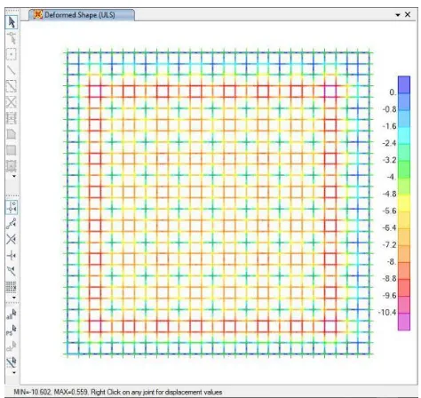
[image:7.612.71.268.363.562.2]A. Deflection in Square Pattern
Figure 17-Analysis of square pattern at 800mm spacing along the grid
Maximum deflection from square pattern with 800mm spacing along the grid was 36.4 mm (Figure 17).
[image:7.612.325.562.434.658.2]International Journal of Emerging Technology and Advanced Engineering
Website: www.ijetae.com (ISSN 2250-2459, ISO 9001:2008 Certified Journal, Volume 7, Issue 9, September 2017)
155 Maximum deflection from square pattern with 600 mm spacing along the grid was 10.6 mm (Figure 18).
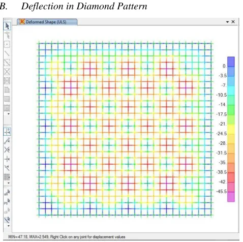
[image:8.612.49.288.162.400.2]B. Deflection in Diamond Pattern
Figure 19-Analysis of diamond pattern at 1200mm spacing along the grid
[image:8.612.328.558.338.516.2]Maximum deflection from diamond pattern with 1200mm cover spacing along the grid was 47.18 mm (Figure 19).
Figure 20-Analysis of diamond pattern at 800mm spacing along the grid
Maximum deflection from diamond pattern with 800
mm cover spacing along the grids was 9.23 mm (Figure 20).
TABLE I
RESULTING DEFLECTION FOR DIFFERENT COVER PLACING PATTERNS
Pattern type Cover spacing
along the grid
(mm)
Maximum
deflection
(mm)
Square
800
36.4
Square
600
10.6
Diamond
1200
47.18
Diamond
800
9.3
The Table II shows the change of deviation with respect to different patterns and spacing.
Figure 21-Cover deviation comparison between cover patterns and spacing.
V. CONCLUSION
When the scale of the pattern is reduced the cover deviation (deflection) was also minimized in both square and diamond patterns. Small scale reduction in the cover distance gives a large drop in cover deviation, it was changed from 36.4 mm to 10.6 mm for square pattern where it was changed from 47.18 mm to 9.3 mm for diamond pattern. As a consequence of higher reduction in the cover deviation in diamond pattern which is most effective in cover distribution than distributing it in square pattern.
[image:8.612.49.287.466.690.2]International Journal of Emerging Technology and Advanced Engineering
Website: www.ijetae.com (ISSN 2250-2459, ISO 9001:2008 Certified Journal, Volume 7, Issue 9, September 2017)
156 It can be considered as general case of quality controlling method to adopt the cover distribution in the intended slab. The cover deviation results found from SAP 2000 analysis, for the diamond pattern cover placement of 800 mm cover spacing along the grid, was found to be the lowest deflection value with 9.3mm. This deviation is within the allowable limit respect to the Euro code – 2.
Diamond pattern with 800 mm spacing along the grid gives an effective cover distribution, which is an affordable cover spacing with more than 2.5 feet and the adoption of this pattern provides less number of covers comparing to the square pattern with 600 mm cover spacing.
VI. SUGGESTIONS
The fire resistance hour will differ among the type of building and its functional requirements, it will result in the increment of the size of the cover. If the analysis was done for same type of building with different functional requirement the result would vary. So the analysis carried out here on this research and the obtained results are only applicable to the investigated slab sample. Similarly, the exposure condition of the structural element influence the cover design, the analysis results would also vary.
This study was carried out at the stage of hardening process, if this analysis can be developed after the hardening of concrete, it will give the deflection of reinforcement with the service effects.
In this research, the rigidity of the cover blocks were not considered, the rigidity of the cover affects the cover displacement while concreting process. By considering the rigidity of the cover block in to account the analysis can be developed further.
This study can be developed further with the experimental study.
REFERENCES
[1] A. P. MARAN, M. F. F. MENNA BARRETO, B. ROHDEN, D. C.
C. DAL MOLIN, J. R. MASUERO, 2015. Assessment of cover to reinforcement in slabs using different spacer and tying distances. Ibracon Structures and Materials Journal, 8(5), pp. 626-633. [2] Tworzewski, P., 2015. Errors during Manufacturing of Reinforced
Concrete Beams at the Example of Concrete Cover Deviations. Slovak Republic, University of Žilina.
[3] Shaw, C., 2007. Local Surveyors Direct. [Online] Available at: https://www.localsurveyorsdirect.co.uk/durability-reinforced-concrete [Accessed 20 3 2017].
[4] Di Qiao, Hikaru Nakamura, Khoa Kim Tran, Yoshihito Yamamoto, 2015. Experimental and analytical evaluation of concrete cover spalling behavior due to local corrosion. Journal of Structural Engineering, Volume 61A, pp. 2-3.
[5] Duinkherjav Yagaanbuyant , Javkhlan Bayar, 2011. The Influence of Concrete Cover to Protect Reinforcing Bar on Load Carrying Capacity of Floor Slab. Mongolia, Procedia Engineering.
[6] Laura Lemnitzer, Steffen Schröder, Alexander Lindorf, Manfred Curbach, 2009. Bond behaviour between reinforcing steel and concrete under multiaxial loading conditions in concrete containments. Espoo, Structural Mechanics in Reactor Technology. [7] N. Subramanian, K. Geetha, 1997. Concrete cover for durable
structure. The Indian Concrete journal, 71(4), pp. 1-5.
[8] Paul Oluwaseun Awoyera, Chinwuba Arum, Isaac Ibukun Akinwumi, 2014. Significance of Concrete Cover to Reinforcement in Structural Element at Varying Temperatures. International Journal of Scientific & Engineering Research, 5(6), pp. 1120-1123. [9] Sagiies, A. A., 1997. Carbonation in concrete and effect on steel
corrosion, Tampa Florida: College of Engineering University of South Florida.
![Figure 1- An example of a hammered beam [2].](https://thumb-us.123doks.com/thumbv2/123dok_us/8683050.875171/2.612.50.289.437.564/figure-an-example-of-a-hammered-beam.webp)
![Figure 4- Cover placement at 600mm spacing and tying distance at 150mm [1]](https://thumb-us.123doks.com/thumbv2/123dok_us/8683050.875171/3.612.374.516.505.656/figure-cover-placement-mm-spacing-tying-distance-mm.webp)
![Figure 6- Tying distances Vs Cover deviation [1].](https://thumb-us.123doks.com/thumbv2/123dok_us/8683050.875171/4.612.63.272.331.588/figure-tying-distances-vs-cover-deviation.webp)