International Journal of Emerging Technology and Advanced Engineering
Website: www.ijetae.com (ISSN 2250-2459,ISO 9001:2008 Certified Journal, Volume 4, Issue 7, July 2014)
Performance Analysis on FZPL Antenna‟s to Enhance Spatial
Resolution, Focusing Efficiency
.
P. Sankara Rao
Department of Electronics and Communication engineering, Sri Vasavi Institute Of Technology and Management, Nandamuru, Machilipatnam
Abstract-- In FZP’S Spatial resolution and focusing
efficiency play very important role for getting good results. There is dependency between resolution and FZP diameter. So I described analytical estimations on radius, diameter etc. This paper presents the dependency of focusing efficiency on (1st order diffraction wave) on number of zone plates,
dependency of focusing efficiency on interlayer distance(l) between zone plates , dependency of (rn) on number of zone
plates, dependency of (rn) on focal length(f), estimated values
of ‘Z’ and ‘l’. It also presents the spatial resolution improvement with the help of pinhole diffraction holography with the help of analytical estimations and graphs, also it describes the analytical estimations on radial distance to the different bright zones(r), width of the zone(w), interlayer distance between zone plates(l).
Keywords-- pinhole diffraction holography, multilayer zone
plates, interlayer distance, focusing efficiency, stacked multilevel Fresnel zone plate, FZPL antennas, FZPA, Fresnel-zone geometry, Spatial resolution.
I. INTRODUCTION
Now a day‟s Wireless communication becomes more popular and important in the communication field but due to some problems we cannot achieve the results up to our requirements, for example in RF Communication we are facing a lot of problems in getting full gain at receiver due to Knife –Edge Obstacles. In order to achieve good gain with improved efficiency I am describing the different methods and techniques.
FZP‟A are very important in getting high resolution especially in the field of X-ray[11] imaging and for analysis of materials, for this imaging purpose one eminent method is focused ion beam lithography process. In There are different methods for improving resolution and focusing efficiency by reducing side lobe levels, here I described one eminent method for improving resolution i.e
pinhole diffraction holography principles through
schematic diagram , analytical estimations, graphs, from diagram it is clear that there is exist a relation between pin hole diameter, distance between pin hole mask and image plane(Z), so this is clearly explained through necessary
formula 2d2/ λ, calculations based on this formula and
graphs.
Application Sub-wave length focal Distance is another application in improving characteristics of FZP‟s performance. Next aspect is to improve focusing efficiency by using “Stacked Multilevel FZPL Antennas” by implementing minimum possible interlayer distance between plates for enhanced efficiency. The FZPA with sub-wave length focus is an important aspect for future wireless applications [5][7]. we can achieve good
resolution, focusing efficiency, better radiation
characteristics by implementing MMW Binary photon-sieve concepts, Beam focusing methods, AHC FZPA concepts, pin hole diffraction holography principles.
It is very important to apply innovative methods for future wireless communications, some of future demands are 1)To apply innovative methods of implementing micro strip patch instead of using wave guide as a feed element to the Low-Profile FZPA since it becomes ideal. 2) To Enhance the aperture efficiency by adopting innovative methods, since it is small.3) To Provide phase correction method without increasing the thickness, complexity, cost of the antenna.
So it is very important to improve efficiency of FZPL
lens antennas by improving radiation pattern
characteristics, side lobe reduction[10], resolution, focusing efficiency aperture efficiency etc. These are possible to achieve by implementing innovative methods.
In addition to the above it is also essential to minimizing the Diffraction losses and improves Gain by minimizing the effects of Knife-Edge Obstacles ,improving Field strength, radiation pattern characteristics, resolution, efficiency[4][6] of FZPL antennas with the help of Fresnel-Zone geometry and /approximate evaluation of the contribution of individual Fresnel- Zones to the total field, leads to the Fresnel theorem: the total field is just one-half that due to the first zone alone.
II. DESIGN EQUATION OF AFRESNEL ZONE
Let [4]
rn=radial distance to the nth zone,
International Journal of Emerging Technology and Advanced Engineering
Website: www.ijetae.com (ISSN 2250-2459,ISO 9001:2008 Certified Journal, Volume 4, Issue 7, July 2014)
rn2 =nf λ+n2 λ2/4---(1)
The radius of(rn) of nth
The radius of(rn) of nth maximum or minimum can be
found from width of the zone
(w)=f λ/2 rn--- (2)
A. Dependency of (rn ) on focal length(f)
Estimating the width of zone based on f, λ ,rn
Zone number(n) =1, wave length(λ)=0.1nm (0.001(µm)
Table I
0 100 200 300 400 500
focal length(f)
λ=0.1
radius(rn)
variation of radius(rn) with focal length(f)
[image:2.612.49.562.100.607.2]focal length(f) in micrometers radius of n th zone(rn)
Fig-1 Variation of radius(rn) with focal length(f) a) wave length λ=0.1, zone number(n=1), b) wave length λ=0.2, zone number (n=1),
From (Fig-1) this analysis we observed that if radius
increases with increase in focal length. (if f increases rn
increases)
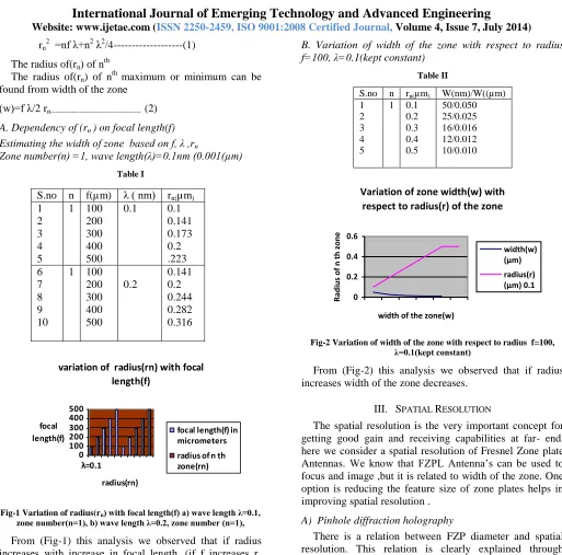
B. Variation of width of the zone with respect to radius f=100, λ=0.1(kept constant)
Table II
S.no n rn(µm) W(nm)/W((µm)
1 2 3 4 5
1 0.1 0.2 0.3 0.4 0.5
50/0.050 25/0.025 16/0.016 12/0.012 10/0.010
Variation of zone width(w) with respect to radius(r) of the zone
0 0.2 0.4 0.6
width of the zone(w)
R
adi
us
of
n
th z
one
width(w) (µm) radius(r) (µm) 0.1
Fig-2 Variation of width of the zone with respect to radius f=100, λ=0.1(kept constant)
From (Fig-2) this analysis we observed that if radius increases width of the zone decreases.
III. SPATIAL RESOLUTION
The spatial resolution is the very important concept for getting good gain and receiving capabilities at far- end, here we consider a spatial resolution of Fresnel Zone plate Antennas. We know that FZPL Antenna‟s can be used to focus and image ,but it is related to width of the zone. One option is reducing the feature size of zone plates helps in improving spatial resolution .
A) Pinhole diffraction holography
There is a relation between FZP diameter and spatial resolution. This relation is clearly explained through pinhole diffraction holography method. In this method of pin hole diffraction holography distance between pin hole mask and image plane (Z)is very important criteria. In this concept I calculated estimated Z values through appropriate analysis.
S.no n f(µm) λ ( nm) rn(µm)
1 2 3 4 5
1 100 200 300 400 500
0.1 0.1
0.141 0.173 0.2 .223 6
7 8 9 10
1 100 200 300 400 500
0.2
[image:2.612.77.236.268.411.2]International Journal of Emerging Technology and Advanced Engineering
Website: www.ijetae.com (ISSN 2250-2459,ISO 9001:2008 Certified Journal, Volume 4, Issue 7, July 2014)
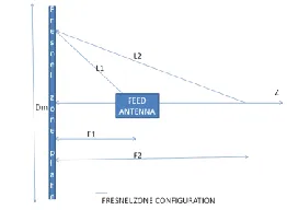
Let Δ rn = (outer most zone width) width of the zone,
N= Total number of zones=pinhole diameter= illumination wave length, z=distance between pinhole and the image
plane. condition for estimating „z‟ value Z > 2d2/ λ First
we have to calculate 2d2/ λ then we can estimate the value
of „z‟. here we note that distance between pinhole and image plane=focal length.
In this analysis I kept λ=0.1nm(kept constant)for different pin hole diameter(d). Here I consider three cases 1) λ=0.1nm 2) λ=0.2nm 3) λ=0.3nm
ESTIMATING' Z' VALUE
0 500 1000 1500 2000
PIN HOLE DIAMETER(d) in µm
e
st
im
at
e
d'
Z'
V
A
LU
E
(Z)
in µm
pin hole diameter (d) in um
[image:3.612.372.503.187.283.2]Estimate d z value(z) in mvalue(z
[image:3.612.43.284.253.728.2]Fig-3 a
Table III
s.no d(nm) d(µm) λ(nm) 2d2/λ( µm)
Estimated „Z‟ value( µm) 1
2 3 4
500 100 200 300
0.05 0.1 0.2 0.3
0.1
50 200 800 1800
<50 <200 <800 <1800 5
6 7 8
50 100 200 300
0.05 0.1 0.2 0.3
0.2
25 100 400 900
<25 <100 <400 <900 9
10 11 12
50 100 200 300
0.05 0.1 0.2 0.3
0.3
16.650 66.6 266.4 599.4
<16.65 <66.6 <266.4 <599.44
From this (graph-3)table we observed that if „d‟ value increases estimated „Z‟ value also increases which causes decrease in efficiency. So we should maintain minimum
possible pin hole diameter to get good efficiency.
Fig-3 b Pin hole diffraction holography principle
IV. FOCUSING EFFICIENCY
In FZPL Antenna‟s focusing efficiency is very crucial thing , so it is very much important to improve .To improve focusing efficiency we have to adopt a new concept called “Stacked Multilevel FZP”, In which we consider multiple of layers by using this we can enhance the focusing efficiency.
EZP have been used as focusing elements in hard X-ray. High efficiency [10]can be achieved by using binary zone plates and by using multilevel zone plate with zone plate stacking. Here we consider each couple of zones of bi-level FZP has been replaced by M zones with phase –shift growing by (2П/M) at each subsequent zone[12]. Focusing efficiency can be increased with increase in number of zone plates. It is represented by analytical estimations as shown in tabular form
Let M= number of zones, 2π/M = phase shift
By using this data we can calculate first order diffraction
wave(η1), first order diffraction wave (η1)=sin(2π/M)/
(π/M)2
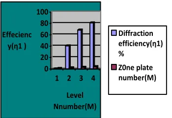
A.Dependency of focusing efficiency(η1) on number of zone plates(M)
Table IV
S.NO M Phase shift η1 %
1 1 3600 0
2 2 1800 40.56
3 3 1200 68.4
[image:3.612.42.284.271.721.2]International Journal of Emerging Technology and Advanced Engineering
Website: www.ijetae.com (ISSN 2250-2459,ISO 9001:2008 Certified Journal, Volume 4, Issue 7, July 2014)
0 20 40 60 80 100
Effecienc y(η1 )
1 2 3 4
Level Nnumber(M)
Variation of first order diffraction efficiency(η1) with Level number(M)
Diffraction efficiency(η1) %
Z0ne plate number(M)
Fig-4Variation of first order diffraction efficiency(η1) with Level number(M)
From(Fig-4 )observed that efficiency increases with increase in number of zone plates. In this case efficiency also depends on phase shift.
[image:4.612.347.541.134.266.2]B. Dependency of focusing efficiency(η1) on interlayer distance between zone plates(l)
Table V
S.NO F(m) N F/6N( µ
m)
Estimated „l‟ value
1 1 100
200
300
400
500 1660
833
555
416
330
<1660
<833
<555
<416
<330
2 2 100
200
300
400
500 3330
1660
1110
833
666
<3330
<1660
<1110
<833
<666
3 3 100
200
300
400
500 5000
20000
1660
1250
1000
<5000
<20000
<1660
<1250
<1000
0 200 400 600 800 1000 1200 1400 1600 1800
Estimated (l) value
f=1 300 500
Number of zone rings(n)
Estimation of Interlayer distance(l) between zone plates with respect to zone rings(N)
number of zone plates
[image:4.612.85.260.182.302.2]interlay distance(l) I micro met
Fig-5 Estimation of Interlayer distance(l) between zone plates with respect to zone rings(N)
From this (graph-5) We observed that if number of zone rings increases estimated interlayer distance between zone plates increases which leads in decrease in efficiency. So We should maintain minimum interlayer distance between zone plates.
V. CONCLUSION
Now a days, an increasing demand of Wireless and mobile communications which requires high quality of transmission with less price, high speed. Efficiency and resolution of any system plays vital role in communication so it is very important to develop by implementing new methods. This paper gives some analytical concepts and analysis for increasing focusing efficiency and resolution.
In this paper I described through numerical
[image:4.612.71.267.413.699.2]International Journal of Emerging Technology and Advanced Engineering
Website: www.ijetae.com (ISSN 2250-2459,ISO 9001:2008 Certified Journal, Volume 4, Issue 7, July 2014)
Acknowledgement
My grateful thanks to my guide Dr. Padmapriya, Associate Professor, ECE dept, JNTUK, A.P. For her constant guide lines and encouragement as per my requirements.
REFERENCES
[1] Minin. Minin. Diffractive Quasioptics and its Applications
Novosibirsk: SibAGS, 1999. 307p. (in Russian).
[2] “Millimeter- Wave Fresnel-Zone, Plate Lens and Antenna”, Hristo
D. Hristov, Senior Member, IEEE, and Mathieu H. A. J. Herben,
Senior Member, IEEE
[3] “Millimeter Wave FresnelZone Plate Lens and Antenna”, Hristov,
H.D., and Herben, M.H.A.J., IEEE Trans. Microw. Theory and Tech, 1995, 43 (12), pp.27792785.
[4] Minin, I.V., Minin, O.V., Gagnon, N., Petosa, A., “Investigation of
the Resolution of Phase, Correcting Lenses with Small Focal
LengthtoDiameter, Ratios and Subwavelength Focus”,
Electromagnetic Theory Symposium (EMTS) 2007, July 2628, 2007, Ottawa, On, Canada.
[5] A New Fresnel Zone Antenna with beam Focused in the Fresnel
Region, Shaya Karimkashi and Ahmed A. Kishk, Dept. of Electrical Engineering, University of Mississippi, University, MS, 38677, USA.
[6] Y.J.Guo, S.K.Barton. Fresnel Zone Antennas. Kluwer Academic
Publishers, 2002.
[7] L. J. Cutrona, E. N Leith, L. J. Porcello, W. E. Vivian On the
Application of Coherent
[8] Optical Processing Techniques to Synthetic-Aperture Radar Proc.
IEEE,. 54, pp. 10261032
[9] R. K. Moore, J. W. Rouse. Electronic Processing for Synthetic
Aperture Array
[10] pp. 969971.9. Minin, Minin. Array of Fresnel Zone Plate Lens
Antennas: Circular, Hexagonal with Chiral
[11] Symmetry and Hexagonal Boundary Digest of the Joint 31st
International Conference on
[12] Infrared and Millimeter Waves and 14th International Conference on