International Journal of Emerging Technology and Advanced Engineering
Website: www.ijetae.com (ISSN 2250-2459,ISO 9001:2008 Certified Journal, Volume 4, Issue 8, August 2014)
412
PID-MPC Based Automatic Voltage Regulator Design
in Wide-Area Interconnect Power System
Qing Liu
1, Tarek Hassan Mohamed
2, Thongchart Kerdphol
3, Yasunori Mitani
4 1,3,4,Dept. of Electrical and Electronics Eng., Kyushu Institute of Technology, Kitakyushu, Japan
2Faculty of Energy Engineering, Aswan University, Swenett, Egypt
Abstract—The objective of this study is to deal with the
problem of robust tuning of automatic voltage regulator (AVR) in multi-machine power system. This paper investigates the Model predictive control (MPC) strategy, analyses and compares the control effects with Proportional-Integral-Derivative (PID) control strategy. The proposed PID-MPC method improved the stability of the power system with multiple generators. The result shows that it can provide better damping of power system oscillations under small and large disturbances even with the inclusion of local power system stabilizers (PSSs). The effectiveness of the proposed approach is demonstrated through a two areas, four machines power system. The proposed algorithm carried out using MATLAB/SIMULINK software package.
Keywords—Automatic Voltage Regulator, PID controller, MPC, multi-area power systems, multiband power system stabilizer.
I. INTRODUCTION
Power system is a complex, nonlinear system consisting of several interconnected subsystems or control areas. Recently, with the increasing size, complexity, non-traditional dispersed electricity generations such as those from wind farms on the traditional power systems, have raised considerable concerns about the stability of power systems and adequacy of conventional stability controls. The power systems are pushed more often to operate close to their design limits and with more uncertainty of the system operating mode, which make the power systems face more challenges than before. Usually, distributed control agents are employed to provide reactive control at several places on the power network through power system stabilizers and AVRs [1].
In recent few years, many researchers are engaged in the design of the AVR. The objective is to maintain the terminal voltage as a constant at the operating points. The main requirements for designing the AVR are fast response, small overshoot and zero steady-state error to the deviation of the reference voltage. Lots of control rules have been applied to the AVR design, such as IEEE types [2][3][4] .
For keeping reliability, fast and reliable transient stability assessment schemes which are desired in power system operations. This paper focuses on the robust tuning of AVR by using proposed PID-MPC method in a wide-area power system with multiple generators and distribution systems including distributed generators (DGs). In this paper, PID and MPC controls are used in the AVR circuit incorporating conventional PSS to improve the transient stability of power system.
The rest of the paper is documented in the following headings. The sections 2 and 3 provide PID, MPC controllers and the description of an AVR system. Proposed PID-MPC control strategy was shown in section 4. Results obtained from simulation and observations are described in section 5. Concluding remarks have been focused in section 6.
II. PIDAND MPCCONTROLLERS
A. PID controller
PID control is the most extensive control law in engineering. Nowadays, more than 90% of control loops in industrial applications are PID [5]. Here the main focus is on the reduction/elimination of steady state error as well as
improvement in the dynamic response.
Reduction/elimination of steady state error is achieved by adding a pole at the origin using on integral controller, thereby increasing the system type by one. Transient response improvement may be achieved from the action of derivative controller which adds a finite zero to the open loop transfer function.
The transfer function of a PID controller is often expressed in the following form [16]:
(1)
Where U(s) is the control signal acting on the error
signal E(s); Kp is the proportional gain, Ti is the integral
time constant, Tdis the derivative time constant, and s is
International Journal of Emerging Technology and Advanced Engineering
Website: www.ijetae.com (ISSN 2250-2459,ISO 9001:2008 Certified Journal, Volume 4, Issue 8, August 2014)
413
The main functionalities of PID controller include [6,16]:
1.the proportional term provides an overall control
action proportional to the error signal through the overall pass gain factor;
2.the integral term reduces steady-state errors through
low-frequency compensation;
3.the derivative term improves transient response
through high-frequency compensation.
A PID controller can be considered as an extreme form of a phase lead-lag compensator with one pole at the origin and the other at infinity. Similarly, its cousins, the PI and the PD controllers, can also be regarded as extreme forms of phase-lag and phase-lead compensators, respectively.
For optimum performance, PID constants
K
p,
T
i andT
dmust be tuned jointly.
B. MPC controller
As advanced control method, MPC has been widely used and well received in a wide variety of applications in process control. It has many advantages such as very fast response, robustness against disturbance and parameters uncertainty. In addition, the straightforward design procedure is considered as a major advantage of the MPC. Given a model of the system, only an objective function incorporating the control objectives needs to be set up. Additional physical constraints can be easily dealt with by adding them as inequality constraints, whereas soft constraints can be accounted for in the objective function using large penalties. Moreover, MPC adapts well to different physical setups and allows for a unified approach [7].
The MPC utilizes an explicit process model to predict the future response of a process and solves an optimal control problem with a finite horizon at each sampling instant. Figure 1 shows a simple structure of the MPC controller. An internal model is used to predict the future plant outputs based on the past and current values of the inputs and outputs and on the proposed optimal future control actions. The prediction has two main components: the free response which is the expected behavior of the output assuming zero future control actions, and the forced response which is the additional component of the output response due to the candidate set of future controls. For a linear system, the total prediction can be calculated by summing both of free and forced responses; the reference trajectory signal is the target value for the output which should be attain. An optimizer is used to calculate the best set of future control action by minimizing a cost function (J), and the optimization is subjected to the constraints on both the manipulated and controlled variables [8][9].
FIG.1.A SIMPLE STRUCTURE OF THE MPC CONTROLLER
The general object is to tighten the future output error to zero with minimum input effort. To minimize the cost function, it is generally a weighted sum of squared predicted errors and square future control values, e.g. in the generalized predictive control (GPC):
(2)
Where N1, N2 are the lower and upper prediction
horizons over the output, Nu is the control horizon, andβ(j ),
λ(j ) are weighting factors.
represents the reference trajectory over the
future horizon N.
represents the predicted output over the
future horizon N at moment k.
represents one step past control signal over
the future horizon N.
The control horizon permits the decrease number of calculated future control according to the relation:
for
J N
u.
Constraints over the control signal, the outputs and the control signal change can be added to the cost function:
u
min≤
u(k)
≤
u
maxu
min≤
u(k)
≤
u
max(3)
International Journal of Emerging Technology and Advanced Engineering
Website: www.ijetae.com (ISSN 2250-2459,ISO 9001:2008 Certified Journal, Volume 4, Issue 8, August 2014)
414
Solution of Eq.(2) gives the optimal sequence of control signal over the horizon N, while satisfy the given constraints of Eq. (3).
III. DESCRIPTION OF AN AVRSYSTEM
In a real power station, usually more than one generator connected to a busbar and each one has an individual AVR [10]. The design objective for an AVR is to control the voltage at the terminal of the generator, namely achieve primary voltage control [11]. With the advancement in the design of fast acting AVRs as well as the increasing complexity of large interconnected power systems, oscillations may continue for an extended period and even instability may occur following some system disturbances. The control algorithms to overcome these problems are generally implemented using analogue components [12]. A machine model chosen for power system dynamic studies depends not only on the nature of the problem, but also on the computational facilities and available control techniques. In order to describe the mathematical model simpler, this paper linearizes the model of A VR system, which takes into account the major time constant and ignores the saturation and other nonlinearities.
A simple AVR system comprises four main components, namely amplifier, exciter, excitation voltage, generator, and sensor. To analyze dynamic performance of AVR, the reasonable transfer functions of these components are described below [12][13][14][15]:
Generator model
A simplified first-order approximation of the machine is chosen here and is given by
(4)
Where may vary between 0.1 and 1.0, and is
between 1.0is the gain and may vary between 0.1 and
1.0, and is between 1.0 is the time constant. These
constants are load dependent. may vary between 0.1
and 1.0, and is between 1.0 and 2.0 s.
Amplifier model
The transfer function of amplifier is
(5)
Where the typical value of is in the range of [10, 400],
and is small, ranging from 0.02 to 0.1 s.
Exciter model
Exciters can also be easily included in the design procedure. The transfer function of a modern exciter may
be represented by a gain and a single time constant
and is given by
(6)
Where the typical value of is in the range of [10, 400],
and the time constant ranges from 0.5 to 1.0 s.
Sensor model
The sensor circuit, which rectifies, filters, and reduces the terminal voltage, is modeled by the a simple first-order transfer function as follows
(7)
Where ranges from 0.001 to 0.06 s.
IV. PROPOSED CONTROL STRATEGY
A. PID-MPC controller in AVR system
In this section, a PID controller associate with MPC, which could be called the PID-MPC controller, was developed to improve the transient response of an AVR system. The block diagram of an AVR system with a PID-MPC controller is shown in Fig. 2. In this proposed
adaptive AVR using PID-MPC controller, both
conventional controller and amplifier blocks are exchanged. For easy implementation, the simplified generator transfer function described by Ref. [1] is employed in the structure of the MPC controller.
FIG.2.BLOCK DIAGRAM OF AN EXCITATION CONTROL SYSTEM WITH
International Journal of Emerging Technology and Advanced Engineering
Website: www.ijetae.com (ISSN 2250-2459,ISO 9001:2008 Certified Journal, Volume 4, Issue 8, August 2014)
415
B. System configuration
The test system is a two-area power system [13] (shown in Fig. 3) which well known in relevant literature (IEEE) and is simulated in the MATLAB/SIMULINK environment which allows the detailed representation of the power system dynamics. The two-area power system consists of two fully symmetrically connected areas linked together by two transmission lines. Each area is equipped with two identical synchronous generators rated 20kV/900 MVA. Each machine is driven by Hydraulic turbine with governor, exciter with power system stabilizer. The system parameters and more explanation are given in Ref. [13]. The excitation system for every generator is modelled according to IEEE Std. 421.5, after replacing the conventional voltage regulator with the proposed PID-MPC controller.
FIG.3. TWO-AREA POWER SYSTEM
In addition, the conventional multi-band power system stabilizer (MB-PSS) has been also used in the control strategy of this work as shown in Fig. 4. This figure
roughly shows how the PID-MPC controller is
implemented in the target system. The Matlab/simulink and the MPC tools are used to implement the whole controlled system.
FIG.4.AVR-BASED PID-MPC AND THE MB-PSS SYSTEM
C. Digital simulation parameters
Computer simulations have been carried out in order to validate the effectiveness of the proposed scheme. The Matlab/Simulink software package has been used for this purpose. The system consists of two similar areas connected by a weak tie line. Each area consists of two coupled units, each having a rating of 900 MVA and 20 kV. The generator parameters in per unit on the rated MVA and kV base are as shown in Table 1.The parameters are explained in Ref. [13].
TABLE 1.
MACHINE DATA
X
d 1.8puK
d 0X’
d 0.3puT’
d0 8.0sX’’
d 0.25puT’
q0 0.4sX
q 1.7puT’’
d0 0.03sX’
q 0.55puT’’
q0 0.05sX’’
q 0.25pu T1 0.9R
a 0.0025puH(for G1
and G2) 6.5
X
l 0.2H(for G3
and G4) 6.175
The parameters of the MPC controller for each machine are set as follows:
Prediction horizon = 10 Control horizon = 2
Weights on manipulated variables = 0 Weights on manipulated variable rates = 0.1 Weights on the output signals = 100 Sampling interval = 0.01 sec.
Constraints are imposed over the regulated voltage as: Max. regulated voltage = 1.1 pu.
Min. regulated voltage = -0.9 pu.
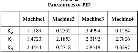
Self-tuning method is used to get parameters of the PID controller for each machine. The final results are shown in Table 2.
TABLE 2.
PARAMETERS OF PID
Machine1 Machine2 Machine3 Machine4
K
p 1.1189 0.2352 3.4994 0.1264K
i 1.4723 2.1853 2.3192 2.7806 [image:4.612.327.558.266.415.2] [image:4.612.49.285.327.440.2] [image:4.612.53.276.543.646.2] [image:4.612.326.561.604.694.2]International Journal of Emerging Technology and Advanced Engineering
Website: www.ijetae.com (ISSN 2250-2459,ISO 9001:2008 Certified Journal, Volume 4, Issue 8, August 2014)
416
V. RESULTS AND DISCUSSIONS
Three scenarios including i).multiband power system stabilizer (MB_PSS) with simplified setting (Std. 421.5)
includes conventional AVR (Ka = 200, τa = 0.001 sec.),
ii).MB_PSS with AVR using MPC controller, and iii).proposed system are tested under the condition of a three-phase fault at the middle of the two areas A1 and A2 (Bus no. 8) at t=1 sec. This fault represents a short-circuit between all three phases and the ground with transition times equal to [1 sec. 1+12/60 sec.] but this fault is cleared in 8 cycles by opening a circuit breaker (a three-phase breaker lies between the output of bus 7 and 110 km line connected to bus 8) and another breaker (three-phase breaker lies between the output of bus 9 and 110 km line connected to bus 8). Such a situation leads to change the operating conditions seriously.
Figure 5 shows the simulation results of the system with the three schemes in this case. The results from the top to the bottom are: the rotor mechanical angle of G1, G2, and G3 versus that of G4, machine speed, power acceleration (difference between the machine mechanical power and output electrical power in pu) and the terminal voltage (all for G1). The figure indicates that with the proposed scheme, the mechanical angles go to steady state with more damping and without any overshoot. The figures report also a good machine speed response in transient and steady state conditions. Similarly, both of the power acceleration and terminal voltage have a good damping characteristic with the proposed PID-MPC controller. In brief, it has been noticed that the system with the proposed controller has a good performance against the three-phase fault.
In order to validate the effectiveness of the proposed scheme, the results of the proposed controller are compared with a MB-PSS with conventional AVR and MB-PSS with AVR using MPC controller which was used in Ref. [1].
0 1 2 3 4 5 6 7 8 9 10
0 100 200 d -t h e ta v s G 4 (d e g re e )
0 1 2 3 4 5 6 7 8 9 10
1 1.01 s p e e d o f G 1 (p u )
0 1 2 3 4 5 6 7 8 9 10
-0.2 0 0.2 P a f o r G 1 (p u )
0 1 2 3 4 5 6 7 8 9 10
0.5 1 1.5 Time (s) V t fo r G 1 (p u ) MB-PSS+AVR MPC controller PID-MPC controller (b) (c) (d) (a) (b) (c) (d)
FIG.5.SYSTEM RESPONSE WITH MB-PSS+AVR,MPC CONTROLLER
AND PROPOSED PID-MPC CONTROLLER:
(A) THE ROTOR MECHANICAL ANGLE OF G1,G2, AND G3 VERSUS THAT
OF G4,(B) MACHINE SPEED,(C) POWER ACCELERATION AND (D) THE
TERMINAL VOLTAGE (ALL FOR G1).
0 1 2 3 4 5 6 7 8 9 10
0 100 200 d -t h e ta o f G 1 v s G 4 (d e g re e )
0 1 2 3 4 5 6 7 8 9 10
0.98 1 1.02 s p e e d o f G 1 (p u )
0 1 2 3 4 5 6 7 8 9 10
200 400 600 time (s) p o w e r tr a n s . fr o m A 1 t o A 2 ( M W ) MB-PSS+AVR MPC controller PID-MPC controller (c) (b) (a)
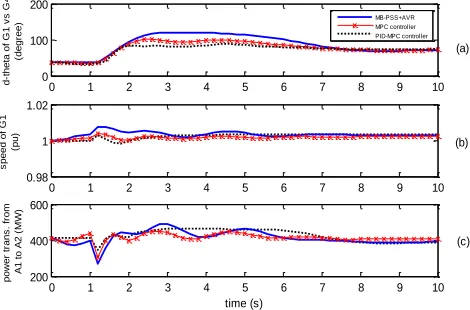
FIG.6.POWER SYSTEM RESPONSE WITH THE PROPOSED CONTROLLER
VERSUS OTHER THREE CONTROLLERS:
(A) THE ROTOR MECHANICAL ANGLE OF G1 VERSUS THAT OF G4,(B)
MACHINE SPEED OF G1, AND (C) THE POWER TRANSFER FROM A1 TO
[image:5.612.328.561.148.333.2] [image:5.612.331.566.412.567.2]International Journal of Emerging Technology and Advanced Engineering
Website: www.ijetae.com (ISSN 2250-2459,ISO 9001:2008 Certified Journal, Volume 4, Issue 8, August 2014)
417
Figure 6 shows the results using the three controllers. The results from the top to the bottom are: the rotor mechanical angle of G1 versus that of G4, machine speed of G1, and the power transfer from A1 to A2. From the figure, it is clear that for the rotor mechanical angle, a good transient response can be investigated using the proposed PID-MPC controller, as shown in Fig. 6-a. Also, the figure depicts that, In addition, the proposed controller with PID-MPC is very effective in damping the oscillation of the power transfer comparing to the other controllers as shown in Fig. 6-c. Fig. 6-b, indicates that the closed-loop oscillation frequency of the proposed controller with PID-MPC controller is superior to the other controllers in transient conditions. This refers to the ability of the proposed PID-MPC technique to recover the case of operating conditions changing efficiently.
VI. CONCLUSION
This paper presents a AVR system using proportional-integral-derivative control with model predictive control technique to improve the stability of a wide-area power system with multiple generators. Digital simulations have been carried out in order to validate the effectiveness of the proposed scheme. The proposed controller has been tested through a three-phase power fault at the middle of the studied two areas. Results showed that the dynamic response of the system is improved. A performance comparison between the proposed controller and some of other controllers (MB-PSS+AVR, MPC controller) has been carried out confirming the superiority of the proposed technique. In addition, a simple generator model is employed in the structure of the MPC controller. Therefore, beside the advantages of the PID controller, the proposed robust AVR with the proposed PID-MPC controller is simple and reliable.
REFERENCES
[1] T. H. Mohamed, A. Mohammed A.-R., A. Abd-Eltawwab H., Takashi Hiyama. 2011. Wide-area Power System Oscillation Damping using Model Predictive Control Technique, IEEJ Trans. on Power and Energy, Vol.131, No. 7, 536-541.
[2] K. Hirayama, Y.T., K. Takagi, H. Murakami, M. Shibata, H. Nagamura, Y. Takagi, , ―Digital AVR application to power plants‖. IEEE Transactions on Energy Conversion, 1993. 8(4): p. 602-609. [3] Bevrani H, Watanabe M, Mitani Y. 2014. Power system monitoring
and control, Wiley-IEEE Press, New York, USA
[4] IEEE Committee Reports: "Computer Representation of Excitation System", IEEE Trans. Power Apparatus Syst., Vol.PAS-87, No. 6 (1968-6)
[5] Morari M, Lee JH. 1999 .Model predictive control: past, present and future. Comp. Chem. Eng.; 23(4-5):667-82.
[6] Li Y., Ang. KH, Chong GCY. Mag 2006. PID control system analysis and design. IEEE Control Syst.; 26(1):32-41.
[7] J. Thomas, D. Dumur, J. Buisson and H. Gueguen. 2004. " Model Predictive Control for Hybrid Systems under a State Partition based MLD Approach (SPMLD)," International conference on informatics in control, automation and robotics ICINCO’04, Vol. 3, pp. 78-85, Setúbal.
[8] C.W. De Silva. 2008. Mechatronic systems: devices, design, control, operation and monitoring, CRC Press, Taylor & Francis Group . [9] E.F. Camacho and C.Bordons. 1999. Model Predictive Control.
Springer-Verlag, London .
[10] Finch JW, Zachariah KJ, Farsi M. 1999. Turbo generator self-tuning automatic voltage regulator. IEEE Trans Energy Conversion; 14(3):843–8.
[11] Brasca CL, Johnson MA. 1994. On automatic voltage regulator design for synchronous generators. In: Proceedings of the third IEEE conference on control applications, vol. 1; p. 199–205.
[12] Ula A, Hasan AR. 1992.Design and implementation of a personal computer based automatic voltage regulator for a synchronous generator. IEEE Trans Energy Conversion; 7(1):125–31.
[13] Kundur P. 1994. Power system stability and control. New York: McGraw-Hill.
[14] Yoshida H, Kawata K, Fukuyama Y, Takayama S, Nakanishi Y. 2000. A particle swarm optimization for reactive power and voltage control considering voltage security assessment. IEEE Trans Power Syst.; 15:1232–9.
[15] Gaing ZL. 2004. A particle swarm optimization approach for optimum design of PID controller in AVR system. IEEE Trans Energy Conversion; 19(2):384–91.