f-MAC: A Deterministic Media Access Control
Protocol Without Time Synchronization
Utz Roedig, Andre Barroso and Cormac J. Sreenan
Mobile and Internet Systems Laboratory (MISL),
Computer Science Department, University College Cork (UCC), Ireland {u.roedig,a.barroso,c.sreenan}@cs.ucc.ie
Abstract. Nodes in a wireless network transmit messages through a shared medium. Thus, a Media Access Control (MAC) protocol is neces-sary to regulate and coordinate medium access. For some application ar-eas it is necessary to have a deterministic MAC protocol which can give guarantees on message delay and channel throughput. Schedule based MAC protocols, based on time synchronization among nodes, are cur-rently used to implement deterministic MAC protocols. Time synchro-nization is difficult and costly, especially in energy constrained sensor networks. In this paper the f-MAC protocol is presented which can give guarantees regarding message delay and channel throughput without the requirement of time synchronization among nodes. The various trade-offs of f-MAC are analysed and discussed and application areas that would benefit from f-MAC are presented.
1
Introduction
Nodes in a wireless network transmit messages through a shared medium. Thus, some form of organization among the nodes is necessary to enable an effective usage of the shared resource. This organization is implemented by a Media Access Control (MAC) protocol that each node has to obey. Currently a number of varying MAC protocols with different properties and requirements exist. These properties might be high data throughput or transmission delay guarantees. Requirements might be time synchronization among all nodes or the capability of detecting a busy channel (carrier sense).
Most MAC protocols used in wireless networks today can be divided into two major classes: contention andschedule based MAC protocols. Both types differ in their properties and requirements.
A schedule based MAC protocol is more difficult to implement because accu-rate time synchronization among neighbouring nodes is required. Each node uses a dedicated time slot to transmit messages. As fixed time slots are used, guar-antees regarding bandwidth and message delay can be given. The main problem of such a MAC protocol is the complexity introduced by time synchronization. Especially in highly constrained sensor networks the synchronization overhead might not be acceptable.
This paper presents the f -MAC protocol which overcomes the aforemen-tioned restrictions. The protocol has, among other benefits shown in the paper, the following main features:
1. Bandwidth and delay guarantees are provided. 2. Time synchronization among nodes is not necessary.
The f-MAC protocol uses a framelet approach: fixed sized frames are retrans-mitted a fixed number of times with a specific frequency. Thus, the abbreviation f-MAC is used to refer to the presented protocol. As it will be shown in the paper, the capability of giving guarantees is traded for a lower bandwidth and higher transmission delay. However, for many application areas this is acceptable as hard guarantees are considered to be the most important design goal.
The remaining paper is organized as follows. In Section 2, the functionality and requirements of f-MAC are described. In Section 3 basic properties such as bandwidth and transmission delay are investigated analytically and by exper-iment. Section 4 compares the delivery probability of a simple random MAC with f-MAC. Section 5 describes cluster forming issues in larger f-MAC based networks. Section 6 shows application areas that benefit from the use of f-MAC. In Section 7 related work is discussed. Section 8 concludes the paper.
2
f-MAC Concept
In this section, the basic concept of f-MAC is presented. f-MAC uses a framelet approach as it is described in detail in [1].
2.1 The Framelet Approach
In the framelet approach, the same message is transmitted several times using small, fixed sized data packets. Each data packet of the transmission is called a framelet. A message transmission via the framelet approach is depicted in Fig. 1. The transmission duration of a framelet is denoted asd. Each transmission consists ofrframelets and the framelets are sent with a frequency off = 1/t.
A framelet approach is normally used to increase transmission reliability or to allow a power efficient operation of the transceivers (see [1,2], implementation of duty cycles). As the same information is transmitted several times, the available bandwidth is reduced. However, in many cases reliability and especially power efficiency is considered more important than a high throughput.
1 d
Framelet n1
second message first message
[image:3.595.287.472.200.274.2]t
Fig. 1.Framelet transmission.
T t’ t’
t’
3
2 1
n n
3 2 1
n
t t
t
3
Fig. 2.f-MAC operation.
2.2 Collision handling using Framelets
Instead of using the framelet approach to increase transmission reliability or to allow power efficient transceiver operation, it can be used to deal with the problem of collisions. If several nodes in the same radio range transmit data via a set of framelets, collisions can still occur. However, if each node uses a specific unique framelet transmission frequency fi, it is possible to ensure that
one framelet of a set is always received, even if collisions are not prevented. This is the basic idea behind the f-MAC protocol and is explained in detail in the next paragraph.
2.3 Framelet Media Access Control
In f-MAC, no collision detection or time synchronisation between the nodes is used. The number of framelets per message and the framelet frequencies are selected such that it is guaranteed that at least one framelet per message is de-livered without collision. f-MAC defines the following simple transmission policy:
Rule#1 Each node has to transmit messages as framelets. The framelet length
dis defined by the f-MAC base unitδas follows:
d=δ/2 (1)
Rule#2 The number of frameletsrper message is defined by the number of nodesN in transmission range.
[image:3.595.145.257.229.275.2]Rule#3 Each node ni has to use a specific framelet frequency fi = 1/ti =
1/(ki·δ). Theki∈N+ must satisfy the following equation:
ki·(r−1)< LCM(ki, kj) ∀ki< kj 1≤i, j≤N (3)
Rule#4 After the start of the transmission of the last framelet of a message, a node must wait at least the time t′ before a next message can be transmitted.t′ is computed as:
kmax= max
0≤i≤N{ki}
t′= (k
max·(r−1) + 1)·δ (4)
From the previous described rules it can be deduced that a nodeni needs in
the worst case the following timeTito transmit a message:
Ti= (r−1)·ti+t′ (5)
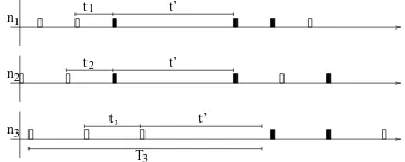
Example Fig. 2 shows an example with three nodes (N = 3). The number
of framelets is therefore r= 3. A possible1 set of k
i satisfying Equation (3) is k1= 4,k2= 5 andk3= 6. According to Equation (4), the nodes use t′= 13·δ. In the example it is assumed that n2 starts first at an arbitrary time with a message transmission. Shortly after,n3and thenn1start a transmission as well. In the example, framelet#3 ofn1 and n2 collide. However, all other remaining framelets of each node’s ongoing transmissions can be transmitted successfully. After the timet′of noden
1andn2expires, both nodes start immediately a new transmission. Here framelet#1 ofn1andn2 collide and are destroyed. However a framelet of each transmission can be subsequently submitted successfully.n3 sends a message some time after its waiting period t′ is over. Framelet#1 of this transmission collides with framelet#2 of the ongoing transmission of node
n1. Framelet#2 of the transmission of n3 collides with the framelet#3 of n2. However the last framelet ofn3’s transmission is successfully transmitted.
2.4 Validation
The previous stated example shows that the transmission scheme is feasible under certain conditions. However, it has to be shown that the transmission scheme is successful for all possible time shifts between the nodes.
Lemma 1. If node ni sends u (u∈N+) consecutive messages mi,u and node
nj sends v (v ∈N+) consecutive messagesmj,v, only framelets of exactly one
messagemi,u can collide with framelets of exactly one messagemj,v.
1 This set ofk
Proof. Assume for the sake of contradiction that framelets of message mi,u−1 andmi,uwithu6= 1 collide with messagemj,v. For this to happen, the following
equation must be fulfilled (see Equation 5):
t′ <(r−1)·tj+δ
The origin of this inequality can be described using the example shown in Fig. 2. The inequality describes the case where a message transmission ofn2does fit between two consecutive transmissions ofn1. This inequality can be simpified the following way:
(kmax·(r−1) + 1)·δ <(kj·(r−1) + 1)·δ⇒kmax< kj
According to f-MAC Rule#4 and Equation 4, this statement can not be fulfilled and thus contradicts the initial assumption.
Lemma 2. If node ni and node nj transmit a message, no more than one
framelet of these two message transmissions can collide.
Proof. Assume that more than one framelet of the transmission collide. There-fore, after one collision happened,ni and nj must send again a framelet at the
same time. This can only be achieved ifkiandkjhave a least common multiplier
within the periodki is sending its framelets. This can be expressed as follows:
LCM(ki, kj)< ki·(r−1) ∀ki< kj 1≤i, j≤N
This statement obviously contradicts Rule#3 and Equation 3 and thus con-tradicts the initial assumption.
Theorem 1. At least one framelet of any message transmission will be
trans-mitted collision-free (f-MAC theorem).
Proof. According to Lemma 1 and 2 only one framelet collision per message transmission between two nodes can occur. According to f-MAC Rule#2 and Equation 2 exactly r = N framelets are transmitted. Thus, even under worst case conditions, only N −1 framelets can be affected by a collision as a node cannot produce a collision with itself.
3
f-MAC Properties
Two important properties of a MAC protocol are the message delay and the available bandwidth. For most MAC protocols, the figures of these properties vary with the number of nodes that participate in a collision domain. This is observed as well within f-MAC and analyzed within this section.
Regarding bandwidth it has to be pointed out that f-MAC’s design goal is not an optimisation of the channel utilisation. In fact, the channel utilisation is reduced to enable strict guarantees for the message delay. Therefore, f-MAC has a naturally poor channel utilisation.
3.1 Worst Case Message Delay
The upper bound for the message delay between two nodes is given by the time
Tmax.Tmax is computed the following way using Equation 5:
Tmax= max
0≤i≤N{Ti} (6)
f-MAC ensures that after a delay of Tmax a message is delivered between
two arbitrary nodes. This is the worst-case delay bound for all nodes. If just one specific node is investigated, it might be possible to give a better upper bound of the message delay. This is possible as some nodes are able to transmit messages faster than others (They have aTi < Tmax). Thus, the worst case delay bound Tmin for the fastest node of the set is defined as:
Tmin= min
0≤i≤N{Ti} (7)
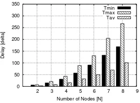
To analyse how the timesTminandTmaxincrease with the number of nodes,
a program was implemented to determine the combination of ki for a givenN
that leads to a minimalTmax. The result of this computation is shown in Table 1
andTmin andTmax are shown graphically in Fig. 3 (The valueTav is explained
[image:6.595.333.470.450.551.2]and obtained by simulation in Section 3.3).
Table 1. Sets satisfying the f-MAC condition.
N Setki TminTmax Tav
2 {2,3} 6δ 7δ 3δ
3 {2,3,5} 15δ 21δ 8δ
4 {3,4,5,7} 31δ 43δ 16δ
5 {3,5,7,8,11} 57δ 89δ 32δ
6 {5,7,8,9,11,13} 91δ 131δ 50δ
7 {5,7,8,9,11,13,17} 133δ 205δ 70δ
8 {5,9,11,13,14,16,17,19}169δ 267δ 101δ
0 50 100 150 200 250 300 350
2 3 4 5 6 7 8 9
Delay [delta]
[image:6.595.133.309.503.597.2]Number of Nodes [N] Tmin Tmax Tav
Fig. 3. Transmission delay Tmin and
TmaxandTav.
It also has to be noted that the gap betweenTmin andTmax increases with
the number of nodes. Some nodes are able to send messages faster than others. This feature might be useful in cases where specific nodes have to deal with a high traffic load.
Example If, for example, N = 5 nodes are selected and a Nordic nRF2401
transceiver [3] with a message size of b= 32 bytes and a transmission speed of 1M bit/sis assumed, the following value for the transfer delay bound is obtained:
δ= 2·0.25ms= 0.5 ms ⇒ Tmax= 89·0.5 ms= 44.5ms
3.2 Bandwidth
The available bandwidth Bi between two arbitrary nodes is given by the time Ti and the fixed framelet sizebin byte.
Bi= b Ti
(8)
The available maximum bandwidth Bmax (at the node using the smallest ki) and minimal available bandwidth Bmin can thus be calculated using Tmin
andTmax. The available bandwidth decreases exponentially as it depends on the
exponentially increasing message delay boundTi.
Example If, for example, N = 5 nodes are selected and a Nordic nRF2401
transceiver [3] with a message size of b= 32 bytes and a transmission speed of 1M bit/sis assumed, the following value is obtained:
Bmin=
32byte
44.5ms = 7.2 kbit
s
In this example, the maximum bandwidth is available for the node with
ki= 3. In this caseTmin is:
Tmin= (r−1)·ti+t′i= 4·03·δ+ 45·δ= 57·δ ⇒ Bmax= 11.23 kbit
s
This small example shows that some nodes have aTi < Tmax and therefore
have a higher bandwidth available.
3.3 Average Message Delay
As previously described, f-MAC guarantees that a message is delivered within the timeTmax between arbitrary nodes. However, as each message transmission
bound for the message transfer delay was calculated. In this section, the average message transfer delayTavbetween nodes is determined by simulation for specific
traffic patterns.
If a node wants to transmit a message using the f-MAC protocol, three factors contribute to the observed message delay. First, the nodenimight have to wait
for a portion oft′ before it is allowed to start the transmission of the framelets containing the message (see Section 2.3, f-MAC rules). Second, it depends which framelet of the framelet trail sent the receiver gets first. Third, the transfer delay depends on theki of the f-MAC set the node is using to transmit. A node with
a smallki repeats the framelets relatively fast and thus the receiver has a high
chance to catch an uncollided framelet early.
One can expect that the average message transfer delayTav is less than the
guaranteed message delivery timeTmax. Obviously, the resulting average message
transfer delay depends on the network configuration used and the particular traffic pattern.
Experiment The f-MAC protocol was implemented within a simulation
envi-ronment. Thens2 network simulator was used for the experimental evaluation. For the experiment,N nodes (2≤N ≤8) are setup to transmit to one base station (star topology). All N nodes are in the communication range of each other and the base-station.
For the experiment, a Nordic nRF2401 transceiver [3] with a message size of
b= 32 bytes and a transmission speed of 1M bit/sis assumed. Thusδ= 0.5msis used. Each of theNnodes creates new messages according to a Poisson distribu-tion. The arrival rateλis the same at each node. Throughout all experiments, an arrival rate of a quater of the maximum possible rate, determined by the minimum available bandwidthBminis used.
The experimentally obtained values ofTav are shown together with the
an-alytically obtained results of Tmin and Tmax (see Section 3.1) in Table 1 and
Fig. 3. As expected, the experiments show that the average message transfer de-lay is considerably better than the guaranteed maximum message transfer dede-lay. If the arrival rateλis increased, the transfer delay Tav increases as more single
framelet collisions occur. As expected,Tavis always - regardless of theλselected
- smaller than Tmax.
Furthermore, the experiments show that the communication among all nodes can take place without any collision. The experiments show as well that the f-MAC protocol implementation is relatively simple. To complete a full f-f-MAC implementation, only 100 lines of C++ code were necessary. This simplicity makes the MAC protocol useful for implementation in the very constrained sen-sor network environment.
3.4 Findings
1. The available bandwidth drops exponentially with the number of nodes. 2. The worst case delay increases exponentially with the number of nodes.
Therefore, it can be concluded that f-MAC is beneficial in sparsely populated networks where each node has only a few neighbours.
However, the experiments show that in realistic traffic scenarios, the worst case is not necessarily equal to the average operational case. Therefore the aver-age messaver-age delayTav is significantly smaller than the worst case message delay Tmax.
4
Delivery Probability Analysis
f-MAC provides 100% message delivery if it is assumed that messages are only lost due to collisions. In this section, the collision probability of a simple random transmission scheme is investigated. It is analysed how close such a simple MAC protocol will get to the design goal of 100% collision-free message delivery.
Under real world conditions, even a collision-free protocol can not guarantee 100% message delivery as the wireless channel is lossy2. Thus, one could argue that a MAC protocol does not need to be 100% collision-free; it would be enough if the probability of a message loss is not significantly increased by an additional collision probability. It is therefore of interest to know how a more primitive MAC protocol with properties similar to f-MAC performs regarding its collision probability. The comparison allows us to assess the operation conditions that justify the use of f-MAC instead of a more simple solution.
4.1 Random Transmission Scheme
The MAC protocol used for comparison with f-MAC is similar to the MAC protocol described and analysed in detail in [13].
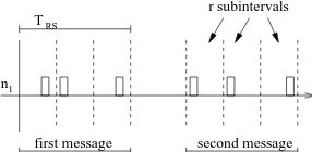
The protocol is selected because it uses a framelet approach comparable to f-MAC. Different to f-MAC, the transmitted r framelets are distributed in a random fashion within the time intervalTRS. The time intervalTRS is divided
in r subintervals. A framelet of the current message is submitted within each subinterval. The transmission time of the framelet in the subinterval is given by a uniformly distributed random variable on [0,(TRS/r)−δ/2] (Fig. 4).
The resulting MAC protocol is simpler than f-MAC as no coordination (care-ful determination of the ki) among neighbouring nodes is needed. Bandwidth
and delay bounds of the protocol are equal to f-MAC ifTRS=Tmaxis selected.
Basically, the collision-free behaviour of f-MAC is traded for simplicity of the described random MAC.
2 It has to be noted that TDMA based protocols also have to deal with lossy media
Table 2.Delivery probability P of the random transmission scheme.
N Tmax PST PBT
2 7δ 0.651428 0.640000
3 21δ 0.944530 0.858846
4 43δ 0.984797 0.944530 5 89δ 0.998696 0.989094 6 131δ 0.999716 0.995770 7 205δ 0.999975 0.999134 8 267δ 0.999995 0.999667
RS
first message n1
second message T
r subintervals
Fig. 4.Random transmission scheme.
4.2 Traffic Analysis
f-MAC attains a message delivery probability equal to 1 if it is assumed that only collisions will be responsible for packet losses. IfN nodes are contending for transmission, then f-MAC requires each node to transmit r=N framelets and every message will have been delivered afterTmax. With the random transmission
scheme, a message is transmitted within the timeTRS but the message could be
lost due to collisions. Thus, the probabilityP of a successful transmission is less than 1 (P <1).
Saturated Traffic In this comparison it is assumed thatN nodes contending
for the media are sending messages with the maximum available rate. If f-MAC is used in this traffic scenario, a message is sent every Ti seconds, depending
on the nodes specific ki. If the random scheme is used, every node is sending a
message everyTRS seconds. To enable a fair comparison - both schemes provide
the same bandwidth - the following value forTRS is selected:TRS =Tmax. In
this scenario, f-MAC attains a message delivery probability equal to 1. For the analytic analysis it is assumed that all nodes start the transmission of messages at the same point in time. In this case, the random transmission scheme attains a transmission probability that can be calculated the following way:
P(TRS) = 1−
1−
TRS
N −δ
TRS
N −
δ
2
!2N
N
(9)
The probability depends on the number of nodes that are in communication range of a potential message receiver. The delivery probabilityPST =P(TRS= Tmax) is shown in Table 2. For smallN, the delivery probability is significantly
lower than 100%. In this operation area, the usage of the more complicated f-MAC sceme instead of the imsple random scheme is justified.
Bursty Traffic In this traffic scenario, it is assumed that sporadically an event
[image:10.595.224.401.527.564.2]example described in Section 6). The time between events is assumed to be far larger than Tmax. Consequently, the channel will be temporarily saturated as
nodes contend for transmission. Such a channel usage is for example likely if the nodes are sensor nodes. The sensor nodes in one area of the field might be triggered by the same event that all nodes are set-up to monitor.
If f-MAC is used in this case, messages are guaranteed to be delivered after the time: (r−1)·ti+δ/2 (the waiting timet
′
must not be considered, as it is assumed that messages of previous events have been completely processed by the system). For comparison purposes, the same delivery time should be achieved by the random scheme. Thus,TRS = (r−1)·tmax+δ/2 is selected.
The delivery probabilityPBT can be calculated using Equation (9). PBT = P(TRS = (r−1)·tmax+δ/2) is shown in Table 2. Here again, the delivery
probability for small N is significantly lower than the 100% achieved by the f-MAC protocol.
4.3 Findings
In the real world, collision-free is not equal to 100% message delivery probability. Channel loss by interference will occur as well. However, in sparsely populated networks (small N), the probability of a message loss by collision can be con-siderable if a simple MAC protocol is used. f-MAC can reduce the number of message losses significantly as only message losses due to lossy links occur. Thus, f-MAC can be considered useful in sparsely populated networks with bursty traf-fic patterns if the link quality is not too bad.
5
f-MAC Clusters
The f-MAC scheme described previously allows only a collision-free delivery if all nodes participate in the scheme. Thus, if a large number of nodes have to communicate (e.g. many wireless sensors in a sensor field), the following problem arises. The number of framelets per transmission r is equal to the number of nodesN in the field. Additionally,kmaxmight be a high number so that Rule#3
can be satisfied. This will result in a largeTmaxwhich finally defines the upper
bound for transmission latency and the lower bound for bandwidth.
This problem can be attenuated by forming clusters. In most cases, not all nodes will be within the transmission range of all other nodes. Alternatively, the transmission power of the nodes can be dynamically adjusted such that only a few nodes are in transmission range of each other. Thus, the f-MAC scheme can be applied in localized areas that are formed by nodes that are within each others radio range.
5.1 Cluster Example
C1. Within the cluster, the different ki have to be selected according Rule#3.
For examplek1 = 3,k2 = 5 andk3 = 7 can be used. Within clusterC2, which comprises the next set of nodes that are in each others radio range, theki have
to be selected. As n2 is member of 2 different clusters, it will use the already selected k2 = 5. n5 and n6 can not select the same ki used by n1 and n3 due to the hidden terminal problem. If for example n5 would usek5 = 3, messages sent by n1 and n5 to n2 might collide at n2. Thus, cluster C1 and C2 must obey the f-MAC rule set together. After computing the equations in Rule#3, the following set of ki can be chosen for the clusters: k1 = 3, k2 = 5, k3 = 7,
k4= 8,k5= 11. Now, inC1andC2kmax= 11 is obtained and the upper bound
for the transmission delay isTmax= 89·δ. ClusterC3, containing another three nodes (n5, n6, n7) can now be added in a more simplistic way.k5 = 11 can be maintained, forn6 k6 = 3 can be selected asn1 is not in the collision domain ofC3. For the same reason,k7= 7 can be selected for n7. Now the clusters are setup and can be used with the f-MAC protocol.
n2 n5 n6 n1
n3 n4 n7
C2 C3 C1
R
Fig. 5.f-MAC cluster forming. Fig. 6.Noise-event detection.
5.2 Cluster Forming
Obviously, a method is necessary to form clusters and compute the ki after a
field is first set-up. This can be done statically after deployment, or a dynamic protocol for cluster forming has to be used. This paper focus on the investigation of the basic features of f-MAC and therefore cluster forming techniques are not discussed in this paper.
6
f-MAC Application Areas
The first application is the use of f-MAC to realise deterministic sensor net-works. As f-MAC provides hard guarantees on the information transfer delay, it can be used as one building block of a sensor network that can guarantee proper functioning in all possible operation cases. The second application is the use of f-MAC to realise a sensor network that is used for time critical event detection. For both described areas other solutions than f-MAC exist. However, for some characteristics of the described applications, f-MAC represents the better solution.
6.1 Worst Case Dimensioning
Application areas for wireless sensor networks may encompass production surveil-lance, road traffic management, medical care or military applications. In these areas it is crucial to ensure that the sensor network is functioning even under worst case circumstances.
Analytical tools such as network calculus can be used to determine the numer-ical range of network properties such as message transfer delay and node buffer requirements [7]. It is then possible to dimension the sensor nodes in a way such that all possible (even the worst cases) traffic scenarios can be supported by the network. Supported means here that the specifications regarding message transfer delay or node buffer requirements stay within the defined bounds at any time.
To implement a sensor network that complies with the analytically deter-mined specifications, deterministic network components are necessary. For ex-ample it is necessary to give a maximum upper bound for the message forward-ing delay. Hence it is necessary to have a deterministic MAC layer. Contention based MAC protocols do not provide these guarantees. Collisions may occur and a back-off time is necessary. It is not possible to give an upper bound for the amount of back-offs that are necessary to transmit a message successfully. Thus, scheduled based MAC protocols are used if deterministic behaviour of the MAC protocol is required. These protocols have the desired deterministic behaviour but need a complicated and energy expensive time synchronisation among the nodes.
f-MAC provides the necessary deterministic behaviour in the MAC layer without costly time synchronisation. Thus, f-MAC can be seen as a building block for wireless sensor networks with deterministic behaviour.
6.2 Time Critical Event Detection
of the event a message is generated and sent to the base station. If the base station knows now when each of the sensors detected the event, it can calculate the position of the noise source. This is possible because the sound wave needs different times to reach each of the sensors.
Each sensor node places a time-stamp in each message sent towards the base station. Either a time synchronisation among the nodes is used or the base station determines the time offset of each node after the measurement was reported [6]. However, time synchronisation among nodes might not be possible or is too costly and the determination of time offsets after event detection needs additional protocol steps.
To work around these problems, f-MAC can be used. Each node detecting an event can immediately send a message to the base-station. The base station can then, knowing which framelet of a transmission was received and which ki was
used, compute the time when the event was detected. This is possible as f-MAC provides a deterministic message delay. In this case no time synchronization among the nodes or additional protocol steps are necessary. Another advantage of using f-MAC for the described application is the fact that collisions can be handled. The detection of the acoustic event is very close together in time at each sensor. Therefore, if a contention based MAC protocol would be used, collisions would occur and the nodes would need to deal with this problem as well. This will increase the hardware complexity of the sensor node; an f-MAC sensor is simpler as it only has to send the framelets (no carrier sensing feature is necessary).
For the given application scenario, f-MAC provides a simpler alternative solution.
7
Related Work
MAC protocols for sensor networks can be coarsley classified in two groups: con-tention based and schedule based. Examples of concon-tention based protocols are S-MAC [8] and T-MAC [9]. Representatives of the schedule based approach are TRAMA [10] andµ-MAC [11]. The primary design goal of most MAC protocols for the area of wireless networks is energy efficiency and channel utilization. The primary design goal of the presented f-MAC protocol in contrast is a determin-istic, collision-free behavior without time synchronization.
F-MAC shares with the contention based approach the lack of coordination between contending nodes for shared medium access. However, f-MAC differs from the cited contention based approaches because it is able to prevent message losses due to collisions with 100% guarantee. Schedule based protocols are are able to ensure collision-free communication but they invariably require some form of coordination between nodes. Mainly, time synchronisation among nodes is used which is not required in in the presented f-MAC protocol.
bit-wise OR of the transmission. This feature can be used for specific applications in sensor networks. Additionally Bitmac has, similar to f-MAC, a deterministic be-haviour. In difference to f-MAC, Bitmac requires synchronisation (time-division multiplexing) among nodes.
8
Conclusion
The paper presented the f-MAC protocol that allows the implementation of a deterministic MAC layer without the need of time synchronization among the nodes. The protocol is collision-free and thus gives hard guarantees on message transfer delays and available bandwidth. The price for the deterministic behavior is a low channel utilization. However, some application scenarios might require a deterministic behavior and not necessarily a high throughput.
As shown, the message transfer delay increases exponentially with the num-ber of nodes present in the same collision domain. Similarly, bandwidth degrades exponentially with the number of nodes in the same collision domain. Therefore, in most cases, f-MAC is only useful in sparsely populated networks.
The protocol is relatively simple to implement and therefore useful in areas where nodes are resource constrained. A timer is necessary within each node to implement the protocol. This timer is needed to time the transmission of the framelets and to measure when a next message can be transmitted. This timer has to be accurate only during the relatively short transmission time of one mes-sage. Thus, relatively simple clocks can be used which helps an implementation of f-MAC in constrained environments.
As the delivery of at least one framelet of a message is guaranteed, a node does not have to perform a carrier sense. This is advantageous in a wireless environment as a reliable carrier sensing mechanism is difficult to implement. Additionally, the protocol deals with the hidden terminal problem. Two nodes which are not in radio range of each other can send simultaneously to a third node without additional protocol mechanisms (e.g. a CTS/RTS mechanism).
If power consumption has to be optimised within a network, f-MAC can be tuned in a way that duty cycles are implemented. In this case a message is repeated j times by a node (a message is sent j times using r framelets for each message transmission). The receiver can then alter between a short energy intensive listen period and a long energy saving sleep period (sleepingj−1 times, awake 1 time). In this case, the message delay is increased by the factorj.
Clustering is necessary if f-MAC is used in a larger network. The cluster con-figuration might be obtained by a clustering protocol or via static concon-figuration. Within a mobile environment, this might lead to an unacceptable communica-tion overhead to maintain a cluster structure. Therefore, f-MAC might be only suitable for a non mobile network environment.
Consolidated, f-MAC is useful in constrained, static and sparsely populated networks where guarantees on the message transport delay are required.
the sensor network environment. Currently we are incorporating the protocol in our sensor platform to evaluate the protocol in a real environment.
Acknowledgments
The support of the Informatics Research Initiative of Enterprise Ireland is grate-fully acknowledged.
References
1. B. O’Flynn, A. Barroso, S. Bellis, J. Benson, U. Roedig, K. Delaney, J. Barton, C. Sreenan, and C. O’Mathuna. The Development of a Novel Miniaturized Mod-ular Platform for Wireless Sensor Networks. In Proceedings of the IPSN Track on Sensor Platform, Tools and Design Methods for Networked Embedded Systems (IPSN2005/SPOTS2005), Los Angeles, USA, April 2005.
2. S. Mahlknecht and M. Boeck. CSMA-MPS: A Minimum Preamble Sampling MAC Protocol for Low Power Wireless Sensor Networks. In Proceedings of the 5th IEEE International Workshop on Factory Communication Systems (WFCS2004), Vi-enna, Austria, September 2004.
3. Nordic Inc. nRF2401 Single Chip 2.4GHz Radio Transceiver Data Sheet, 2002. 4. NannoNET. nanoNET TRX Transceiver Data Sheet, http://www.nanotron.com. 5. Chipcon. CC2420 Transceiver Data Sheet, http://www.chipcon.com, 2004. 6. G. Simon, M. Maroti, A. Ledeczi, G. Balogh, B. Kusy, A. Nadas, G. Pap, J. Sallai,
K. Frampton: Sensor Network-Based Countersniper System, SenSys 04, Baltimore, USA, November 2004
7. J. Schmitt and U. Roedig. Sensor Network Calculus - A Framework for Worst Case Analysis. In Proceedings of the International Conference on Distributed Computing in Sensor Systems (DCOSS05), Marina del Rey, USA, June 2005.
8. W. Ye, J. Heidemann, and D. Estrin. An energy-efficient MAC protocol for wireless sensor networks. In Proceedings of the IEEE Infocom 2002 (INFOCOM2002), New York, USA, June 2002.
9. T. van Dam and K. Langendoen. An adaptive energy-efficient mac protocol for wireless sensor networks. In Proceedings of the First ACM Conference on Em-bedded Networked Sensor Systems (SenSys 2003), Los Angeles, USA, November 2003.
10. V. Rajendran, K. Obraczka, and J. Garcia-Luna-Aceves. Energy-efficient, collision-free medium access control for wireless sensor networks. In Proceedings of the First ACM Conference on Embedded Networked Sensor Systems (SenSys 2003), Los Angeles, USA, November 2003.
11. A. Barroso, U. Roedig, and C. J. Sreenan. u-MAC: An Energy-Efficient Medium Access Control for Wireless Sensor Networks. In Proceedings of the 2nd IEEE European Workshop on Wireless Sensor Networks (EWSN2005), Istanbul, Turkey, January 2005.
12. M. Ringwald and K. Roemer. BitMAC: A Deterministic, Collision-Free, and Ro-bust MAC Protocol for Sensor Networks. Proceedings of 2nd European Workshop on Wireless Sensor Networks (EWSN 2005), Istanbul, Turkey, January 2005. 13. B. Davidson and C. Bostian. A One-Way Packet Communication Channel with