http://dx.doi.org/10.4236/cs.2016.76074
How to cite this paper: Anand, S. and Gloria, J.J.P. (2016) RF MEMS Based Reconfigurable Rectangular Slotted Self Similar Antenna. Circuits and Systems, 7, 859-876. http://dx.doi.org/10.4236/cs.2016.76074
RF MEMS Based Reconfigurable Rectangular
Slotted Self Similar Antenna
S. Anand, J. Josephine Pon Gloria*
Department of Electronics and Communication Engineering, Mepco Schlenk Engineering College, Sivakasi, India
Received 18 March 2016; accepted 14 May 2016; published 17 May 2016
Copyright © 2016 by authors and Scientific Research Publishing Inc.
This work is licensed under the Creative Commons Attribution International License (CC BY).
http://creativecommons.org/licenses/by/4.0/
Abstract
Wireless communication systems which require flexibility and reconfigurability in antenna sys-tems faces main problems like antenna performance, size, weight and cost. A wide band Frequency Reconfigurable Rectangular Slotted Self Similar Antenna has been proposed in this paper. The rectangular slotted patch is repeated for two iterations at different scales and is separated by means of Radio Frequency Micro Electro Mechanical Systems (RF MEMS) switches in order to pro-vide reconfigurability. The antenna can operate in three frequency bands i.e. K-band, Ku-band and Ka-band by altering the states of RF MEMS switches. To avoid fringing effects and to improve an-tenna performance, quarter wavelength (λ/4) spacing is required between the antenna and the ground plane. However, a Reconfigurable Antenna requires different λ/4 spacing which is difficult to achieve using a common ground plane. So the Frequency Reconfigurable antenna is integrated with high impedance surface (HIS) like Electronic Band Gap (EBG) structures to suppress standing waves and surface waves with a unified profile thickness of 1.75 mm. The overall dimension of the proposed antenna along with RF MEMS Switch, feed element and HIS is about 8 mm × 8 mm × 1.75 mm. The simulated results of the proposed antenna reveal enhancement in antennas performance like Voltage Standing Wave Ratio (VSWR), Front to Back Ratio (FBR) and bandwidth when it is placed over HIS EBG. Also the radiation patterns of the proposed antenna when placed over EBG shows the suppression of side lobe and backward radiation.
Keywords
Frequency Reconfigurable Antenna, Radio Frequency Micro Electro Mechanical Systems, High Impedance Structure, Self Similar Structures
1. Introduction
received a considerable attention due to its effective usage of the spectrum. The upcoming wireless communica-tion systems like Radars and satellite communicacommunica-tion requires frequency reconfigurability along with better fre-quency selectivity and reliable system performances. The other requirements like good Front to Back Ratio (FBR), suppression of the standing and surface waves, bandwidth enhancement, compact size and stable radia-tion patterns must also be satisfied.
Self Similar antennas are beneficial in reconfiguration because of their self similarity, recursive definition, compact size and multiband or wideband behavior. Its intricate shape leads to many electric current modes and thus gives rise to multiple resonances. These multiple resonances in turn are brought together and is made to overlap in order to achieve multiband or wideband [1]-[8].
Reconfigurable Antennas efficiently utilize the frequency spectrum by modifying its frequency and radiation characteristics in a controlled mode [9]-[12]. Frequency Reconfigurable Antennas are generally recognized by the usage of PIN diodes, Varactor diodes or Micro Electro Mechanical Systems (MEMS). PIN diodes are commonly used in frequency reconfigurable antennas because they are inexpensive and are abundantly avail-able on the market. However the high power loss and deprived quality factor restrict its applications [13]-[16]. The application of varactor diodes in antennas has continuous frequency tuning ability and simplified circuit complexity. But it has the disadvantages like low dynamic range, high power loss and nonlinearity [17]-[20]. MEMS switches have some benefits over PIN diodes and varactor diodes such as lower insertion and power losses, higher linearity and higher quality factor. Though the disadvantages of MEMS switches like longer switching time and higher control voltage can be overcome using structural alteration of MEMS switches. So for better switching characteristics MEMS switches are preferable for Frequency Reconfigurable Antennas [21]-[24].
In order to reduce standing waves and to achieve good FBR the antennas are modeled over a metal sheet which acts as a reflector or ground plane. The ground plane redirects half of the radiation in the opposite direc-tion. When the antenna element is too close to the ground plane image currents cancel each other and lead to poor radiation efficiency. Also, practically the edge of the finite ground plane gives rise to multipath lobes and more power is wasted in the backward direction. So always a quarter wavelength spacing is required between the antenna element and the ground plane. In Frequency Reconfigurable Antennas the configuration requires different quarter wavelength spacing to achieve different operating frequency bands which are difficult to be achieved using a single ground plane reflector. To overcome this problem the High Impedance Surface (HIS) like Electronic Band Gap (EBG) can be used which has unique characteristics like surface and standing wave suppression and in-phase reflection phase characteristics. EBG can be placed only at several tenths of wave-length between the antenna element and the ground plane for all operating frequency bands [25]-[28].
In this paper, the proposed Reconfigurable Rectangular Slotted Self Similar Antenna can operate in three fre-quency bands, i.e. K-band, Ku-band, and Ka-band, by changing the states of RF MEMS switches. The proposed antenna provides reconfiguration along with size compatibility. In order to achieve a good return loss, FBR and VSWR at resonant frequencies, a triple-band EBG is presented as a reflector, which has in-phase reflection bands and out of phase reflection bands for all the above mentioned three bands. So the antenna configuration has a unified profile thickness of 1.75 mm for different frequency reconfigurable bands. The simulated results reveal that when the ground plane is replaced by EBG structure, there is tremendous improvement in antenna performance like bandwidth, VSWR, FBR and return loss along with size compaction.
2. Proposed Method
The High-Impedance Surface (HIS) are usually recognized by periodic metallic patches, dielectric structures or metallic-dielectric structures. They have two exceptional characteristics: the surface wave reduction feature and the in-phase reflection phase property. Due to their exclusive characteristics, HIS-EBG structures have oc-cupied a good deal of attention. In this paper the proposed antenna can provide Ultra Wide Band (UWB) range of frequencies in K-band, Ku-band, and Ka-band, by changing the states of RF MEMS switches. In order to achieve a modest design and good return loss in resonant frequency range, a triple-band HIS is presented as a reflector. The proposed antenna is placed over a ground plane with a finite distance of 0.5 mm between antenna and ground plane, over a ground plane with λ/4 spacing of 2 mm between the antenna and ground plane and over HIS-EBG structure. The results reveal enhancement in antennas performance like VSWR, FBR and bandwidth when it is placed over HIS comparatively with the antenna element placed over the ground plane with finite dis-tance and λ/4 spacing.
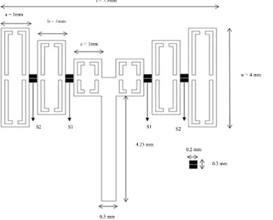
[image:3.595.124.520.382.702.2]2.1. Design of Proposed Rectangular Slotted Self Similar Antenna
Figure 1shows the geometry of the proposed frequency reconfigurable self similar antenna. The two arms of
the Rectangular Slotted Self Similar Antenna are printed on opposite sides of the dielectric substrate in the form of a bow tie structure and is fed by using a micro strip line. As illustrated in Figure 1, l is the total length of an-tenna arm, w is the width of antenna arm, a, b and c refer to rectangular slotted patch width at different scales. In order to satisfy the requirement of reconfigurable frequency bands, the scale factor is a:b:c = 1:1:1. The para-meter values of proposed antenna are as follows l = 7.5 mm, w = 4 mm, a = 1 mm, b = 1 mm, c = 1 mm.
The RF MEMS switches are of dimension 0.3 mm × 0.2 mm. It can be seen that only two switches in one arm are needed to control three states, and the corresponding switches in two arms are controlled by DC biasing vol-tage simultaneously. When both S1 and S2 switches are ON, the antenna works in Ku-band. When S1 is ON and S2 is OFF, the antenna operates in K-band. When both S1 and S2 are OFF, the antenna will operate in Ka-band.
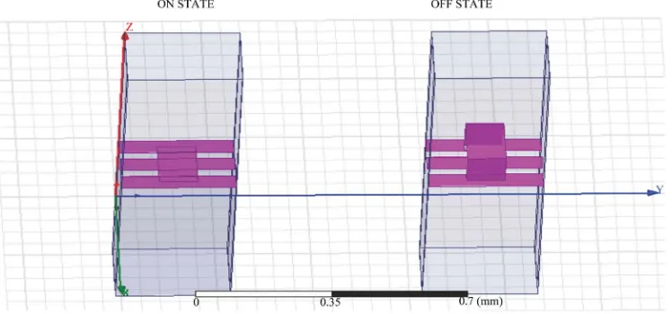
2.2. Design of RF MEMS Switch
A RF switch is a two port network that is used for making or breaking a RF circuit. The traditional RF switches based solid state devices like diodes and transistors are limited in performance because of low power handling ability, high resistive losses,etc. MEMS switches are more popular because of higher better isolation, low losses and ability to operate at very high frequencies but with limited power handling capability and reducible DC vol-tage. A shunt capacitive MEMS switch consists of a thin metallic membrane bridge suspended over the center conductor of a micro strip line. RF MEMS switch uses the same substrate of the antenna with a substrate of thickness (td) and dielectric constant (εr). The physical parameters like length (l) and width (w) are assumed
ac-cording to the antenna design with characteristic impedance z0 = 50. The above mentioned parameter values are
taken as td = 0.254 mm; εr = 2.94; l = 0.3 mm; w = 0.2 mm for the design of both upstate and down state as
shown inFigure 2.
The up state capacitance comprises of fringing capacitance and parallel plate capacitance and is given in Equ-ation (1) as
0 0 u d r A C t g ε ε = + (1)
The down state capacitance is obtained using Equation (2)
0 r d d A C t ε ε
= (2)
where A—area of the overlaying bridge, td—thickness of the substrate, g0 is the initial gap between the CPW
center conductor and the MEMS membrane.
The shunt switch is placed in shunt between the transmission line and the ground. Depending on the applied bias voltage, it either leaves the transmission line undisturbed or connects it to the ground. Therefore the ideal shunt switch, which results in zero insertion loss when no bias is applied (Up state position) and infinite isola-tion when bias, is applied (Down state posiisola-tion).
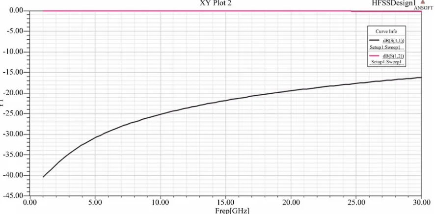
The switching action in upstate is the reverse action in down state. FromFigure 3 andFigure 4 it is clear that in on and off states it produces a negligible insertion loss and high isolation for very high frequencies i.e.) even up to 30 GHz. The insertion loss so produced is less than −0.03 dB.
2.3. Design of High Impedance Structure
[image:4.595.128.502.524.699.2]High Impedance Surface EBG (HIS EBG) structure, provides high surface impedances for both Transverse Electric (TE) and Transverse Magnetic (TM) waves and can suppress surface wave propagation at certain fre-
Figure 3. Down (on) state performance of RF MEMS switch that shows insertion and isolation loss.
Figure 4. Up (off) state performance of RF MEMS switch that shows insertion and isolation loss.
quency band gap. The proposed HIS is shown inFigure 5, which consists of an array of square metal patches on the top surface that are overwhelmed in order to produce in-phase reflection in the desired bands and a metal sheet on the bottom surface of a substrate. They are arranged in a two-dimensional lattice, without metal plated vias. As shown inFigure 5, w is the width of the square patch, s is the width of the square slot, n is the width of the inner patch, g is the gap width, t is the substrate thickness, and εris the permittivity of the dielectric substrate.
The initial HIS parameter values are given as follows: w = 3.5 mm, s = 0.25 mm, n = 2.5mm, g = 1 mm, h = 1.5 mm, εr = 3.
Wavelength is given in Equation (3) as
0
C f
λ= (3)
[image:5.595.97.540.327.545.2]Figure 5. High impedance structure.
Inductance is given in Equation (4) as
0 r
L=µ µh (4)
Capacitance is given in Equation (5) as
(
)
10 1 cosh
π
r
w g
w
g C
ε ε −
+ +
=
(5)
Resonant frequency is given in Equation (6) as
1 2π
r
f
LC
= (6)
where w is the width of the patch, s is the width of the square slot, g is the gap width, h is the substrate thickness, εr is the permittivity of the dielectric substrate. Length of the patch must be quarter the wavelength and is
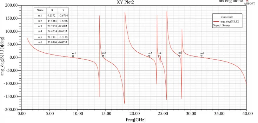
FromFigure 6 it is clear that the reflection phase characteristics varies from ±180 degree and also at 0 degree in K-band, Ku-band and Ka-band and hence it acts as both Perfect Electric Conductor (PEC) and Artificial Magnetic Conductor(AMC) and thereby reduces or suppresses the standing waves. The in-phase reflection bands may be obtained from ±90 degree and are obtained at 14.5465 GHz, 22.7838 GHz, 24.4234 GHz, 28.1321 GHz and 32.0360 GHz, respectively. The square slots impressed in the square patches play an important role to produce in-phase reflection bands.
3. Performance Analysis of Rectangular Slotted Self Similar Antenna
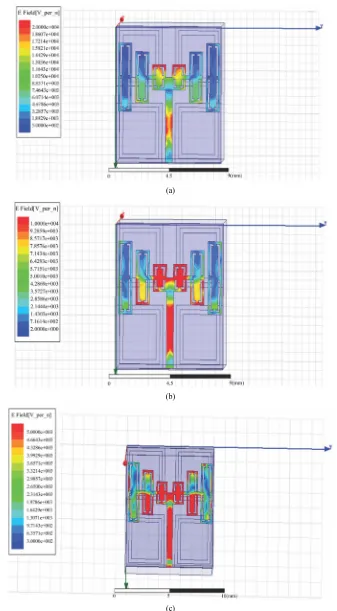
Current Distribution pattern shows how the current has been distributed in the antenna patch through the feed element. Figure 7 shows the current distribution of the proposed Rectangular Slotted Self Similar Antenna in Ka-band i.e. both switches in OFF state, K-band i.e. S1 in ON state and S2 in OFF state and Ku-band i.e. both switches in ON state.
Due to the presence of switches S1 and S2 the current propagation is blocked in corresponding antenna patch area when they are in off state. When S1 and S2 are in on state the current propagates freely throughout the en-tire antenna patch area.
3.1. Antenna Placed over PEC with Minimum Substrate Thickness (0.5 mm)
The proposed antenna is placed over PEC with reduced substrate thickness of 0.5 mm. When both S1 and S2 are OFF, the antenna operates in Ka-band. When S1 is ON and S2 is OFF, the antenna operates in K-band. When both S1 and S2 are ON, the antenna operates in Ku-band.
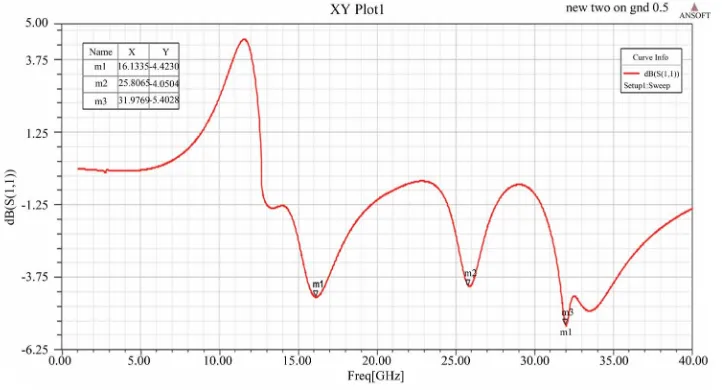
[image:7.595.91.542.484.700.2]While placing the antenna over PEC with minimum substrate thickness of 0.5 mm there occurs poor antenna performance due to fringing effects and image current cancellation by the ground plane as shown in Figures 8-10. So quarter wavelength spacing is required between the antenna element and ground plane. When S1 and S2 are OFF, the Frequency Reconfigurable Antenna works in Ka-band alone. The operating frequency so ob-tained in the Ka-band is at 31.61 GHz. When S1 is ON and S2 is OFF, the Frequency Reconfigurable Antenna works in K-band and Ka-band. The operating frequencies so obtained in the K-band and Ka-band are at 23.77 GHz and 33.17 GHz. When S1 and S2 are ON, the Frequency Reconfigurable Antenna works in all the three bands. The operating frequencies so obtained in the three bands are at 16.133 GHz, 25.8065 GHz and 31.9769 GHz. But while placing the antenna over PEC with minimum substrate thickness of 0.5 mm, standing and sur- face waves occurs due to which the VSWR of the antenna exceeds 2. Also the FBR is not upto the expected lev-el.
(a)
(b)
[image:8.595.142.479.79.690.2](c)
Figure 8. Return Loss performance of proposed rectangular slotted self similar antenna placed over PEC with minimum substrate thickness of 0.5 mm when S1 and S2 are in OFF state (Ka band).
Figure 9. Return Loss performance of proposed rectangular slotted self similar antenna placed over PEC with minimum substrate thickness of 0.5 mm when S1-ON and S2-OFF state (K band).
[image:9.595.136.497.496.691.2]3.2. Antenna Placed over PEC with Quarter Wavelength Substrate Thickness (2 mm)
In order to avoid the fringing effects and to suppress surface and standing waves quarter wavelength spacing is required between the ground plane and the antenna element. Infinite ground planes provide no radiation in backward direction. But practically ground plane with finite distance from the antenna element are preferred. Due to this the edges of the ground plane contributes multipath lobes and nulls at various angles. So, more pow-er is wasted in the backward direction.
[image:10.595.111.517.186.413.2]Figures 11-13shows the return loss performance of the antenna in Ka-band, K-band and Ku-band respec-
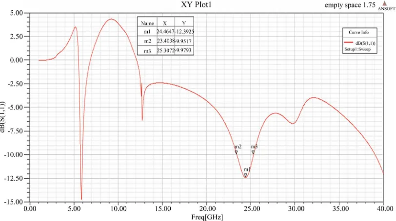
Figure 11. Return Loss performance of proposed rectangular slotted self similar antenna when S1 and S2 are in OFF state with λ/4 spacing (Ka band).
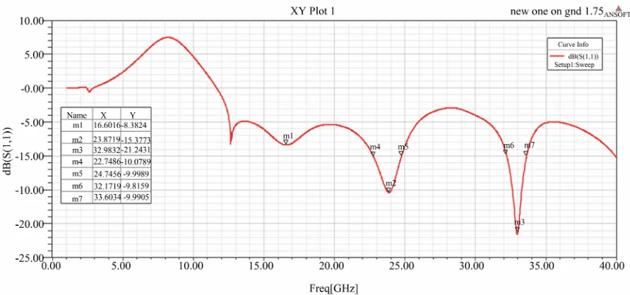
[image:10.595.102.525.450.694.2]Figure 13. Return Loss performance of proposed rectangular slotted self similar antenna when S1 and S2 are in ON state with λ/4 spacing (Ku band).
tively. Figures 14(a)-(c)shows the radiation pattern of the antenna in Ka-band, K-band and Ku-band respec-tively. It is clearly shown that the performance has been improved only for Ka-band and not for the other bands. Because in the proposed method the quarter wavelength spacing is given according to the maximum frequency band. However for a Reconfigurable Antenna the antenna structure requires different quarter wavelength spac-ing accordspac-ing to the different operational frequency bands. For e.g. Ka band requires a quarter wavelength spacing of 2 mm, K band requires a quarter wavelength spacing of 3.5 mm and Ku band requires a quarter wa-velength spacing of 5 mm. This is difficult to be adjusted by using a common ground plane.
When S1 and S2 are OFF, the Frequency Reconfigurable Antenna works in Ka-band alone. The operating frequency so obtained in the Ka-band is at 24.467 GHz. When S1 is ON and S2 is OFF, the Frequency Recon-figurable Antenna works in K-band and Ka-band. The operating frequencies so obtained in the K-band and Ka-band are at 21.65 GHz and 32.2031 GHz. When S1 and S2 are ON, the Frequency Reconfigurable Antenna works in all the three band. The operating frequencies so obtained in the three bands are at 16.6016 GHz, 23.8719 GHz and 32.9832 GHz. The normalized radiation patterns of the proposed Rectangular Slotted Self Similar Antenna shows the presence of side lobes and backward radiation. In order to suppress backward radia-tion HIS EBG structures may be used.
3.3. Antenna Placed over HIS EBG with Unified Substrate Thickness
In order to avoid the fringing effects by the ground plane and to overcome the quarter wavelength spacing from the ground plane, HIS EBG structures can be used with a substrate thickness of 1.5 mm. Thus the total profile thickness of the proposed antenna with HIS is 1.75 mm. HIS EBG structure, provides high surface impedances for both Transverse Electric (TE) and Transverse Magnetic (TM) waves and can suppress surface wave propa-gation at certain frequency band gap.
Figures 15-17 shows the return loss performance of the antenna when placed over HIS EBG in Ka-band,
K-band and Ku-band respectively. Figures 18(a)-(c) shows the radiation pattern of the antenna in Ka-band, K-band and Ku-band respectively. It is clearly shown that the performance has been improved for all the three bands.
(a)
(c)
Figure 14. Radiation pattern of proposed rectangular slotted self similar antenna over PEC with λ/4 spacing (a) Ka band (b) K band and (c) Ku band.
Figure 15. Return Loss performance of proposed rectangular slotted self similar antenna placed over HIS EBG when S1 and S2 are in OFF state (Ka band).
Slotted Self Similar Antenna when placed over HIS EBG shows the suppression of side lobes and backward radiation.
[image:13.595.90.538.424.621.2]Figure 16. Return Loss performance of proposed rectangular slotted self similar antenna placed over HIS EBG when S1-ON and S2-OFF state (K band).
Figure 17. Return Loss performance of proposed rectangular slotted self similar antenna placed over HIS EBG when S1 and S2 are in ON state (Ku band).
Table 1. Comparative analysis of the proposed rectangular slotted self similar antenna.
Parameters
S1 and S2-OFF S1-ON and S2-OFF S1 and S2-ON
PEC (0.5 mm)
PEC
(2 mm) EBG
PEC (0.5 mm)
PEC
(2 mm) EBG
PEC (0.5 mm)
PEC
(2 mm) EBG
Frequency (GHz) 31.6103 24.467 28.19 23.7783
33.1353 21.656 32.203 20.53 27.52 16.1335 25.8065 31.9769 16.601 23.872 32.983 16.35 22.09 27.71
Return Loss (dB) −6.0817 −12.392 −31.4 −3.3849 −5.2469 −13.303 −21.561 −24.6 −26.6
−4.423 −4.0504 −5.4028 −8.3809 −15.371 −21.238 −21.7 −20.6 −25.8
VSWR 2.9721 1.632 1.055 5.1969
3.4109 1.5516 1.18 1.124 1.098 4.012 4.366 3.31 2.23115 1.4107 1.1898 1.178 1.204 1.108
FBR (dB) 10.019 34.38 14.538 16.19 9.1986 19.06
Bandwidth (GHz) 1.9034 11.19 2.3753 12.54 1.997 19.78
Bandwidth
[image:14.595.88.539.534.718.2](a)
(c)
Figure 18. Radiation pattern of proposed rectangular slotted self similar antenna over HIS EBG (a) Ka band (b) K band and (c) Ku band.
4. Conclusion
The proposed frequency reconfigurable Rectangular Slotted Self Similar Antenna is integrated with High Im-pedance Surface for better performance and low profile design. Less number of RF MEMS switches is used to perform the frequency reconfiguration in three bands namely Ku-band, K-band and Ka-band. RF MEMS switches offer low loss and high isolation. The use of self similar structures in antennas offers broadband and multiband frequency response, compact size and robustness. The proposed reconfigurable antenna is first placed over PEC with minimum substrate thickness of 0.5 mm and at quarter wavelength spacing. The simulated results reveal that there occurs some problem due to fringing effects and requirement of unified quarter wavelength spacing during reconfiguration. In order to overcome such problems it is then placed over HIS EBG structure. The results reveal enhancement in antennas performance like VSWR, FBR and bandwidth when it is placed over HIS EBG, also an unified profile thickness of 1.75 mm is used to achieve frequency reconfiguration in all the three bands.
References
[1] Li, L. and Wu, Z. (2014) Frequency-Reconfigurable Quasi-Sierpinski Antenna Integrating with Dual-Band High-Im- pedance Surface. IEEE Transactions on Antennas and Propagation, 62.
[2] Li, D.-T. and Mao, J.-F. (2012) A Koch-Like Sided Fractal Bow-Tie Dipole Antenna. IEEE Transactions on Antennas and Propagation, 60, 2242-2251. http://dx.doi.org/10.1109/TAP.2012.2189719
[3] Lizzi, L. and Massa, A. (2011) Dual-Band Printed Fractal Monopole Antenna for LTE Applications. IEEE Antennas and Wireless Propagation Letters, 10, 760-763. http://dx.doi.org/10.1109/LAWP.2011.2163051
[4] Werner, D. and Ganguly, S. (2003) An Overview of Fractal Antenna Engineering Research. IEEE Antennas and Propagation Magazine, 45, 38-57.
http://dx.doi.org/10.1109/TSP.2003.815428
[6] Baliarda, C.P., Borau, C.B., Rodero, M.N. and Robert, J.R. (2000) An Iterative Model for Fractal Antennas: Applica-tion to the Sierpinski Gasket Antenna. IEEE Transactions on Antennas and Propagation, 48, 713-719.
http://dx.doi.org/10.1109/8.855489
[7] Kingsley, N., Anagnostou, D.E., Tentzeris, M. and Papapolymerou, J. (2007) RF MEMS Sequentially Reconfigurable Sierpinski Antenna on a Flexible Organic Substrate with Novel DC-Biasing Technique. Journal of Microelectrome-chanical Systems, 16, 1185-1192. http://dx.doi.org/10.1109/JMEMS.2007.902462
[8] Anagnostou, D.E., et al. (2006) Design, Fabrication, and Measurements of an RF-MEMS-Based Self-Similar Recon Figurable Antenna. IEEE Transactions on Antennas and Propagation, 54, 422-432.
[9] Raman, S., Mohanan, P., Timmons, N. and Morrison, J. (2013) Microstrip-Fed Pattern- and Polarization Reconfigura-ble Compact Truncated Monopole Antenna. IEEE Antennas and Wireless Propagation Letters, 12, 710-713.
http://dx.doi.org/10.1109/LAWP.2013.2263983
[10] Cetiner, B.A., Crusats, G.R., Jofre, L. and Biyikli, N. (2010) RF MEMS Integrated Frequency Reconfigurable Annular Slot Antenna. IEEE Transactions on Antennas and Propagation, 58, 626-632.
http://dx.doi.org/10.1109/TAP.2009.2039300
[11] Kulkarni, A.N. and Sharma, S.K. (2013) Frequency Reconfigurable Microstrip Loop Antenna Covering LTE Bands with MIMO Implementation and Wideband Microstrip Slot Antenna All for Portable Wireless DTV Media Player.
IEEE Transactions on Antennas and Propagation, 61, 964-968. http://dx.doi.org/10.1109/TAP.2012.2223433
[12] Cai, Y., Guo, Y.J. and Bird, T.S. (2012) A Frequency Reconfigurable Printed Yagi-Uda Dipole Antenna for Cognitive Radio Applications. IEEE Transactions on Antennas and Propagation, 60, 2905-2912.
http://dx.doi.org/10.1109/TAP.2012.2194654
[13] Majid, H.A., Rahim, M.K.A., Hamid, M.R., Murad, N.A. and Ismail, M.F. (2013) Frequency-Reconfigurable Micro-strip Patch-Slot Antenna. IEEE Antennas and Wireless Propagation Letters, 12, 218-220.
http://dx.doi.org/10.1109/LAWP.2013.2245293
[14] Pazin, L. and Leviatan, Y. Reconfigurable Slot Antenna for Switchable Multiband Operation in a Wide Frequency Range. IEEE Antennas and Wireless Propagation Letters, 12, 329-332.
http://dx.doi.org/10.1109/LAWP.2013.2246855
[15] Ge, L. and Luk, K.M. (2014) A Band-Reconfigurable Antenna Based on Directed Dipole. IEEE Transactions on An-tennas and Propagation, 62, 64-71. http://dx.doi.org/10.1109/TAP.2013.2287520
[16] Gonalves, R., Pinho, P. and Carvalho, N.B. (2012) Compact, Frequency Reconfigurable, Printed Monopole Antenna.
International Journal of Antennas and Propagation, 2012, Article ID: 602780.
[17] Hum, S.V. and Xiong, H.Y. (2010) Analysis and Design of a Differentially-Fed Frequency Agile Microstrip Patch An-tenna. IEEE Transactions on Antennas and Propagation, 58, 3122-3130. http://dx.doi.org/10.1109/TAP.2010.2055805
[18] White, C.R. and Rebeiz, G.M. (2009) Single- and Dual-Polarized Tunable Slot-Ring Antennas. IEEE Transactions on Antennas and Propagation, 57, 19-26.
[19] Tariq, A. and Ghafouri-Shiraz, H. (2012) Frequency-Reconfigurable Monopole Antennas. IEEE Transactions on An-tennas and Propagation, 60, 44-50. http://dx.doi.org/10.1109/TAP.2011.2167929
[20] Erfani, E., Nourinia, J., Ghobadi, C., Niroo-Jazi, M. and Denidni, T.A. (2012) Design and Implementation of an Inte-grated UWB/Reconfigurable-Slot Antenna for Cognitive Radio Application. IEEE Antennas and Wireless Propagation Letters, 11, 77-80. http://dx.doi.org/10.1109/LAWP.2011.2182631
[21] Boyle, K.R. and Steeneken, P.G. (2007) A Five-Band Reconfigurable PIFA for Mobile Phones. IEEE Transactions on Antennas and Propagation, 55, 3300-3309. http://dx.doi.org/10.1109/TAP.2007.908822
[22] Chiu, C.Y., Li, J., Song, S. and Murch, R.D. (2012) Frequency-Reconfigurable Pixel Slot Antenna. IEEE Transactions on Antennas and Propagation, 60, 4921-4924. http://dx.doi.org/10.1109/TAP.2012.2207334
[23] Grau, A., Romeu, J., Lee, M.J., Blanch, S., Jofre, L. and De Flaviis, F. (2010) A Dual-Linearly-Polarized MEMS-Reconfigurable Antenna for Narrowband MIMO Communication Systems. IEEE Transactions on Antennas and Propagation, 58, 4-17. http://dx.doi.org/10.1109/TAP.2009.2036197
[24] Yamagajo, T. and Koga, Y. (2011) Frequency Reconfigurable Antenna with MEMS Switches for Mobile Terminals. 2011 IEEE-APS Topical Conference on Antennas and Propagation in Wireless Communications (APWC), Torino, 12-16 September 2011, 1213-1216. http://dx.doi.org/10.1109/apwc.2011.6046834
[25] Chen, X., Li, L., Liang, C.-H. and Su, Z.-J. (2010) Locally Resonant Cavity Cell Model for Meandering Slotted Elec-tromagnetic Band Gap Structure. IEEE Antennas and Wireless Propagation Letters, 9, 3-7.
http://dx.doi.org/10.1109/TAP.2012.2207030
[27] Zhu, S.Z. and Langley, R. (2009) Dual-Band Wearable Textile Antenna on an EBG Substrate. IEEE Transactions on Antennas and Propagation, 57, 926-935. http://dx.doi.org/10.1109/TAP.2009.2014527