http://dx.doi.org/10.4236/epe.2015.711051
Simulink Based Analysis and
Realization of Solar PV System
S. Badie Asghar, R. K. Singh
1Department of Electrical and Electronics Engineering, MACET, Bihar, India 2Department of Electrical Engineering, MIT, Bihar, India
Email: [email protected],[email protected]
Received 28 June 2015; accepted 27 October 2015; published 30 October 2015
Copyright © 2015 by authors and Scientific Research Publishing Inc.
This work is licensed under the Creative Commons Attribution International License (CC BY). http://creativecommons.org/licenses/by/4.0/
Abstract
Non-conventional energy resources are increasingly used to fulfill load demands. Before using such energy sources, the very important thing is analysis at the basic level. This paper presents analysis and realization of solar PV system. The current-voltage and power-voltage characteristics of solar PV array changes as parameters like solar insolation, and temperature changes. These characteristics are found and realized by using MATLAB software.
Keywords
Effect of Ambient Conditions, Modeling of PV Cell, Series Parallel Connection of PV Cells, Solar PV System
1. Introduction
One of the major concerns in the power sector is the day-to-day increasing power demand but the unavailability of enough resources to meet the power demand using the conventional energy sources. Demand has increased for renewable sources of energy to be utilized along with conventional systems to meet the energy demand. Re-newable sources like wind energy and solar energy are the major energy sources which are being utilized in this regard. The continuous use of fossil fuels has caused the fossil fuel deposit to be reduced and has affected the environment emptying the biosphere and gradually adding to global warming.
2. Solar PV System
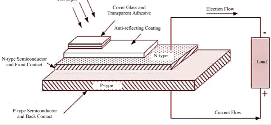
Photovoltaic cells convert radiant energy from the sun directly into electricity. Photovoltaic cell provides a clean, reliable energy without consuming fossil, and is free from hazardous product. Sun is the mother of all energies (except nuclear and geothermal) that provides almost all the energy needed to support life, and can be used in variety of applications. On average, the earth receives about 1.2 × 10¹⁷ W of solar power. The challenge for a sustainable future is to tap a tiny fraction of this energy to supply the relatively modest demands of human activ-ities. The increasing use of these solar cells is linked to economic, efficiency and reliability factors and recent advances in solid state technologies has given a boost to the attractiveness of solar cells with high efficiency so-lar cells now available. A Schematic block diagram of a PV cell is shown in Figure 1.
1) I-V Characteristics of solar cell
Solar cell generator is neither a constant voltage nor a constant current source. The current is proportional to solar insolation and voltage is a function of the current required by the load [1].
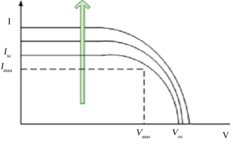
[image:2.595.121.541.284.703.2]A typical I-Vcharacteristic of the solar cell for a certain ambient irradiation S and a certain fixed cell temper-ature T is shown in Figure 2. For a resistive load, the load characteristic is a straight line with slope I/V = 1/R. It should be pointed out that the power delivered to the load depends on the value of the resistance only.
Figure 1. Schematic diagram of PV cell.
[image:2.595.98.535.291.493.2]2) Effect of Ambient Conditions on I-V Characteristics of PV Cell
The I-Vcharacteristics of a PV cell is weather dependent, the effect of change in ambient temperature and solar insolation on the I-Vcharacteristics is shown in Figure 3 and Figure 4 that the open circuit voltage de-creases linearly with the increase in the cell temperature and open circuit voltage inde-creases logarithmically with the ambient irradiation, while the short circuit current is a linear function of the ambient irradiation.
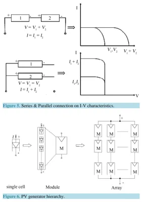
3) Effect of Series and Parallel Connection on I-V Characteristics of PV Cell 4) PV Generator Hierarchy
3. Modeling of Photovoltaic Cell
Photovoltaic (PV) system directly converts sunlight into electricity. The basic device of a PV system is the PV cell. Cells may be grouped to form panels or arrays. The voltage ¤t available at the terminals of a PV de-vice may directly feed small loads such as lighting systems and DC motors. More sophisticated applications re-quire electronic converters to process the electricity from the PV device .These converters may be used to regu-late the voltage and current at the load, to control the power flow in grid-connected systems, and mainly to track the maximum power point (MPP) of the device [2].
A PV device may be any element that converts sunlight into electricity. The elementary PV device is the PV cell. A set of connected cells form a panel. Panels are generally composed of series cells in order to obtain large output voltages. Panels with large output currents are achieved by increasing the surface area of the cells or by connecting cells in parallel. A PV array may be either a panel or a set of panels connected in series or parallel to form large PV systems. This paper focuses on PV arrays and shows how to obtain the parameters of the I-V eq-uation from practical data obtained in datasheets [3]. Series & parallel connection & PV hierarchy is shown in Figure 5 & Figure 6 respectively.
[image:3.595.196.434.371.520.2]Figure 3. Effect of temperature on I-V characteristics.
[image:3.595.193.435.549.709.2]Figure 5. Series & Parallel connection on I-V characteristics.
Figure 6. PV generator hierarchy.
3.1. Simplest Model (Ideal Case)
The simplest model of a PV cell and its equivalent circuit is presented in Figure that consists of an ideal current source in parallel with an ideal diode with zero series resistance, infinite shunt resistance and unity ideality fac-tor for junction.
The output current (IC) from the PV cell is found by applying the Kirchoff’s current law on the equivalent circuit in Figure 7.
C SC d
I =I −I (1)
where Isc is a short circuit current. The diode current Id is given by Shockley diode equation.
0 e
d
c
qV kT d
I I
=
(2)
Vd is the voltage across the diode (D). For the ideal case, this voltage is equal to the cell voltage, Vc;
k is Boltzmann constant (1.38 × 10⁻²³ J/K);
q is electron charge (1.602 × 10⁻¹⁹ C);
I0 is reverse saturation current of diode (0.000025 A);
Tc is reference cell operating temperature (25˚C).
Figure 7. Equivalent Circuit of PV cell (Ideal case). 0 1 e c c qV k c T Ph
I I I
− = − (3) 0 0 ln
c Ph c
c
kT I I I
V
q I
+ −
=
(4) The reverse saturation current of diode (I0) is constant under the constant temperature and found by setting the open-circuit condition, the open circuit voltage is obtained as:
0
0
ln
c Ph oc
kT I I
q I
V +
= (5)
As Iph I0 above equation can be written as:
0 ln oc c Ph kT I V q I
= (6)
To a very good approximation, the photon generated current, which is equal to Isc, is directly proportional to the irradiance, the intensity of illumination, to PV cell. Thus, if the value, Isc, is known from the datasheet, under the standard test condition, Sc = 1000 W/m
2
at the air mass (AM) = 1.5, then the photon generated current at any other irradiance, Sx in (W/m
2
), is given by:
-
-x sc sx s sc
c c
S S
I I
= (7)
3.2. More Accurate Model (Non-Ideal Case)
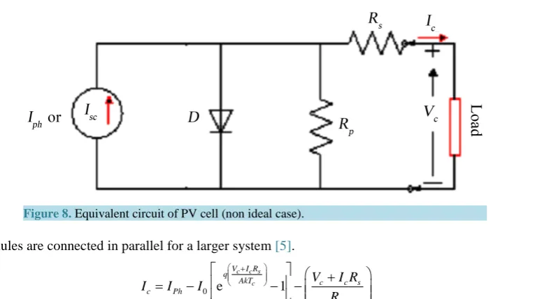
Some researchers on photovoltaic models use constant parameters (i.e. ideality factor A, series resistance Rs, and shunt resistance Rp,), which result in modeling inaccuracy. In reality, these parameters vary with the temperature change. For better results consideration of these effects is necessary. Figure 8 shows a more accurate equivalent circuit of a PV cell [4].
3.2.1. Series Resistance
In a practical PV cell, there is a series of resistance in a current path through the semiconductor material, the metal grid, contacts, and current collecting bus. These resistive losses are lumped together as a series resister (Rs). Its effect becomes very conspicuous in a PV module that consists of many series-connected cells, and the value of resistance is multiplied by the number of cells.
3.2.2. Parallel Resistance
Figure 8. Equivalent circuit of PV cell (non ideal case).
of PV modules are connected in parallel for a larger system [5].
0 e 1
c c s
c
V I R q AkT c P c s p h c
I I I V I R
R + = − − − + (8)
where A is known as the “ideality factor of junction” (“A” is sometimes denoted as “n”). After rearranging the above equation we can write I-Vequation as shown below:
0
0 0
ln
c Ph c c c s
c c s
P
AkT I I I V I R
V I R
q I I R
+ − +
= − −
(9)
4. Modeling of Solar PV System Using Matlab Simulink
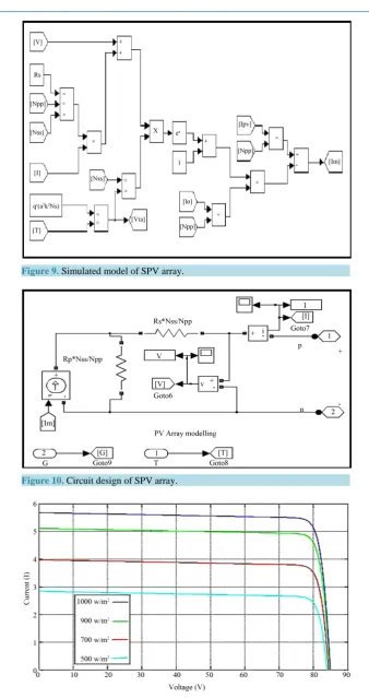
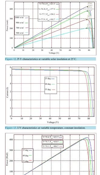
The MATLAB/SIMULINK software has been used for the modeling and simulation purposes [3] [6]. Model and circuit design for PV array are shown in Figure 9 and Figure 10 respectively.
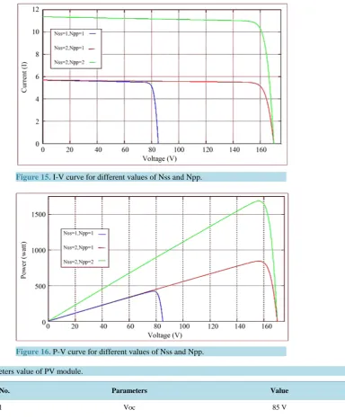
C. Parameters used in PV module for the different characteristics; A. I-V characteristics of solar array at variable solar insolation, 25˚C; B. P-V characteristics at variable solar insolation, 25˚C;
C. I-V characteristics at variable temperature, 1000 W/m2; D. P-V characteristics at variable temperature, 1000 W/m2;
E. I-V curve for different values of Nss and Npp at standard conditions; F. P-V curve for different values of Nss and Npp at standard conditions.
5. Conclusions
In order to answer the present energy crisis, one has to develop an efficient manner in which power has to be ex-tracted from the incoming solar radiation. The power conversion mechanisms have been greatly reduced in size in the past few years. The development in power electronics and material science has helped engineers to come up very small but powerful systems to withstand the high power demand. But the disadvantage of these systems is the increased power density.
The constant increase in the development of the solar cells manufacturing technology will definitely make the use of these technologies possible on a wider basis. The use of the newest power control mechanisms called the Maximum Power Point Tracking (MPPT) algorithms has led to the increase in the efficiency of operation of the solar modules and thus is effective in the field of utilization of renewable sources of energy [7].
Figure 9. Simulated model of SPV array.
Figure 10. Circuit design of SPV array.
Figure 12. P-V characteristics at variable solar insolation at 25˚C.
[image:8.595.160.468.509.710.2]Figure 13. I-V characteristics at variable temperature, constant insolation.
Figure 15. I-V curve for different values of Nss and Npp.
[image:9.595.88.535.503.698.2]Figure 16. P-V curve for different values of Nss and Npp.
Table 1. Parameters value of PV module.
S. No. Parameters Value
1 Voc 85 V
2 Isc 5.68 A
3 Ki 0.0032 A/K
4 Kv −0.1230 V/K
5 Ns 54
6 Nss 1
7 Npp 1
8 Imp 5.4 A
9 Vmp 78.4 V
10 Rs 0.221 ohm
References
[1] Ramos Hernanz, J.A., Campayo Martin, J.J. and Zamora Belver, I. (2010) Modelling of Photovoltaic Module. Interna-tional Conference on Renewable Energies & Power Quality. Granada, 23-25 March 2010.
[2] Villalva, M.G., Gazoli, J.R. and Filho, E.R. (2009) Comprehensive Approach to Modelling & Simulation of PV Arrays. IEEE Transactions on Power Electronics, 25, 1198-1208.
[3] Salmi, T., Bouzguenda, M., Gastli, A. and Masmoudi, A. (2012) Matlab/Simulink Based Modelling of Solar Photovol-taic Cell. International Journal of Renewable Energy Research, 2.
[4] Ghosh, S.K. (2013) Modelling of PV Arrays & Analysis of Different Parameters. International Journal of Advance-ments in Research & Technology, 2, 358-3623.
[5] Pongratananukul, N. Analysis & Simulation Tools for SPV Power Systems. PhD Dissertation, University of Central Florida, Orlando.
[6] Pandiarajan, N. and Muthu, R. (2011) Mathematical Modelling of Photovoltaic Module with Simulink. International Conference on Electrical Energy Systems (ICEES 2011), Newport Beach, 3-5 January 2011, 258-263.
http://dx.doi.org/10.1109/ICEES.2011.5725339