14
Abstract—Drying of biomass is crucial prior
utilizing its high intrinsic and readily available
energy. The reduction of moisture content is
mandatory to increase overall energy efficiency
and reduce emission in systems operating with
biomass, especially during combustion or
gasification. One of the established methods of
drying biomass is through fluidized bed drying.
As such, the current work addresses the
development of a biomass drying apparatus,
designated as the swirling fluidized bed dryer
(SFBD). The SFBD features an annular bed with
inclined injection of gas through an array of
blades which acts as the hot air distributor, which
then imparts the swirling motion to the bed. This
secondary motion inside the bed promotes the
highly desired mixing and solid-fluid contact. The
performance of SFBD was studied in terms of its
hydrodynamic characteristic using PVC beads
before tested with actual biomass from palm
frond. The results show that SFBD exhibits
excellent hydrodynamic characteristic with
distributor to bed pressure drop ratio less then
10%. It is also found that bed pressure drop is
proportional with superficial velocity of hot air,
but still reasonably low for bed weight up to 2 kg.
The findings lead to a conclusion that the SFBD is
capable of achieving good fluidization quality for
low bed heights and suitable for biomass drying,
especially that operates with batch processing.
Keywords: swirling fluidized bed, hydrodynamic, drying
This work was supported in part by Ministry of Science Technolgy & Innovation (MOSTI) and Universiti tu Huessein Onn Malaysia (UTHM).
Mohd Faizal is with the Faculty of Mechanical Engineering & Manufacturing, UTHM, 86400 Parit Raja, Batu Pahat, Johor, Malaysia (phone: +6074537787; fax: +6074536080; e-mail: [email protected]) Hamidon Salleh is also with the Faculty of Mechanical Engineering & Manufacturing, UTHM, 86400 Parit Raja, Batu Pahat, Johor, Malaysia (e-mail: [email protected]).
V.R. Raghavan is a Professor in the Faculty of Mechanical Engineering, Universiti Teknologi Petronas, 31750 Bandar Seri Iskandar, Tronoh, Perak (e-mail: [email protected]).
I. INTRODUCTION
he term biomass can be applied to any fuel type derived from recently living tissue. Biomass is a renewable, low carbon fuel that is widely and economically available throughout Malaysia. Its production and use also brings additional environmental and social benefits. Correctly managed, biomass is a sustainable fuel that can deliver a significant reduction in net carbon emissions when compared with fossil fuels. Biomass is also considered as the renewable energy source with highest potential to contribute to the energy needs of modern society for both the developed and developing economies world-wide [1,2]. However, biomass has to be dried first before the processes of deriving its energy begin, to ensure the desired thermal efficiency and acceptable emission obtained during the process. For example, in biomass combustion systems, any water content in the fuel must be driven off before the first stage of combustion can occur. This is mandatory because the moisture itself will consume energy, and thus reducing overall system efficiency and potentially reducing combustion temperature.
Reduction of combustion temperature below the optimum may result in incomplete combustion of the fuel and giving rise to the emission of tars and creosote which may condense in the flue, especially if it is long or includes changes of direction, and particulates. The water may also recondense in the flue, and all these may lead to corrosion of the flue and the gradual accretion of material leading to the potential for eventual blockages or fire. Similarly, in the process of gasification, many biomass gasifiers today are designed to operate on very low moisture content feedstock, perhaps 10-20%. Other technologies, such as anaerobic digestion, fermentation, hydrothermal upgrading and supercritical gasification all make use of feedstock in an aqueous medium, and are particularly suitable for very high moisture content biomass, and for which drying is unnecessary.
Fluidized bed drying had become common in drying of wet particulates and granular materials that can be fluidized. Fluidized bed dryers are commonly used in drying a variety of products such as chemicals, foodstuff, polymers, waste and also biomass [3]. In fluidized bed dryers, the particles are suspended in a stream of process gas (or air) whereby solids and the gas become into contacts, resulting good mixing and high heat and mass transfer rates, and eventually enhance drying.
Studies on Biomass Drying Apparatus Using Swirling Fluidization Technique
Mohd Faizal Mohideen Batcha, Hamidon Salleh and Vijay R. Raghavan
T
Malaysian Technical Universities Conference on Engineering and Technology June 20-22, 2009, MS Garden,Kuantan, Pahang, Malaysia
15 II. FLUIDIZED BED APPLICATION IN BIOMASS PROCESSING
Fluidized beds serve in numerous applications involving biomass processing such as combustion, gasification and drying. Some related studies are as follows:
A. Biomass Combustion
Combustion of biomass and related materials is widely practiced commercially to provide heat and power. The technology is commercially available and presents minimum risk to investors. The product is heat, which must be used immediately for heat and/or power generation as storage is not a viable option. Overall efficiencies to power tend to be rather low at typically 15% for small plants up to 30% for larger and newer plants. The presence of fluidized beds technology gave a boost to biomass combustion process. Overall thermal efficiency obtained apart from reduced emission. The technology is, however, widely available commercially and there are many successful working examples throughout North America and Europe, frequently utilizing forestry, agricultural and industrial wastes [7].
B. Biomass Gasification
Gasification is a process that converts carbonaceous materials, such as coal, petroleum, biofuel, or biomass, into carbon monoxide and hydrogen by reacting the raw material at high temperatures with a controlled amount of oxygen and/or steam. The resulting gas mixture is called synthesis gas or syngas and is itself a fuel. It can also be seen as a method for extracting energy from many different types of organic materials such as biomass. Fluidized bed technology provides good gas and solid mixing, uniform temperatures and high reaction rates; in comparison with fixed bed gasification, and it results greater tolerance to particle size range and safer operation due to good temperature control; in addition, tar cracking and reforming catalysts can be added to the bed inventory [8].
C. Biomass Drying
Commonly recognized advantages of fluidized beds in drying processes are high rate of moisture removal, high thermal efficiency, easy material transport inside dryer, ease of control and low maintenance cost [3]. Though some drawbacks such as poor fluidization and non-uniform quality, it remains as one of the best methods of drying. A variety of fluidized bed designed for drying, namely the conventional fluidized bed dryer, modified fluidized bed dryers, spouted bed dryers, circulating fluidized bed dryers and many more.
One of the recent developments in providing a variant in fluidized bed operation is the swirling fluidized bed (SFB). In contrast with conventional fluidization, a swirling fluidized bed imparts swirling motion to the bed particles. This paper describes the design of SFB and the early findings from experimental works, in terms of hydrodynamic characteristics and capability to be used as a fluidized bed dryer.
III. SWIRLING FLUIDIZED BED (SFB)
A . SFB Design
The bed is an annular type with a centre body while the distributor at the bottom of the bed is made by an array of
blades inclined at certain an angle to the horizontal plane. These blades form an annular ring with trapezoidal openings, thus designated as the annular distributor [4]. Fluidizing or process gas is now injected to the bed for fluidization, as shown in fig. 1.
The principle of operation is based on the simple fact that a horizontal component of gas velocity in the bed creates horizontal motion of bed particles. A jet of gas enters the bed at an angle θb to the horizontal. Due to angular injection,
the gas velocity has two components. The vertical component Uv = U sin θb, causes lifting of particles. It is this
lifting force that is responsible for fluidization. The horizontal component Uh = U cos θb, creates a swirling
motion of the particles [5]. The bed particles are also likely to undergo a secondary motion in a toroid-like path and be well mixed in the radial plane. The bed particles are also likely to undergo a secondary motion in a toroid-like path and be well mixed in the radial plane.
This variant of fluidized bed provides an efficient mean of contacting between gas and particles, providing extraordinary mass and heat transfer efficiency [6]. Apart from that, elutriation of particles which has always limited the operation of a conventional fluidized bed is reduced significantly, since the vertical component of velocity is now small fraction of the net gas velocity. The cyclone-like features resulting from the swirling motion of bed particles may also contribute to this low elutriation. Hence it is possible to fluidize fine particles and a wide variety of shapes of particles in this kind of fluidized bed.
B . Distributor Design
The choice and good design of gas distributors are essential for the satisfactory performance of fluidized beds and for successful industrial applications that use fluidization techniques. A good distributor design should meet many requirements that include uniform distribution of gas into the fluidized bed, operation at as low a pressure drop a possible to minimize power consumption, sufficient strength to withstand both thermal and mechanical stresses, prevention of particle fall back, reduction in particle attrition and prevention of plate erosion. Some of these requirements are contradictory and their relative importance may change with the process requirements [9].
As shown in fig. 1, the SFB uses the annular distributor.
process gas annular distributor
blades
Fig.1 Configuration of a swirling fluidized bed biomass
particles
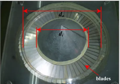
16 The distributor was made by a number of over-lapping blades shaped as sectors of a circle with gap between the blades as shown in fig. 2 and fig. 3. It can be seen that the distributor resembles truncated sectors which form an annular region of airflow between the outer and inner diameters of the distributor to reduce the variations in centrifugal forces acting radially outwards on the bed material. Centrifugal force imparted by the tangential component of air velocity due to the blade inclination results in the swirling motion of bed material in a circular path.
The gap between two consecutive blades is uniform and varies in proportion to the radius. This gap was largest at the bed wall and decreased towards the inner diameter of the distributor to form a trapezoidal cross section for the air flow path. The blades are made from stainless steel sheets of 1 mm thickness. The over-lapping length between two successive blades helps to direct the air at the designed angle.
C. Experimental Set-up
The schematic diagram of the test rig is given in Fig.4 while Fig. 5 shows the actual set-up. The unit consists of an acrylic column enclosing the bed that forms the bed wall. This column and the bed are mounted on top of the distributor. Pressure tappings are placed at the top part of the plenum chamber just before the air enters the bed and just after the distributor. Both pressure tappings are connected to a digital manometer to determine distributor pressure drop. Another pressure tapping was made above the bed to measure the bed pressure drop with different bed
configurations. The flow rate of air is measured using a venturi flowmeter.
Air enters the plenum chamber via tangential entry and expands before entering the annular distributor. The distributor assembly consists of lower and upper plates together with inner plates respectively, holding the blades firmly to form the annular distributor. Two types of centre bodies were used in the current work to observe the difference in distributor pressure drop, which is a cone and a cylinder. These centre bodies are important in a SFB design as it eliminates the possible creation of a ‘dead zone’ at the centre of the bed during operation with bed materials as reported by [5].
C. ExperimentalProcedure
The experiments were designed to bring out the effect of distributor and bed pressure drops and drying characteristics based on the following parameters:
- Number of blades : 30 & 60 - Superficial air velocity : up to 3.2 m/s - Centre-body : cone
IV. RESULTS & DISCUSSION
From the experiments, the pressure drop values of the distributor, ∆pd, the bed pressure drop, ∆pb, and drying
d
od
i [image:3.595.306.525.105.276.2]blades
Fig. 2 Top view of the SFB
[image:3.595.54.254.183.323.2]Xi Xo
Fig. 3 Blade arrangement and trapezoidal opening in the SFB distributor
1. BED WALL
2. CONE
3. DISTRIBUTOR
4. WIND BOX
5. AIR INLET
[image:3.595.326.533.323.481.2]Fig. 4 Schematic diagram of the experimental set-up
[image:3.595.53.252.359.517.2]17 characteristics are investigated. Data from experimental works are presented in the form of graphs in this section.
A. Distributor Pressure Drop vs Superficial Air Velocity The results of the distributor pressure drop, ∆pd, are as in
Fig. 6. Here the effect of using different number blades and different over-lapping length (O/L) are also studied.
Using different number of blades affect the distributor pressure drop significantly with the increase of superficial air velocity because the number of blades governs the fraction of open area, (FOA) for airflow inside the bed. By using smaller number of blades, which is 30 blades in our case, the distributor has larger FOA compared to that of 60 blades, imposing less resistance to airflow, yielding smaller
∆pd. However, aiming for smaller ∆pd should be avoided as
smaller ∆pd are likely to subject maldistribution of gas
inside the bed, which is undesirable in fluidization, as reported by [9] and [10]. Therefore, with respect to the type of process and biomass particles used in the bed, careful selection of number of blades should be made when operating with SFBs.
B. Bed Pressure Drop vs Superficial Air Velocity
Bed pressure drop values simply give an idea on how much energy is required to fluidize a bed of particles. By knowing so, one can design and select equipments such as blower and heater accordingly. In the current work, a bed of particles made from PVC having diameters of 5.9mm are used to characterize the SFB’s hydrodynamic characteristics. Only low bed weights (also low bed height), about 0.5 and 1 kg were used in the experiments since the SFB is most useful in its swirling condition where the energy transfer is at optimum. Higher bed height will eventually result in a 2-layer fluidization as reported by [5] and [9]. Fig. 7 represents the behaviour of bed pressure against the increase in superficial velocities.
Unlike in the conventional gas-solid fluidized beds, the pressure drop values continue to increase beyond the minimum fluidization velocity. This is due to the increase of friction in the peripheral direction (direction of rotation) as a result of higher centrifugal forces at higher superficial velocities. The particles in this state being pushed to the bed wall more intensely and thus explain the pressure drop increase. It is also found that with larger fraction of open area, FOA, due to the less number of blades, bed pressure drop values are much lower. However, it should be noted here that less pressure drops may also affect the quality of fluidization.
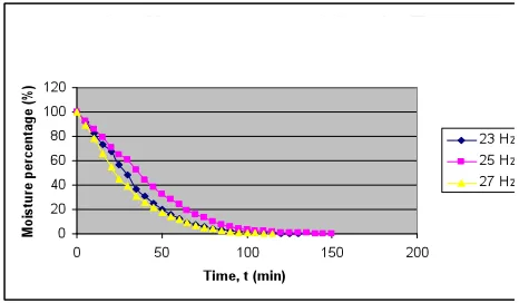
C. Drying Characteristics
Preliminary drying characteristics of hygroscopic material were also investigated in the current work. Cubic shaped chopped potatoes, having dimension approximately 10mm x 10 mm x 10mm are dried in the bed. The temperature of fluidizing air inside the bed is about 35ºC. Fig. 8 shows the moisture content inside potatoes being continuously reduced with respect to time. It can also be seen here that higher superficial velocity of air results in quicker drying. The findings agree very well with other researchers such as [11].
[image:4.595.311.546.61.221.2]Fig. 9 shows drying curve for the different bed weight of chopped potatoes, 1 and 1.5 kg. Though both bed weights indicate similarity, it can be seen here that for 1.5 kg bed weight, the drying is slightly faster.
Fig.6 Distributor pressure drop against superficial air velocity
B
ed
P
re
ss
ur
e
D
ro
p,
Δ
Pb
,
(P
a)
Superficial Velocity, U, (m/s)
[image:4.595.40.257.151.329.2]Fig.7 Bed pressure drop against superficial air velocity
[image:4.595.315.548.544.680.2]18 Both of these drying characteristics of hygroscopic material using SFB is still crude and requires detail analysis and further experiments. However, the initial finding agrees well with what have been reported by [3] and [11].
V. CONCLUSION
From the study, several important remarks can be concluded. Swirling fluidized beds (SFB) operate with an annular type distributor, which generates swirling of bed particles apart from fluidizing it. The quality of fluidization in a SFB relies on the design of the distributor. The current work successfully investigated the performance of the SFBs by considering the distributor pressure drops and drying characteristics.
Excellent mixing of particles during experiments combined with low pressure drops suggests the bed’s capability to be used as a fluidized bed dryer. Finally, it can be concluded here that the swirling fluidized beds are ideal to be used for biomass drying.
ACKNOWLEDGMENT
The authors wishes to thank Universiti Tun Hussein Onn Malaysia (UTHM) and the Ministry of Science, Technology and Innovation (MOSTI), Malaysia, for the fund and facilities received in completing the research work
REFERENCES
[1] European Commission, Communication from the Commission:
Energy for the Future: Renewable Energy Sources—White Paper for
a Community Strategy and Action Plan. COM (97) 599, Brussels, 1997.
[2] International Energy Agency, World Energy Outlook 2000, IEA, Paris, 2000.
[3] A. S. Mujumdar, “Handbook of Industrial Drying”, 3rd ed., New York, CRC Press, ,pp. 174, 2007.
[4] M. F. Mohideen, S. M. Seri and V.R. Raghavan, “Studies on
Annular Gas Distributor for Swirling Fluidized Beds”, Proc. of
International Conf. on Fascinating Advancements in Mechanical Enigineering (FAME2008), Sivakasi, India, Dec. 2008.
[5] B. Sreenivasan and V.R. Raghavan, “Hydrodynamics of a Swirling
Fluidised Bed”, Chemical Engineering and Processing, 41, pp.
99-106, 2002.
[6] W.L. Flint, “Transport and Agglomeration of Particulate Feedstock During Calcination and Drying Processes in a Toroidal Fluidized
Bed”, Proc. 7th Eng. Found. Conf. Fluid, Brisbane, Australia, pp.
659–666, 1992.
[7] A.V. Bridgwater, “Renewable Fuels and Chemicals by Thermal
Processing of Biomass,” Chemical Engineering Journal, 91, pp.
87-102, 2003.
[8] P. U.Foscolo, A. Germana, N. Jand and S. Rapagna, “Design and Cold Model Testiong of Biomass Gasifier Consisting of two
Interconnected Fluidized Beds,” Powder Technology 173, pp.
179-188, 2007.
[9] Hossam A.B., “Hydrodunamic Characteristics and Residence Time
Distribution of Solids in a Swirling Fluidized Bed”, PhD Thesis,
Indian Institute of Technology Madras, 1995.
[10] D. Geldart and J. Baeyens, “The design of distributors for gas-fuidized beds”, Powder Technology, 42, pp. 67-78. 1985.
[11] A.Topuz, M.Gur, M. Z. Gul, “An Experimental and Numerical Study
of Fluidized Bed Drying of Hazelnuts,”Applied Thermal Engineering,
vol. 24, pp. 1535-1547, 2004.