ABDUL SYAFIQ B ABDULL SUKOR
A project report submitted in partial fulfillment of the requirement for the award of the degree of
Master of Electrical Engineering
Faculty of Electric and Electronic Engineering University Tun Hussein Onn Malaysia
CHAPTER I
INTRODUCTION
1.1Project Background
Speaker Recognition has always focuses on security system of controlling the access to secure data or information from being accessed by anyone. According to Syahrizat, (2009) speaker recognition is the process of automatically recognizing the speaker voice according to the basis of individual information in the voice waves. It is a branch of biometric authentication where it is one of the fast gaining popularity as means of security measures due to its unique physical characteristics and identification of individuals. According to Rozeha and Adib (2008), the earliest method of biometric identification includes fingerprints and handwriting while the recent ones are using eye scan, face scan or voice print. Speaker Identification is the process of using the voice of speaker to verify their identity and control access to services such as voice dialing, mobile banking, database access services, voice mail or security control to a secured system. The areas that are mainly use the speech or voice processing are:
Access control to confidential areas in facility or terminal
Mobile purchases through online bank transaction
Remote monitoring
Credit card activation through mobile
Biometric can be defined as study of life which includes humans, animals and plants. The word is taken from the Greek word where ‘Bio’ means life and ‘Metric’ means measure
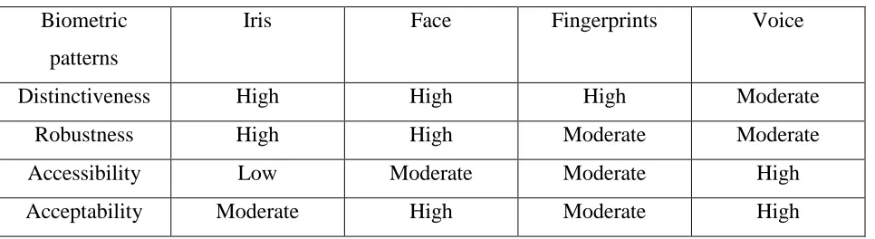
(Quatieri, 2002). It is a system of identifying or recognizing the identity of a living person based on physiological or behavioral characteristics. If the Biometric needs to be success in the security system, Biometric should have the uniqueness where different people have its own traits like the DNA of humans. Nengheng, (2005) has come out with a comparison of some Biometric Identification and classify the patterns into the following classification in Table 1:
Distinctiveness: characteristic in pattern among population
Robustness: repeatable, not subject to large changes
Accessibility: easily presented to sensor
[image:4.612.68.551.341.473.2]Acceptability: perceived as non-intrusive by users
Table 1: Comparison Between Biometric Identification
Biometric patterns
Iris Face Fingerprints Voice
Distinctiveness High High High Moderate
Robustness High High Moderate Moderate
Accessibility Low Moderate Moderate High
Acceptability Moderate High Moderate High
From the Table 1, it shows that the biometric patterns of voice are both high accordance with accessibility and acceptability. But for distinctiveness and robustness, it is moderate. Actually, the security measures three different goals that are:
Protect the confidentiality
Protect the integrity
The availability of data for authorized use
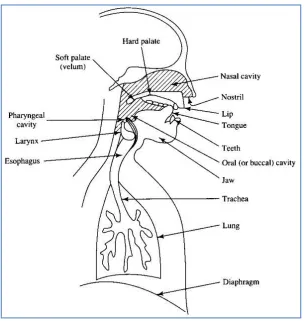
According to Syahrizat, (2009) the specific characteristics of speaker speech are due to difference in the aspect of speech production system in human body. The main aspect of speech production system is the vocal tract shape which is showed in Figure 1. It is generally considered as speech production organ above the vocal folds. The vocal folds consist of:
i) Laryngeal pharynx – beneath the epiglottis
ii) Oral pharynx – behind the tongue, between epiglottis and velum
iii) Oral cavity – forward of the velum and bounded by lips, tongue and palate. iv) Nasal pharynx – above the velum, rear end of nasal cavity
[image:5.612.155.460.275.596.2]v) Nasal cavity – above the palate and extending from pharynx to the nostrils.
Figure 1: Vocal tract of speech production system
1.2Problem Statement
The common problem with identification system nowadays is that the system can easily be fooled. Although it uses biometric identification which is unique from everyone else, there are still ways to fool the system. As for fingerprint identification, it does not have a good psychological effect on the people because of its wide use in crime investigations. Also, when the surface of human fingerprint is hurt, the recognition system will have problems to recognize the user because the system recognizes the surface of the fingerprints while for face recognition,
people are still working the pose and the illumination invariance. Manjot, (2003) explained that the performance of speaker identification system can vary according to the quality of the audio signal and the time taken to record the audio signal. During the recording, the time taken to record should be suitable. If it is too short, it will result in lack of identifying enough data. If it is too much time, it will reduce the accuracy of system. Background noises also play an important issue to be overtaken. The software will have a slightly problem of identifying voices signal when there are too many noises. To overcome this problem, the noise has to be filter so that any unwanted signal is removes. There are also measurements of energy levels compared to energy levels of silence. It will enhance the process of identifying the signal voices.
1.3Objectives
There are three main objectives in this research. There are:
To provide identification access control.
To design Biometric Speaker Identification System.
1.4Scopes of project
1.4.1 Data
This project focuses on developing a system that uses the speech signal as a recognition system. The speech signal will be recorded using microphone. There are 10 speakers. 5 of them are male and the rest are female. The signal is text dependent, where speakers will utter the words which will be described in the following chapter. Different speaker will generate different
speech waves.
1.4.2 Tools
The main tools that are use in this research is MATLAB software. The MATLAB DSP (Digital Signal processing) toolbox is also use to develop the programs in the software.
1.4.3 Hardware
The hardware that has been used in this research is: 1. Laptop
2. Intel Pentium Core 2 Duo 1.6Ghz
3. USB PC Microphone
1.5Thesis Outline
The first outline of the research is introduction. The introduction describes what this
project is all about. Aside from that, are defining suitable objectives and scopes for this project, deciding method to conduct the project and develop plan of the project. Chapter II deals with the
CHAPTER II
LITERATURE REVIEW
2.1Introduction
There are a few types of similar system has been developed by other researcher. Each system has its own method as well as advantages and disadvantages. They also depend on how the mechanism works. Each system has the same purpose. The purpose is to provide medium security system based on Biometric Recognition, or in this paper it is known as Voice Recognition as the access key. It is a process of automatically recognizing who is speaking on the basis of individual information. The system uses physical characteristics and traits on human being which are unique for the recognition of the individuals. Using the information, the system makes it possible to use speaker’s voice to verify their identity and control access.
2.2Technology Developments
According to Cui and Xue (2009), recognition is classified as talker recognition and voice recognition. The talker recognition also can be classified as relevant to text or irrelevant to text. For voice recognition system, the user needs to pronounce according to the stated contents. It is
easy to build up models. For voice recognition that is irrelevant to text, the user does not need to pronounce contents of the talkers. It is hard to build up models.
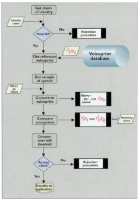
rejecting the identity claim of speakers. It authenticate that a person is who she or he claim to be. This technology can be used as a biometric feature for verifying the identity of a person in an application like banking by telephone and voice mail. Figure 2 shows the flowchart of speaker verification.
Figure 2: Speaker Verification
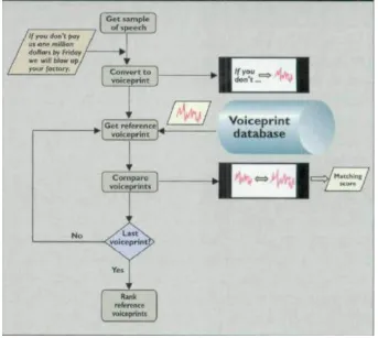
Speaker recognition can be divided into two types. It is called as dependant and text-independent. Text-dependant will identify specific words that the speaker will speak or sentences having the same text both for training and recognition trials. While text-independent will identify speaker regardless of what they are saying. It does not rely on specific words that being speak. (Lasse and Kasper, 2005). Figure 3 shows the flowchart of speaker identification.
Figure 3: Speaker Identification.
2.3Removing Background Noise
signal. It is because of complexity of voice signal and limitation in the scope of voice coding systems. Therefore, it is important to have a method for removal of background noises. According to Rozeha and Adib (2008), the removal of background noises or any unwanted signal can be done by passing it through Digital Filter Design block in MATLAB (SIMULINK) software shown in Figure 4, which serves as digital IIR band-pass filter.
Figure 4: Digital Filter Design block
Another method to remove background noise from voice recognition signal is by using spectral subtraction method. Udrea and Coichina (2003) defines the basic principles of spectral subtraction method is to subtract the short term spectral magnitude of noise from the signal. Average signal and average noise are estimated and subtracted from each other. This will make signal to noise ratio improved. The following equation will define more about spectral subtraction method.
(2.1)
Where:
= the noisy signal
= sum of desired signal
= the noise
So, in order to get the desired signal,
Where:
= the desired signal
= noisy signal
= the noise
Speech signal can be improved by passing the signal through low-pass filter and use Fourier method for processing the signal. The processing of digital signal can be divided into FIR (finite-impulse response) and IIR (infinite-impulse response). FIR is a non-recursive filter where it has an output that is a function of input samples and is not a function of previous output samples. A recursive filter has an output that is a function of an input samples and previous output samples. In general, FIR filter have better performances in analyzing the signal but
execute slower because the process of Fast Fourier Transform takes a longer time. The IIR filter on the other hand executes faster but has low performances. (B. Gold and N. Morgan, Speech and Audio Signal Processing).
Commonly, filters are designed to be low-pass (passing frequencies below some cut-off point). Darren (2001) in unpublished thesis on Design of Speaker Recognition has proposed a method in removing background signal. First, signal will converted to frequency domain through the use of a shifted FFT. Then, using 3rd order Butterworth low-pass filter which is also an IIR filer, the higher frequency signal will be removed. The cutoff frequency is chose to remove as much of noise signal while still preserving the original shape of the signal. The equation of Butterworth low-pass filter is as follows:
(2.3)
Where:
= rms value of signal
= cutoff frequency
However, Shonda and Simon (2003) stated that Fourier method only details the spectral content of a signal in frequency domain. Using the Fourier transformation, the time domain information for a particular event is lost because preservation of time instances is not considered. This condition can be overlooked if the signal is stationary. However, the speech signal is non-stationary signal. It can be classified as information carrying non-non-stationary acoustic signals.
Shonda and Simon (2003), proposes Wavelet analysis as another alternative method to overcome the problem. Wavelet uses the concept of multi-resolution analysis to produce precise
decompositions of signals for accurate signal representation. Detail characteristics like small discontinuities, self-similarities and higher order derivatives can be revealed. Other than that, Wavelet is also a nonlinear function and do not remove noise by low-pass filtering like many traditional method. The approaches of low-pass filtering, which is also a linear time invariant, can blur the sharp features in signal and sometimes difficult to separate noise from the signal where the Fourier spectra overlap. The threshold of the Wavelet coefficients can remove the noise. This is because the signal that has energy concentrated in a small number of Wavelet coefficients, their values will be large in comparison of the noise. The process allows features in the original signal remain sharp. The disadvantages of using Wavelet denoising is the lack of shift-invariance, means that the Wavelet coefficients do not move by the same amount that the signal is shifted. But the problem can be overcome by averaging the denoising result over all possible shift of the signal. The process of noise reduction using wavelet coefficients threshold can be obtained in MATLAB command wdencmp. The equation of Wavelet coefficients can be obtained in equation below:
(2.4)
Where:
= wavelet representation
= basic function called daughter wavelet where , , and as dilation, translation
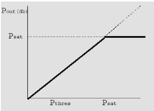
After finishes the process of noise reduction using Wavelet coefficients, the process of amplitude compression will take over. Fundamentally, it is a task of controlling the overall gain of speech amplification system. Amplitude compression will check bit by bit, that output power will not exceed a given saturation level, Psat. The filter will remove a significant amount of noise if the values exceed saturation level. So, the process of amplitude compression will ensure the amplified signal will not exceed saturation level, where the sound of speech begins to become uncomfortable. The process is shown in Figure 5 below.
Figure 5: The value will not exceed saturation level.
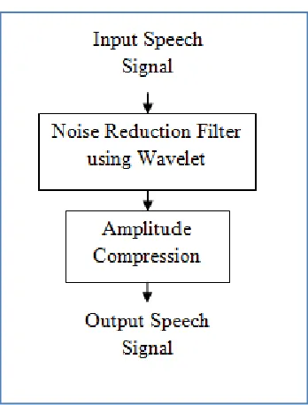
Figure 6: Flowchart of removing background noise
2.4Feature Extraction
After the process of removing background noises from voice signal has finish, the process of feature extraction will begun. Kesarkar (2008) explains that feature extraction is a process of obtaining different features of voice signal such as amplitude, pitch and the vocal tract. It is a task of finding parameter set obtained from the input voice signal. Lasse and Kasper, 2005 has stated that extracted features should have some criteria in dealing with the speech signal such as:
Stable over time
Should occur frequently and naturally in speech
Should not be susceptible to mimicry
Easy to measure extracted speech features
Shows little fluctuation from one speaking environment to another
Discriminate between speakers while being tolerant of intra speaker variabilities
with a nonlinear frequency axis following mel scale. To obtain mel cepstrum, the voice signal is windowed first using analysis window and then Discrete Fourier Transform is computed. The main purpose of MFCC is to mimic the behavior of human ears. Figure 7 shows the block diagram of MFCC.
Figure 7: Block diagram of MFCC
2.4.1 Frame Blocking
Frame blocking will blocked the continuous speech signal into frames of N samples, with adjacent frames being separated by M (M<N). First frame consists of first N samples. Then, second frame begins with M samples after the first frame, and overlaps it by N-M samples and so on. This continues until all the speech is accounted within one or more frames.
2.4.2 Windowing
The next step in the processing is to window each individual frame so as to minimize the signal discontinuities at the beginning and end of each frame. The concept here is to minimize the spectral distortion by using the window to taper the signal to zero at the beginning and end of
each frame. If we define the window as w(n),0 n N 1, where N is the number of samples
in each frame, then the result of windowing is the signal
Typically the Hamming window is used, which has the form:
(2.6)
2.4.3 Fast Fourier Transform
The next processing step is the Fast Fourier Transform, which converts each frame of N samples from the time domain into the frequency domain. The FFT is a fast algorithm to
implement the Discrete Fourier Transform (DFT), which is defined on the set of N samples {xn},
as follow: 1 0 / 2 1 ,..., 2 , 1 , 0 , N n N kn j n
k x e k N
X
(2.7)
In general Xk’s are complex numbers and we only consider their absolute values
(frequency magnitudes). The resulting sequence {Xk} is interpreted as follow: positive
frequencies 0 f Fs/2 correspond to values 0 n N/2 1, while negative frequencies
0 2
/ f
Fs correspond to N/2 1 n N 1. Here, Fs denotes the sampling frequency.
The result after this step is often referred to as spectrum or periodogram.
2.4.4 Mel-frequency Wrapping
As mentioned above, psychophysical studies have shown that human perception of the frequency contents of sounds for speech signals does not follow a linear scale. Thus for each
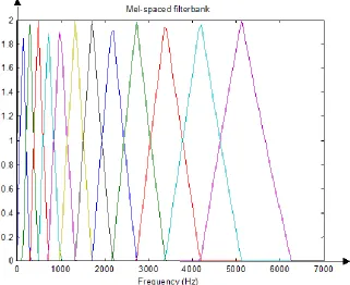
tone with an actual frequency, f, measured in Hz, a subjective pitch is measured on a scale called the ‘mel’ scale. The mel-frequency scale is a linear frequency spacing below 1000 Hz and a
Figure 8: Example of mel-spaced filterbank
One approach to simulating the subjective spectrum is to use a filter bank, spaced
uniformly on the mel-scale (see Figure xx). That filter bank has a triangular bandpass frequency response, and the spacing as well as the bandwidth is determined by a constant mel frequency interval. The number of mel spectrum coefficients, K, is typically chosen as 20.
2.4.5 Ceptrum
In this final step, we convert the log mel spectrum back to time. The result is called the mel frequency cepstrum coefficients (MFCC). The cepstral representation of the speech spectrum provides a good representation of the local spectral properties of the signal for the given frame analysis. Because the mel spectrum coefficients (and so their logarithm) are real numbers, we can convert them to the time domain using the Discrete Cosine Transform (DCT). Therefore if we denote those mel power spectrum coefficients that are the result of the last step
1 ,..., 2 , 0 , ~
0 k K
S , (2.8)
we can calculate the MFCC's, ~cn, as
(2.9)
Note that we exclude the first component, ~c0, from the DCT since it represents the mean value
of the input signal, which carried little speaker specific information.
2.5Feature Matching
Rabiner and Juang, 1993 has explained that feature matching is a classification procedure to classify objects of interest into one of a number of categories or classes. There are a lot of feature matching techniques used in speaker recognition such as Dynamic Time Wrapping (DTW),
Hidden Markov Modeling (HMM), and Vector Quantization. Each technique will be previewed in section below.
2.5.1 Dynamic Time Wrapping (DTW)
One of the techniques in feature matching is Dynamic Time Wrapping (DTW). This technique is based on Dynamic programming where the algorithm is for measuring the similarity between two time series which may vary in time or speed. It is also used for optimal alignment between two times series if one time series may be ‘warped’ non-linearly by stretching or
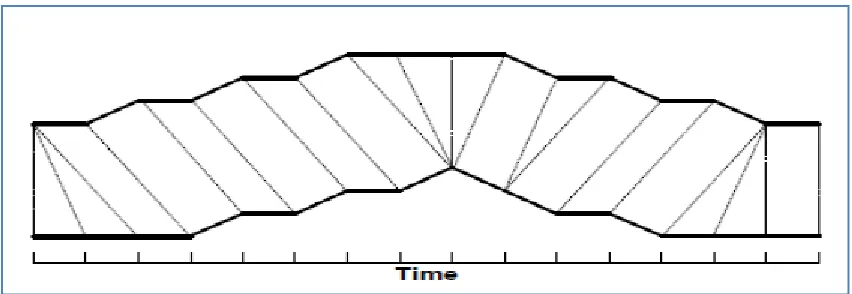
shrinking it along its time axis. Then, the similarity or corresponding regions between two time series can be found by warping between the two time series (L. Muda, M. Begam and I. Elamvazuthi, 2010). Figure 9 shows the process of one times series is ‘warped’ to another.
K-1 n K k n S c K k k
n , 0,1,...,
Figure 9: Warping between two times series.
Each vertical line in Figure 9 connects a point in one times series to its corresponding similar points in other time series. Actually, in y-axis the lines have similar values but have been separated so that vertical lines between times can be viewed more easily. We can see that when both the time series are identical, all the lines would be straight vertical lines because no warping would be necessary to line up the two time series. A measure of the difference between two time series after they have been warped together is called as the warp path distances, measured by the sum of the distances between each pair of points connected by the vertical lines.
The principle of DTW is to compare two dynamic patterns and measure its similarity by
Figure 10: Dynamic Time Wrapping
Consider the computation below. Suppose there are two time series Q and C, of length n and m respectively.
(2.10)
(2.11)
Using DTW, two sequences is aligned by an n-by-m matrix where the (ith,jth) element of matrix contains the distance d (qi,cj). Then, using Euclidean distances the absolute distance between the values of two sequences is calculated using equation:
(2.12)
search space for the input time to template time mapping function. The search for minimum distance path can be done using the equation below:
(2.13)
Where:
= minimum distance path
= length of sequence
= number of template to be considered
2.5.2 Hidden Markov Modeling (HMM)
Ibrahim Patel and Y. Srinivas (2010) explained that Hidden Markov Modeling (HMM) is a stochastic finite state automation defined by the parameter:
(2.14)
Where:
= stochastic finite number A = state transition probability p = initial state probability
[image:23.612.77.545.554.671.2]B = emission probability density function of each state
Figure 11 shows each model can be used to compute the probability of observing a discrete input sequence O = O1, …., OT, P(O|λ) to find the corresponding state sequence that maximizes the probability of the input sequence, P(Q|O, λ) and to induce the model that maximizes the probability of a given sequence P(O|λ) > P(O|λ).
Given the form of HMM in Figure xx, there are three basic problems to be solved:
1. Calculation of probability P(O|λ) for a given observation sequence
For this problem, the calculation for probability of occurrence for a given feature is one of the difficult and time consuming task. The probability is given by:
(2.15)
2. For a given observation sequence O = O1, O2, …, OT and a model λ, the selection to corresponding state sequence Q = q1, q2, qT which best explains the observation, is one more problem faced in speech recognition for HMM. The problem can be solved using Viterbi algorithm
3. For a given λ, the HMM parameters should be chosen to maximize the probability P(O|λ)
called a learning procedure. Considering all the temporal feature values as continuous using the continuous density HMM can optimize the learning process.
To measure the distance function d(i,j), the formulas is given with the assumption that the similar speech forming one cluster is corresponds to one HMM model.
2.5.3 Vector Quantization
[image:25.612.191.419.240.491.2]Speaker identification has been done successfully using Vector Quantization (VQ). Manjot, 2003 explained that it is a process to characterize speaker specific features by extracting a small number of representative feature vectors. It is then clustered to form a specific speaker codebook. Vector Quantization is also a lossy data compression method based on principle of block coding. It has fixed to fixed length algorithm. (Md Rashidul Hasan, 2004). Figure 12 shows the 2-dimensional of Vector Quantization.
Figure 12: 2-dimensional VQ.
Figure 13: Conceptual diagram of VQ
Only two speakers and two dimensions of acoustic space are shown in the Figure 13 above. Acoustic vector from speaker 1 is illustrated by circles while the triangles are from speaker 2. A speaker specific VQ codebook is generated in the training phase using Linde, Buzo and Gray (LBG) clustering algorithm. The result codewords (centroids) are shown in Figure 13 by black circles and black triangles for speaker 1 and 2, respectively. VQ distortion is the distance from a vector to the closest codeword of a codebook. The speaker corresponding to the VQ codebook with smallest total distortion is identified as the speaker of the input utterance.
2.6Clustering the Training Vectors