Journal of Chemical and Pharmaceutical Research, 2013, 5(9):381-387
Research Article
CODEN(USA) : JCPRC5
ISSN : 0975-7384
Dynamic analysis and test study of ultrasonic compound micro-fine
electrical-machining system
Zhu Yongwei, Shao Jian and Chen Hongzhen
Institute of Mechanical Engineering, Yangzhou University, Yangzhou, China
_____________________________________________________________________________________________
ABSTRACT
The dynamic performances of ultrasonic vibration system are the key facts decided the manufacturing precision of the ultrasonic compound micro-fine electrical-Machining, that is ultrasonic compound micro-fine EDM&ECM (electro-discharged machining and electrochemical machining). The finite element method is used to analyze the dynamic performance of the ultrasonic vibrating system, the finite element analysis package ANSYS is applied to optimize the structure design of the piezoelectric transducer vibration system. A serious of optimization tests are carried about the ultrasonic compound micro-fine electrical-Machining, a few of micro-fine structures are machining by the optimization processing parameters. It is proved that the system's optimization designing can improve the machining performances by increasing machining process's reliability and stability, and the ultrasonic compound micro-fine electrical-machining would have better machining precision and higher productivity for to machine the materials difficult to machining and the special shape's structures.
Keywords: Ultrasonic vibration system, ANSYS analysis, Optimal design, EDM & ECM, Micro-fine machining
_____________________________________________________________________________________________
INTRODUCTION
Ultrasonic machining (USM) and ultrasonic compound electrical-machining technologies are very effective for to machine the materials with the high brittleness, the high hardness and the special complex surface[1,2]. Ultrasonic vibration system is the chief part of ultrasonic compound micro-fine electrical-machining, it is made up of ultrasonic transducer, amplitude transformer and the tool[3]. The system must have good dynamic performance, which can make it work more effectively, stably and ensure the accuracy requirements of component parts being machined. The dynamic performances including the natural vibration characteristic analysis and the harmonic analysis are researched in this paper[4]. The design requirements of ultrasonic transducer are the high electro-mechanical transfer coefficient[5,6] and the high amplitude of the end. For amplitude transformer, it must maximize the amplification factor within the permissible stress. So the electromechanical transfer coefficient, the high amplitude, amplification factor, resonant frequency can be used as optimal objective. The parametric optimization design technique of the finite element analysis package ANSYS is applied to optimize the structure dimension of the piezoelectric transducer and transformer with tool. Then amplitude of the optimized system and the previous system is compared based on Laser-CCD sensor for micro-displacement. Using the optimized system and the optimization processing parameter, a serious of ultrasonic compound micro-fine electrical-machining tests are carried, a few of precise micro-structures are machined ,which are difficult to machining by traditional mechanical machining way.
1. ULTRASONIC MICRO-FINE ELECTRICAL MACHINING SYSTEM
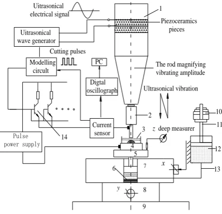
Fig.1 Ultrasonical Compound micro Electro -discharged and Electrolytic Machining System
The rod magnifying vibrating amplitude can enlarge the vibrating amplitude, and connects with the energy transformer by screw thread, micro-electrode connects with the screw hole of rod magnifying vibrating amplitude, and connected surface is full of plant oil for to decrease energy losses. The rod magnifying vibrating amplitude makes the electrode doing ultrasonic frequency vibrating, when starts, the frequency should be adjusted achieving resonance, the vibrating amplitude will get maximum value, and this can be adjusted by the ultrasonical power.
The modeling circuit generates cutting pulse by the ultrasonical wave signal, the cutting pulse will turn on or turn off the power supply, the synchronization target of micro-machining with ultrasonical vibrating may be realized, machining accuracy can be improved further[6]. The pulse power supply positive role connects with tool electrode; the negative role connects with the micro workpiece. Definite micro-pressure remains between workpiece and cathode, the micro-pressure can be adjusted fine by the balance weight. Connector oil transmits pressure, ensuring the cathode and micro-workpiece contacts with stable micro-pressure (0.30N ~5.0N).
DYNAMIC ANALYSIS
The design values of amplitude transformer are as follows. The material is carbon steel c45. The working frequency is 20000Hz. The two end’s diameters are 52mm and 16mm respectively. The value of density, elastic modulus, poison ratio is 7800 kg/m3, 20800kg/mm2 and 0.28 respectively according to the characteristic of carbon steel c45.
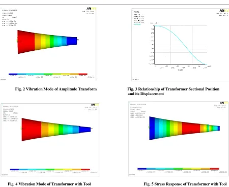
The paper sets Block Lanczos for the method of modal extracting and the number of modal extracting is seven. FEA result shows that the first seven frequencies are 14265Hz, 14467Hz, 14471Hz, 19685Hz, 24342Hz, 24501Hz, 24510Hz. Extract one step natural frequency which is close to the working frequency. Displacement vector of all nodes are aligned along the axis when the frequency is 19685Hz . So, it is concluded that natural frequency of transformer is 19685Hz. When carrying on harmonic analysis, 0.005mm displacement is exerted on the big end of transformer along the X-axis. On this condition, the displacement of the small end is 0.0162mm as is shown in Fig. 2. So the amplitude magnifies 3.24 diameters. Node is located next to the big end about 56.1mm as is shown in Fig. 3. If having modal analysis on transformer with bolt, the result shows that the resonant frequency is almost the same to transformer. If having modal analysis on transformer with tool, the FEA result reveals that natural frequency is 17926Hz, it is shown in Fig.4.
The rod magnifying vibrating amplitude Ultrasonical vibration 13 12 11 10 4 9 8 6 7 5 3 2
zdeep measurer
______________________________________________________________________________
[image:3.595.75.526.59.427.2]
Fig. 2 Vibration Mode of Amplitude Transform Fig. 3 Relationship of Transformer Sectional Position and its Displacement
Fig. 4 Vibration Mode of Transformer with Tool Fig. 5 Stress Response of Transformer with Tool
Compared with the modal result of transformer, the resonant frequency has reduced 1759Hz. The maximum response stress is 51.3MPa(see Fig. 5), which is much less than the permissible stress[7]. Also, the result shows that the magnification of it is 3.94, which is bigger than 3.24.
[image:3.595.119.493.524.574.2]Performance parameters of transformer by theoretic calculation and FEA are compared in Table 1.
Table 1 Comparative study on performance parameters of transformer
Transformer Transformer with tool
Magnification Joint Displacement[mm] Magnification Joint Displacement[mm]
Theoretic Calculation 3.25 53.6 3.89 58.4
FEA 3.24 56.1 3.94 60.1
Deviation 0.308% 4.664% 1.285% 2.911%
OPTIMAL DESIGN
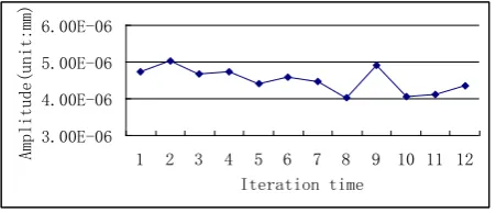
The fundamental parameters of transducer are as follows. Diameter of transducer is 50mm. Size of piezoelectric ceramics, electrode is Ф52×6mm and Ф52×0.03mm respectively. The material of electrode is Cu. LY12 is for front plate and carbon steel c45 is for back plate. The type of piezoelectric ceramics is PZT4.The length of back and front plate is design variable in this paper. Set L1 for the length of front plate and L2 for back plate. By changing L1 and L2, the amplitude of piezoelectric transducer within certain frequency can be optimized to the largest. The range of L1 is from 0.045m to 0.8m. The range of L2 is from 0.025m to 0.045m. The reciprocal of amplitude is the objective. F is state variable in this paper. And the range is from 19000Hz to 21000Hz. The following is optimum sequence marked with “*”.
Fig. 6 Relationship between Iteration time and Amplitude
[image:4.595.194.420.131.228.2]The natural frequency will be decreased by a certain extent when transformer is connected with tool. The resonant frequency can be raised by decreasing the length of transformer[8]. The paper adopts the parametric optimization design techniques. The step of optimization is close to transducer.
Fig. 7 Parametric Design Model of Transformer with Tool
Parametric design model of transformer with tool is shown in Fig. 7. The design variables are TK18, TK29, TK310, TK411, TK512 and L. L ranges from 0.12m to 0.16m. The rest range from 0.008m to 0.03m. F and maximum max_eqv are state variables. F ranges from 18000Hz to 21000Hz. Max_eqv ranges from 0 to 480MPa. The reciprocal of amplitude is the objective. The following is optimum sequence marked with “*”.
*SET 8* (FEASIBLE) F (SV) 19621. YL (SV) 6.2725E 07 TK18 (DV) 0.28013E-01 TK29 (DV) 0.22537E-01 TK310 (DV) 0.18162E-01 TK411 (DV) 0.13941E-01 TK512 (DV) 0.10753E-01 L (DV) 0.12135 S (OBJ) 3.0555
According to the above sequence, resonance frequency is 19621Hz. The length of it is 121.35mm and the amplitude is 0.0327mm.
TEST OF VIBRATION SYSTEM
The system is composed of USM machine tool, index transformer, Laser-CCD sensors for micro-displacement, personal computer and so on. Device connecting is shown in Fig. 8. Test result is shown in Fig. 9.
3.00E-06
1 2 3 4 5 6 7 8 9 10 11 12
Iteration time
Amplitude(unit:mm)
1 2 3 4 5 6 7 8
9 10
11 12 13
15 14 TK18
L
______________________________________________________________________________
Fig. 8 Device Connecting
Fig. 9 Display Image of Micro-displacement
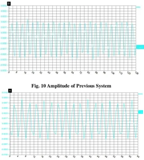
The following is the result. The amplitude of vibration system prior to optimization is 0.0025mm as is shown in Fig. 10. The amplitude of optimized system is 0.008mm as is shown in Fig. 11.
[image:5.595.203.407.69.360.2]
Fig. 10 Amplitude of Previous System
Fig. 11 Amplitude of Optimized System
[image:5.595.192.422.418.674.2]
(a) Ring Slot Processing without Mixing Powder (b) Ring Slot Processing Mixing micro Diamond Powder
Fig. 12 Ring Slot Machined by Ultrasonical Compound Micro-discharge and Electrolytic Method
The processing depth of is up to 500μm or more, good forming precision is acquired; it can be shown in Fig. 12 (b).
6.2 Machining micro gear of Hard alloy YT15
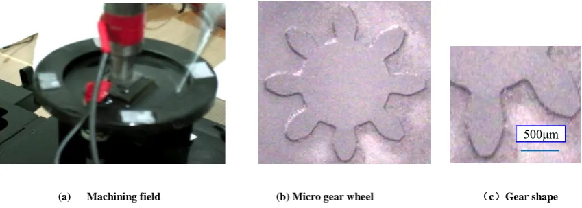
DC voltage amplitude 3V, the resonance frequency of ultrasonic vibration system is 17.46KHz, ultrasonic vibrating amplitude is 0.09mm, the fine static pressure between the workpiece and the cathode is 3.0N, working solution is 2% NaNO3 water solution mixed with 60% alcohol solution , mixed by micro-powder of W5-B4C, processing time is 5 minutes. Using the ultrasonic compound discharge - Electrolytic processing method, Machining field is shown in Figure 13(a).
Fine electrode with an inner gear shape hole, m=0.25mm, Z=8, pressure angle α=20 º , workpiece material is hard alloy YT15, micro-machined gear thickness of 1.00 mm, gear shape accuracy up to 0.001mm, surface roughness is Ra 0.20μm.
Micro gear photos is shown in Fig.13(b), micro gear photomicrograph can be seen in Fig. 13(c)
DC voltage amplitude 3V, the resonance frequency of ultrasonic vibration system is 17.46KHz, ultrasonic vibrating amplitude is 0.09mm, the fine static pressure between the workpiece and the cathode is 3.0N, working solution is 2% NaNO3 water solution mixed with 60% alcohol solution , mixed by micro-powder of W5-B4C, processing time is 3 minutes. Using the ultrasonic compound discharge - Electrolytic processing method, Machining field is shown in Figure 13(a).
[image:6.595.148.434.186.321.2](a) Machining field (b) Micro gear wheel (c)Gear shape
Fig. 13 Micro gear photos of ultrasonical compound micro electro-discharged electrolytic machining
500μm
[image:6.595.81.506.598.749.2]______________________________________________________________________________
Fine electrode with an inner gear shape hole, m=0.25mm, Z=8, pressure angle α=20 º , the workpiece material is hard alloy YT15, micro-machined gear thickness of 2.00 mm, the gear shape accuracy is up to 0.001mm, surface roughness is Ra 0.20μm.
Micro gear photos is shown in Fig.13(b), micro gear photomicrograph can be seen in Fig. 13(c)
CONCLUSION
(1) Stress distribution and the deformation which are acquired in post-processing of ANSYS are more directly when having dynamic analysis on vibration system. FEM is an effective method of analyzing the system; the natural frequency will be decreased by a certain extent when transformer is connected with tool, but magnification is much bigger.
(2) The amplitude of the optimized system enlarges slightly based on the comparative tests. The parametric optimization design technique should to be study in a deep-going way because selection range of design variable could directly affect the result.
(3) Ultrasonical combined synchronizing micro-electricalsystem works reliably; adopting the low conductivity and the working fluid mixed micro diamond powder, the machining process can maintain good stability, so that micro-fine machining with high precision and high efficiency can be acquired easily.
Acknowledgements
This work was financially supported by China National Science Foundation (51075355, 51375428). The authors give cordial thanks for the organization.
REFERENCES
[1] Cao Fengguo, Zhang Qinjian. Electromachining & Mould, supplement, pp.25-31, 2005.
[2] Zhu, Yongwei, Wang Zhanhe , Fan Zhongjun, et al. Jixie Gongcheng Xuebao, vol.43, No.6, pp.186-197, 2010. [3] Zhang Cunxin, Yang Jixian. Cao Wenyan, Heat Treatment Technology and Equipment, vol.27, no.5, pp.17-20, 2006.
[4]Liu Jinchun, Zhao Jiaqi. Non-Traditional Machining, China Machine Press, Beijing :2004. [5] He Xiping, Gao Jie. Technical Acoustics, vol.25, no.1, pp.82-86, 2006.
[6] Zhu Yongwei , Wang ZhanheLi Hongying,Yun Naizhang. Chinese Mechanical Engineering, vol.19, no.17, pp. 1786-1792, 2008.
[7] Shao Yunqiu. Case Studies: ANSYS8.0 Finite Element Analysis, China Railway Publishing House, Beijing: 2004.