Computational Fluid Dynamics Analysis of Single
Pass Shell & Tube Heat Exchanger with Different
Orientation of Baffles and Without Baffles
Nishank Kumar Pandey1, Dr. Rohit Rajvaidya21
(M-Tech (Product Design & Engineering), Department of Mechanical Engineering, BUIT, Bhopal)
2
(Assistant Professor, Department of Mechanical Engineering, BUIT, Bhopal)
Abstract : - In this specific project an endeavor is design for CFD evaluation of Single Pass Shell & Tube Heat Exchanger with Different
Orientation of Baffles and Without Baffles with counter flow of fluid. In order to research the performance of the heat exchanger, hot
fluid was designed to flow inside the seven tubes and cold fluid flows through outer pipe & tube material using Copper as well as Brass &
Shell Material using Carbon Steel. The baffles utilized in heat exchanger are usually segmental baffles cut of 25%. The introduction of
baffles, force the fluid to have a turbulent flow, thus improving the heat transfer rate. The outcomes of heat transfer rate for flow of fluid
with vertical segmental baffle inside heat exchanger are in comparison with the heat exchanger without having baffles. The result of heat
transfer rate & pressure drop for flow of fluid for 00baffles is also compared with baffle at 300orientations. The flow of hot fluids at
different Reynolds number will carry out having fluid velocity of 1 m /s, 2 m /s and 3 m /s & the flow of cold fluids at Reynolds number will
carry out having fluid velocity of 1 m /s. The deviation of heat transfer coefficient & pressure drop at different baffle orientations as been
carried out by means of Fluent 14.5 simulation.
STHX is an indirect contact type heat exchange because it is made up of a series of tubes, through which one of
the fluids goes. They are traditionally used in oil refineries, chemical plants, petrochemical plants, natural fuel processing,
air-conditioning, refrigeration as well as automotive applications. Computational Fluid Dynamics (CFD) can very helpful to obtain visualize
the actual flow as well as temperature fields with in the shell side can simplify the assessment of the weaknesses. Different turbulence
models available in general purpose commercial CFD tools likes k-ԑ, K-ω as well as K-ω SST models. This literature review concentrates
on the value and effectiveness of k-ԑmodel in CFD evaluation and simulation.
Keywords: - Heat Transfer Coefficient, Shell-and-Tube Heat exchanger, CFD, Un-baffled, Baffle inclination angle, Segmental Baffle,
Reduced Pressure Drop.
I. INTRODUCTION
Heat exchangers have always been an important part to the
life-cycle and operations of many systems. A heat exchanger
is can be a device created for effective heat transfer from one
medium to different in order to carry and process energy.
Typically one medium is cooled while the other will be
heated. They’re widely utilized in petroleum refineries,
chemical plants, petrochemical plants, natural gas
processing, Air conditioning, refrigeration and also
automotive applications. One popular example of the heat
exchanger will be the radiator within a car, in which it
transfers heat from the water (hot engine-cooling fluid) in
the radiator to the air passing through the radiator. There are
Direct contact heat exchanger in which both media between
which heat is exchanged are in direct contact with each
other.
Indirect contact heat exchanger where both media are
separated by a wall through which heat is transferred so that
they never mix. Shell and tube type heat exchanger is an
indirect contact type heat exchanger as it consists of a series
connected with tubes, through which one of the fluids runs.
The shell can be a container forthe shell fluid. Usually, it’s
cylindrical in shape with the circular cross section, although
shells of various shapes are used in particular applications.
With this particular study E shell is considered, which a one
pass shell is generally. E shell is the most widely used
because of its low price and simplicity, and has got the
highest log mean temperature- difference (LMTD)
modification factor. Although the tubes may have single or
multiple passes, there is usually one pass on the shell side,
while the other fluid flows inside the shell over the tubes to
be heated or cooled. STHX in various sizes are widely used
in industrial operations and energy conversion systems. The
best possible thermal design of the STHX involves the
consideration of many interacting design parameters which
can be summarized as follows:
Process
1. Process fluid assignments to shell side or tube side.
2. Selection of stream temperature specifications.
3. Setting shell side and tube side pressure drop design limits.
4. Setting shell side as well as tube side velocity restrictions.
Mechanical
1. Selection of heat exchanger TEMA design and number of
passes.
2. Specification of tube parameters - size, layout, pitch and
material.
3. Setting upper and lower design limits on tube length.
4. Specification of shell side parameters –materials, baffles
cut, baffle spacing and clearances.
5. Setting upper as well as lower design limits in shell
diameter, baffle cut and baffle spacing.
Fig.1 Shell and tube heat exchanger along with baffles plate.
Shell-and-tube heat exchangers are designed and fabricated
based on the standards of the Tubular Exchanger
Manufacturers Association (TEMA). Heat exchangers are
utilized in many engineering purposes like energy generation,
waste heat recuperation, manufacturing sector,
air-conditioning, refrigeration, living space applications,
petrochemical sectors etc. Use of segmental baffles in a Heat
Exchanger result in high pressure drop which is undesirable
as pumping costs are directly proportional to the pressure
drop inside a Heat Exchanger. Therefore, lower pressure drop
Exchanger:-Table 1.1, Heat Exchanger Applications in Different Industries.
Industries Applications
Food and Beverages
Ovens, cookers, Food processing and also pre-heating, Milk
pasteurization, beer cooling and pasteurization, fruit juices and
syrup pasteurization, cooling or chilling the final product to
Desired temperatures.
Petroleum
Brine cooling, crude oil pre-heating, crude oil heat treatment, Fluid interchanger cooling, acid gas condenser.
Hydro carbon processing
Preheating of methanol, liquid hydrocarbon product cooling,
feed pre-heaters, Recovery or removal of carbon dioxide,
Production of ammonia.
Polymer
Production associated with
polypropylene, Reactor jacket cooling for that Production of polyvinyl chloride.
Pharmaceutical
Purification of water and also steam, For point of use cooling on
Water For Injection ring.
Automotive Pickling, Rinsing, Priming, as well as Painting.
Power
Cooling circuit, Radiators, Essential oil coolers, air conditioners and
Heaters, energy recovery.
Marine
Marine cooling systems, Clean water distiller, Diesel fuel
Pre-heating, central cooling, Cooling of lubrication oil.
II. COMPUTATIONAL FLUID DYNAMICS
Computational fluid dynamics (CFD) is the application of
computers and also numerical techniques to solve
complications involving fluid flow. CFD have been
successfully applied in several areas of fluid mechanics.
These consist of aerodynamics of cars as well as aircraft,
hydrodynamics of ships, flow through pumps and turbines,
combustion as well as heat transfer, chemical engineering.
Applications within civil engineering include wind loading,
vibration regarding structures, wind and wave energy,
ventilation, fire, explosion hazards, dispersal of pollution,
wave loading on coastal and offshore structures, hydraulic
structures for example weirs as well as spillways, sediment
transport. More specialist CFD applications include ocean
currents, climate forecasting, plasma physics, blood flow and
heat transfer around electronic circuitry.
This variety of applications is extremely
broad and also involves a variety of fluid phenomena. In
particular, the CFD techniques useful for high-speed
aerodynamics (where compressibility will be significant but
viscous as well as turbulent effects are often unimportant) are
very different from those used to solve the incompressible,
turbulent flows typical of mechanical and civil engineering.
Although a few elements of this course are widely applicable,
the focus is going to be on simulating viscous,
incompressible flow through the finite-volume method. Stages in a CFD
Simulation:-The primary stages within a CFD simulation
are:
Pre-processor: Creating the
model:-o Identify the method or equipment to
become evaluated.
o Represent the actual geometry of interest
utilizing CAD tools.
o Use the actual CAD representation to
produce a volume flow domain across the
equipment that contains the essential flow
phenomena.
o Create the computational mesh within the
[image:4.612.37.571.126.696.2]Solver:-o Identify and also apply conditions in the
domain boundary.
o Solve the actual governing equations for
the computational mesh using evaluation
software.
Post processor: Interpreting the
outcomes:-o Post-process the actual completed ways of
highlight results.
o Interpret the actual prediction to find out
design iterations as well as possible
remedies, if required.
III. LITERATURE REVIEW
E.Salehi et al. [1] evaluate the shell-side stream of STHX
utilizing experimental as well as theoretical techniques.
Experimental as well as numerical results are compared over a
wide range of Reynolds numbers (1,000 t o 1,000,000). The
most crucial results of this research are the following:
Comparison associated with temperature profile of
exchanger, along with and without baffles, shows
that baffles possess the vital role in heat transfer
rate.
The outcomes also show how the effect associated
with changing the quantity of baffles will be more
crucial than various the heights of baffles with
regard to heat transfer rate in the shell.
Increasing Reynolds number in shell-side leads to
the improve of heat transfer rate.
Reynolds number could be increased with the
addition of the quantity of baffles easier and along
with less cost as compared with increasing the
actual inlet velocity on the fluid.
D.P.Naik et al. [2] has a assessment associated with counter
flow shell & tube heat exchanger by means of entropy era
minimization technique. The design variables which can be
used to the shell & tube heat exchanger are usually tube
inside diameter, tube outside diameter, number of tubes,
baffle spacing as well as tube pitch etc. The analyses of those
design parameters are very important to the overall
performance of shell & tube heat exchanger. Shell & tube
heat exchanger overall performance has increased
significantly by means of minimization of entropy generation
number considering the various design variables. For the
reason that mass flow rate associated with shell side fluid
will increase, the entropy era number increases. Therefore we
can easily reduce this entropy era number by means of
reducing this mass flow rate of cold fluid by optimization. If
we change tube side area heat exchanger effectiveness also
change.
Kevin M. Lunsford et al. [3] possesses analyzed to improve
the heat exchanger effectiveness & advised increasing heat
exchanger performance via a logical number of steps. The
initial step considers when the exchanger can be initially
working correctly. The 2nd step looks at increasing pressure
drop if easily obtainable in exchangers with single-phase heat
transfer. Increased velocity leads to higher heat transfer
coefficients, which can be sufficient to enhance performance.
Next, a crucial evaluation in the estimated fouling factors
might be of interest. Heat exchanger performance could be
increased using periodic cleaning & fewer conservative
fouling factors. Finally, for several conditions, it might be
feasible to contemplate enhanced heat transfer by using
finned tubes, inserts, twisted tubes, or maybe modified
M.A.Mehrabian et al. [4] provides the comparison associated
with experimental data with estimations of regular
correlations for that overall heat transfer characteristics of an
double pipe heat exchanger and concluded that when heat
comes to this inner tube stream by means of an immersion
heaters. The overall heat transfer coefficients are usually
inferred in the measured data. The heat transfer coefficient
from the inner tube flow (circular cross section) will be
calculated while using the standard correlations. The heat
transfer coefficient from the outer tube flow (annular cross
section) is usually then deduced. Higher heat transfer
coefficients tend to be reported within the laminar flow
regime compared to the forecasts of standard correlations
intended for straight and also smooth tubes. The
Experimental results show how the outer tube side heat
transfer coefficients are usually smaller compared to inner
side heat transfer coefficients with a factor of almost 1.5 and
also 3.4 in counter flow as well as parallel flow deal,
respectively. The agreement with predictions is very good for
that counter flow arrangement, but not very good for this
parallel flow arrangement.
Sunil S. Shinde et al. [5] offers studied concerning the
performance Progress in Single phase Tubular Heat
Exchanger utilizing continuous Helical Baffles as well as
investigated that how the performance connected with tubular
heat exchanger could be improved by helical baffles rather
than conventional segmental baffles. The application of
helical baffles in heat exchanger minimizes shell side
pressure drop, pumping price, size, weight, fouling etc. as
evaluate to segmental baffle intended for new installations.
The helix changer type heat exchangers may save capital cost
along with operating and also maintenance cost and so
improves this reliability and availability of process plant in an
inexpensive way. For that helical baffle heat exchangers, the
ratios of heat transfer coefficient to help pressure drop are
higher than those of a conventional segmental heat
exchanger. Because of this the heat exchangers using helical
baffles can have a greater heat transfer coefficient while
consuming identical pumping power. It could be concluded
that proper baffle inclination angle provides an optimum
performance of heat exchangers.
Apu Roy, D.H.Das [6] the existing work have been carried
out using a view to predicting this performance of a shell and
also finned tube heat exchanger in the light connected with
waste heat recovery application. Energy obtainable in the exit
streams of much energy the conversion devices such as I.C
engine gas turbine and so on goes because waste, if not
utilized correctly. The performances of the heat exchanger
have been evaluated by utilizing the CFD package fluent
6.3.16 and the available values are compared with
experimental values. By thinking about different heat transfer
fluids the performance in the above heat exchanger may also
be predict. The effectiveness parameters of heat exchanger
such as effectiveness, overall heat transfer coefficient, energy
extraction rate etc, are already taken in this particular work.
IV. RESULT & DISCUSSION
The analysis of the 3D Model have been performed by Using
FLUENT ANSYS the actual Analysis performed by using
with different orientation of segmental baffles & without
having baffles. For evaluation the input data is static for both
types. During these Projects work various design
consideration of choice of tube material, development of
analytical model and analytical thing to consider
assumptions, procedure and input parameters. The
pressure drop and higher heat transfer coefficient. The
outcomes obtain for with segmental and without baffles in
FLUENT ANSYS. The FLUENT ANSYS Results have been
obtained for different orientation of segmental baffles &
without having baffles:- Dimension of a
STHX:-Parameter Dimension
Shell Diameter(mm) 207
Tube outside Diameter(mm) 19
Tube Pitch 50
Length of Tube (mm) 1500
Number of Tubes 7
Tube to Tube Clearance 31
Shell Length 1500
No of Baffles 5
No of Passes 1
Properties of
Fluid:-Parameter Symbol Unit Cold Water (Shell)
Hot Water
(Tube)
Fluid Water Water
Specific
Heat CP KJ/Kg.K 4.178 4.178
Thermal Cond. K W/m.K 0.615 0.615
Viscosity µ Kg/m.s 0.0013 0.0013
Prandtl 's No. Pr 5.42 5.42
Density ρ Kg/m3 998.2 998.2
MATERIAL
PROPERTIES:- MATERIAL PROPERTIES OF
STEEL:-Property Value
Density(×1000 kg/m3) 7.871
Poisson's Ratio 0.27-0.30
Thermal Conductivity(W/m-K) 59.5
Specific Heat (J/kg-K) 481
MATERIAL PROPERTIES OF
COPPER:-Property Value
Density(×1000 kg/m3) 8.960
Poisson's Ratio 0.34
Thermal Conductivity(W/m-K) 401
Specific Heat (J/kg-K) 385
MATERIAL PROPERTIES OF
BRASS:-Property Value
Density(×1000 kg/m3) 8.600 Poisson's Ratio 0.331 Thermal Conductivity(W/m-K) 115
Specific Heat (J/kg-K) 375 Boundary
conditions:-1) Temperature’s:
-Side ᵒC
Hot Fluid inlet Temp. (T1) 63
Cold Fluid Inlet Temp. (t1) 33
2)
Velocity:-Tube Side
Velocity
Shell Side
Velocity
1 m/sec 1 m/sec
2 m/sec 1 m/sec
Fig.1.1 Pressure of STHX with tube material using Brass
with 300 & 00 Baffles at different velocity in (m/sec).
Static Pressure at 30ᵒbaffles V=1 (m/s).
Static Pressure at 0ᵒbaffles V=1 (m/s)
Fig.1.2 Pressure of STHX with tube material using Brass at
without Baffles & different velocity in (m/s)
Static Pressure at without baffles V=1 (m/s).
Fig.1.3 Pressure of STHX with tube material using Copper
with 30ᵒ& 0ᵒBaffles at different velocity in (m/s).
Static Pressure at 0ᵒbaffles V=1 (m/s).
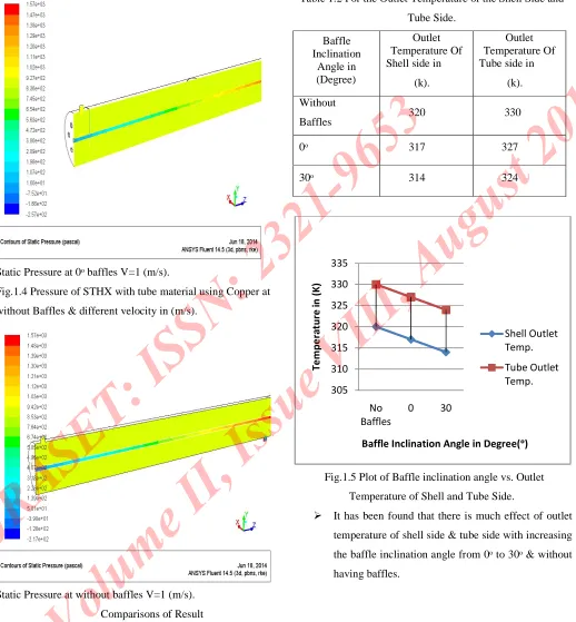
Fig.1.4 Pressure of STHX with tube material using Copper at
without Baffles & different velocity in (m/s).
Static Pressure at without baffles V=1 (m/s).
[image:9.612.48.566.114.673.2]Comparisons of Result
Table 1.2 For the Outlet Temperature of the Shell Side and
Tube Side.
Baffle Inclination
Angle in (Degree)
Outlet Temperature Of Shell side in
(k).
Outlet Temperature Of Tube side in
(k).
Without
Baffles 320 330
0ᵒ 317 327
30ᵒ 314 324
Fig.1.5 Plot of Baffle inclination angle vs. Outlet
Temperature of Shell and Tube Side.
It has been found that there is much effect of outlet
temperature of shell side & tube side with increasing
the baffle inclination angle from 0ᵒto 30ᵒ& without
having baffles.
305 310 315 320 325 330 335
No Baffles
0 30
Table 1.3 For the Pressure Drop Inside Shell.
Baffle Inclination Angle in
(Degree)
Pressure Drop Inside Shell (Pa)
Without Baffles 997.3923
0ᵒ 998.1241
30ᵒ 972.627
Fig.1.6 Plot of Baffle angle vs. Pressure Drop.
The shell-side pressure drop is decreased with
increase in baffle inclination angle i.e., as the inclination
angle is increased from 0° to 30°. The pressure drop is
decreased by 0.1 %, for heat exchanger without having baffle
and by 2.6 % for heat exchanger with 30° baffles inclination
compared to 0° baffle inclination shell & tube heat exchanger
as shown in fig. 1.6. Hence it can be observed with increasing
baffle inclination pressure drop decreases, so that it affect in
heat transfer rate which is increased.
Table 1.4 For Heat Transfer Rate across Tube side.
Baffle Inclination Angle in (Degree)
Heat Transfer Rate Across Tube side
(KW)
Without Baffles 4.41
0ᵒ 6.39
30ᵒ 8.52
Fig.1.7 Heat Transfer Rate vs. Baffle inclination angle.
1. The shell side of a small shell-and-tube heat exchanger is
modeled with sufficient detail to resolve the flow and
temperature fields.
2. The pressure drop decreases with increase in baffle
inclination.
3. The heat transfer rate is increase when the baffle
inclination is increase.
V. CONCLUSION
In this project, CFD evaluation of single pass heat exchanger
was done to evaluate the performance of the shell & tube type
heat exchanger with and without having baffles situated at
Outer pipe. The setup provides the following conclusions: Study of heat transfer in the heat exchanger at
different velocity.
950 960 970 980 990 1000 1010
No
Baffles 0 30
Baffles Inclination Angle in Degree (ᵒ) Series1
0 2 4 6 8 10
No
Baffles 0 30
The end result coming out from heat exchanger
having baffles located at outer pipe will be more
efficient via heat exchanger without having baffles. The outcomes of heat transfer coefficient coming out
by utilization of 30ᵒ baffles will be more efficient
than 0ᵒbaffles. As the angle of inclination increases,
the heat transfer rate of heat exchanger also
increases.
As the Reynolds number increases in the heat
exchanger, the heat transfer coefficient will increase.
VI. SCOPE OF FUTURE WORK
While using the CFD evaluation of Single Pass Shell & Tube
Heat Exchanger with Different Orientation of Baffles and
Without Baffles with counter flow of fluid, test runs is going
to be made for at least three different velocities (Reynolds
Numbers). The three different baffle orientations (i.e. 0ᵒ &
30ᵒ) will be studied for that corresponding velocity, inlet
temperatures, and counter flows resulting in total 150 test
runs. The analysis of heat transfer rate in heat exchanger can
be concluded by means of same baffle spacing. The
experimental results are compared with the CFD final results
and correlations will be developed with respect to these
conditions for that Nusselt number and other flow parameters.
REFERENCES
1) E. Salehi, S. Noie Baghban and M. Moghiman,
“Thermal evaluation of shell-side flow of shell &
tube heat exchanger using experimental and
theoretical methods”, International Journal of
Engineering, Vol. No. 13, pp. 13-26, February 2000.
2) D.P. Naik and V.K. Matawala, “An assessment of
counter flow shell & tube heat exchanger by entropy
generation minimization method”, World Journal of
Science and Technology, Vol. No. 2, pp. 28-32,
2012.
3) Kevin Lunsford, “Increasing heat exchanger performance”, Hydrocarbon Engineering, pp.1-13, (1998)
4) M.A. Mehrabian, S.H. Mansouri and G.A.
Sheikhzadeh, “The overall heat transfer
characteristics of a double pipe heat exchanger: comparison of experimental data with predictions of
standard correlations”, Archive of SID, Vol. No.15,
pp. 395-406, 2002.
5) Sunil S. Shinde, Samir S. Joshi and Dr. S. Pavithran,
“Performance Improvement in Single phase Tubular Heat Exchanger using continuous Helical Baffles”,
International Journal of Engineering Research and
Applications (IJERA), Vol. No.2, pp. 1141-1149, Jan
2012.
6) Apu Roy, D.H.Das, CFD Analysis Of A Shell &
Finned Tube Heat Exchanger For Waste Heat
Recovery Applications, National Institute Of
Technology, 2011.
7) Hamidou Benzenine, Rachid Saim , Said Abboudi &
Omar Imine, “Numerical analysis of a turbulent flow
in a channel provided with transversal waved baffles”, International Journal of thermal science, Vol. No. 17, pp. 1491-1499, 2012.
8) F.P. Incropera and D.P. Dewitt, “Fundamentals of heat and mass transfer”. 5th edition,
New York, USA: John Wiley & Sons; 2006.
9) B.K.P. Ary, M.S. Lee , S.W. Ahn and D.H. Lee, “The
transfer & flow patterns in the channel”, International communication
in heat and mass transfer, Vol. No. 39, pp. 1578-1583,
2012.
10) Ahmet Tandiroglu. “Effect of flow geometry parameters on transient heat transfer for turbulent flow in a circular tube with baffle insert", International journal of heat and mass transfer, Vol.
No. 49, pp. 1559-1567, 2006.
11) A. E. Zohir, “Heat Transfer Characteristics in a Heat
Exchanger for Turbulent Pulsating Water Flow with
Different Amplitudes”, Journal of American Science,
Vol. No. 8, pp. 241-250, 2012.
12) A.N. Mahure and V.M. Kriplani, “Review of Heat
Transfer Enhancement Techniques”,International
Journal of Engineering Research and Technology,