operator guide
Title: PICK Operator Guide
Document No. 88A00757A06
Date Revision Record
---+---Apr 83 Original Issue
Sep 83 Revision B - (Covering ZEBRA/PICK 2.0)
Apr 84 Revision A03
Oct 84 Revision A04
Feb 85 Revision A05 - Change Package (85A00514A01)
Apr 85 Revision A06 - Change Package (85A00520A01)
operator guide
88A00757 A06
Title: PICK Operator Guide
Document No. 88A00757A06
I
1 Date I Revision Record 1
---+---1
Apr 83 Original Issue
Sep 83 Revision B - (Covering ZEBRA/PICK 2.0)
Apr 84 Revision A03
Oct 84 Revision A04
Feb 85 Revision A05 - Change Package (85AOO514A01)
Apr 85 Revision A06 - Change Package (85AOO520A01)
FOREWORD
This manual provides operator guidance in the use of the General Automation ZEBRA/PICK operating system. It is intended for user persons responsible for standard day-to-day operations; and for user persons who must carry out the more specialized system operator functions. In today's computer environment. both of these may be in the hands of one person.
The major subjects arranged in that way are as follows:
Section 1 - Introduction
Section 2 - System Startup
Section 3 - Terminal Control Language
Section 4 - System File Management
Section 5 System Memory Management Section 6 - Dictionaries and Files
Section 7 Support Processors
Appendix A - ERRMSG (Error Messages)
Appendix B - ASCII Codes
Appendix C - ZEBRA Series Firmware Executives
Appendix D - Tape Operation
Related ZEBRA/PICK documents that are available to the user:
Document No.
88A0075lA
88A00758A
88A00759A 88A00760A 88A00774A 88A00775A 88A00776A 88A00777 A 88A00778A 88A00779A 88A00780A 88A0078lA 88A00782A 88A00783A
Title
Overview of the PICK Operating System
ACCD-PLOT Operator Guide
COMPU-SImET Operator Guide
Quick Guide for the PICK Operating System
PICK Utilities Guide
ZEBRA Hardware Reference Manual
PICK ACCESS Reference Manual
PICK SPOOLER Reference Manual
PICK BASIC Reference Manual
PICK EDITOR Reference Manual
PICK PROC Reference Uanual
PICK RUNOFF Reference Manual
Introduction to PICK TCL and FILE STRUCTURE
PICK JET Word Processor Guide
TMACCU-PLOT is a trademark of ACCUSOFT Enterprises
Section
1
2
3
TABLE OF CONTENTS
Title
INTRODUCTION • • • • • • 1.1
1.2" SYSTEM STRUCTURE • DICTIONARIES/FILES •
.
.
· .
. .
.
1.2.1 SYsrEK DICTIONARY (SYSTEM)·
.
.
1.2.21.2.3 USER MASTER DICTIONARIES (MD). PILE
LEVEL
DICTIONARIES. • • • • •·
.
.
.
.
.
.
·
.
. .
.
.
.
.
.
.
.
.
.
1.2.4 DAtA PILES • • • • • • •
· .
.
. · . .
.
1.3 FILE STRUCTURES ••.
.
.
1.3.1 FRAKES • • •
·
.
·
. .
.
. .
.
1.4
1.3.2 MODULO AND SEPARAtION.
. .
.
.
.
ITEM-ID
AND
AtTRIBUTES •·
. .
.
.
1.4.1 1.4.2
ItEM-ID • • • • • • • • ATTllIBUTES • • • • • •
1.4.2.1 Dictionary Attributes 1.4.2.2 Data Attributes • • • •
SYSTEM StARTUP • • • • •
2 .1 TUllNING ZEBRA ON • • • •
.
.
.
·
. .
2.2
2.1.1 ZEBRA 1500, 2500, 3500, 5500 • • • • • • • •
2.1.2
2.1.1.1 PICK Operating System Load • • • • ZEBRA 750. • • • • • • • • • • • • •
2.1.2.1 PICX Operating Systea Load • 2.1.2.2 -PICK OS RESTORE • • • • • • • 2.1.2.3
2.1.2.4
Binary Backup and RESTORE. BOOT • • • • • • •
2.1.2.5 Cartridge and Hard LOGGING OPERAtION • • • • • •
Disk Format Procedure
2.2.1 2.2.2 2.2.3
2.2.4 2.2.5
LOGON. • •
LOGOFF • • • • • • • • • • • ADDITIONAL LOGON FUNCTIONS • • 2.2.3.1 LOGTO • • •
2.2.3.2 CHARGE-TO.
2.2.3.3 CHARGES. • • • •
THE LOGON PROC AND GENERAL SYSTEM MESSAGES • POWERP'AIL AND GENERAL SYSTEM MESSAGE • • • •
TERMINAL CONTROL LANGUAGE (TCL). 3.1 TCL VERB TYPES • • • • • • • 3.2 TCL VERB ATTRIBUTES ••
·
. . .
. .
.
3.3 TCL VERB LIST. • • • • • 3.4 VERB DEFINITION FOR MD 3.5 TCL VERB STA'rEMEN'r • •
3.5.1 TYPE-I STATEMENTS •• 3.5.2 TYPE-II STA'rEMEN'rS •
Section 4 3.6 3.7 3.8 Title
TERMINAL/PRINTER CONTROLS • • • • • • • • • 3.6.1 KEYBOARD CONTROLS • • • • • • • • • 3.6.2 SETTING TERMINAL/PRINTER CONTROLS.
3.6.2.1 SET-TERM • • • • • • • • • • •
3.6.2.2 Cr~ng1ng Baud Rate (SET-BAUD)
3.6.3 3.6.4
SETTING TAB STOPS • • • • • • • • ENABLE/DISENABLE CHARACTER ECHO. 3.6.4.1 The ECHO Verb
3.6.5 BLOCK PRINTING • • • • 3.6.5.1 Block-Print. 3.6.6 GENERAL SERVICE VERBS.
3.6.6.1 TIME • • • • 3.6.6.2 WHO • • •
3 • 6 • 6 • 3 SLEEP. • • • • • •
.
.
.
3.6.6.4 MESSAGES. • • • • • • • •
TAPE OPERATION AND CARTRIDGE DISK: SET-1/2 (OR SET-MT), SET-1/4 (OR SET-CT), AND SET-CD • • • • • •
3.7.1 SETTING TAPE SIZE • • • • • • • • • • • • • • 3.7.1.1 Attaching Cartridge Disk • • • • • • 3.7.2 FULLY UTILIZING 1/4" TAPE BY LOCATING EOF'S:
T-EOF, T-EOFD • • • • • • • • PROGRAM INTERRUPTION: DEBUG FACILITY •
SYSTEM FILE MANAGEMENT • • • • • • • • • • • • • • • 4.1 CREATING NEW FILES: CREATE-FILE AND CREATE-PFILE •
4.2 CLEARING FILES • • • 4.2.1 CLEAR-FILE. 4.2.2 DELETE-FILE. 4.3 COPYING FILE DATA. • •
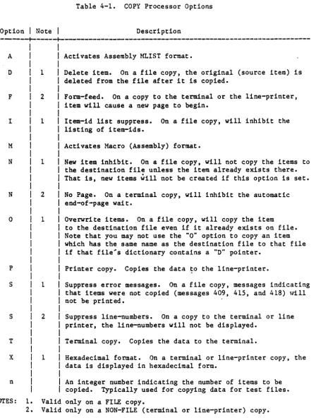
4.3.1 COPY PROCESSOR. 4.3.2 COpy OPTIONS •
4.4
4.5
4.3.3 FILE-TO-FILE COpy • • • •
4.3.3.1 Copy to Another Account • RESTORING FILE DATA. • • • • • • • • • • • • • 4.4.1 SELECTIVE RESTORES: SEL-RESTORE • • • • • 4.4.2 GROUP FORMAT ERROR • • • • • • •
4.4.2.1 Transient Format Error.
4.4.2.2 Real Format Error • • • • • • • 4.4.2.3 Recovery from Group-Error. 4.4.2.4 Preventing Group Format Error • SYSTEM FILE BACKUP • • • • • • • • • • • • 4.5.1 FILE-SAVE PROC • • • • • • • • • • • •
4.5.1.1 Customizing the FILE-SAVE PROC:
Section
5
Title
4.5.2 ACCOUNT-SAVE AND ACCOUNT-RESTORE • 4.5.2.1 ACCOUNT-SAVE PROC • • • 4.5.2.2 ACCOUNT-RESTORE • • • • 4.5.2.3 Multi-Reel Tape Operation.
SYSTEM MEMORY MANAGEMENT • • • 5.1 MEMORY STRUCTURE • • • • • •
5.1.1 ADDED WORK SPACE. 5.1.2 THE FILE AREA • • • 5.1.3 FRAME FORMATS • • •
.
.
.
.
.
.
5.1.3.1 Frame Format Display: DUMP
5.1.3.2 Frame Lock in Memory: LOCK-FRAME, UNLOCK-FRAME • • • • • • • • • 5.1.4 DISPLAY OF SYSTEM STATUS: WHAT, WHERE
5.1.4.1 The WHAT, WHERE Message. 5.1.5 LOADING AND USING SYSTEM SPACE.
5.1.5.1 POVF • • • • • • • 5.2 SYSTEM DICTIONARY AND SYSTEM FILE. • •
5.2.1 USER IDENTIFICATION ITEMS. • • •• 5.2.2 SYSTEM FILE AND SYSTEM-LEVEL FILES •
5.2.2.1 Accounting History File. 5.2.2.2 Block Convert File. • • 5.2.2.3 PROetIB File. • • • • • • •
.
.
5.2.2.4 SYSTEM-ERRORS File. • • • • •
5.3 SYSTEM-LEVEL FILES • • • • • • • • • •• 5.3.1 ACCOUNTING HISTORY FILE • • •
5.3.1.1 Active User Items •
5.3.1.2 Accounting History Items. • • • • • 5.3.1.3 Accounting History Pile Summary • • • • • 5.3.1.4 Accounting History File Clearance •
5.3.2 BLOCK-CONVERT FILE • 5.3.3 PROetIB FILE • • •• 5.4 ACCOUNT FILE MAINTENANCE • • •
5.4.1 CREATE-ACCOUNT PROC. 5.4.2 DELETE-ACCOUNT PROC. 5.4.3 POINTER-FILES.
5.5 BASIC PROGRAM FILE • 5.6 SYSTEM MESSAGES FILE •
'.
.
.
5.6.1 ERRMSG FILE. • • • • • • •
5.6.1.1 Special ERRMSG File Items. 5.6.2 PRINT-ERR VERB • • • • • • •
.
.
.
.
Section
6
Title
DICtIONARIES AND FILES • 6.1 FILE ACCESS • • • • 6.2 THE DICtIONARIES •
6.2.1 THE SHARING OF DICTIONARIES ••
6 .3 FILE STRUCTURE • • • • • • • • • • • •
6.4
6.5 6.6
6.7
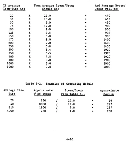
6.3.1 BASE, MODULO AND SEPARATION. 6.3.2 SELECTING MODULO AND SEPARATION. ITEM SnUCTUaE • • • • •
6.4.1 PHYSICAL • • • • • • • • • • • 6.4.2 L O G I C A L . . .
ITEM STORAGE AND THE BASHING ALGORITHM • •
.
.
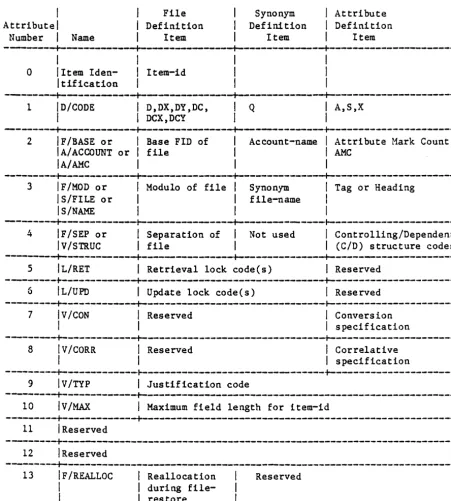
FILE ITEM SnUCTUBE. • • • • • • • • • • • • • • • • • • • 6.6.1 FILE DEFINITION ITEMS (D) • • • • •
6.6.2 FILE SYNONtK DEFINITION ITEMS (Q).
6.6.2.1 Q-Pointer Flexibility • • • • • 6.6.2.2 Account Specification • • • 6.6.2.3 File Specification • • • • • • 6.6.2.4 Extensions to File-Naae Reference • 6.6.3 AXTRIBUTE DEFINITION ITEMS (A) •
CONVERSION AND CORRELATIVE CODES •
6.7.1 THE ARITHMETIC CODE (A) • • • • • • • • • 6.7.1.1 Operands • • • •
6.7.1.2 FunctioDS • • • 6.7.1.3 Operators • • •
6.7.2 THE CONCATENATION CODE (C) • • • • • • • 6.7.3 THE DATE CODE (D) • • •
6.7.4 tHE FUNCTION CODE (F).
6.7.5 6.7.6 6.7.7 6.7.8 6.7.9 6.7.10 6.7.11 6.7.12 6.7.13 6.7.14
6.7.4.1 Special 'F' Code Operands.
6.7.4.2 The Load Previous Value (LPV) Operator •• 6.7.4.3 Summary of F Code Stack Operations.
THE GROUP EXTRAClIOtl CODE 'G' • • • • THE LENGTH AND RANGE CODES 'L', 'R' • • • THE MASK CHARACTER CODE 'MC' • • •
THE MASK LEFT AHD MASK RIGHt CODES 'ML', 'MA'.
tHE MASK tIME CODE .... MT'. • • • • • • • • • • • • •
THE MASK HEXADECIMAL CODE .... MX' • • • • • • • tHE PATTERN AND SUBStItuTE CODES 'p .... , 'S'. THE TEXT EXTRACTION CODE .... T' • •
tHE TRANSLATE FILE CODE 'Tfile' • • • • • THE USER-DEFINED CONVERSION CODE
'u' .
Section
7
Appendix
Title
SUPPORT PROCESSORS • • • • 7.1 UTILITY PROCESSORS
7.1.1 CT PROC • • •
.
.
.
.
. .
.
. .
.
.
7.2
7.3 7.4 7.5
7.1.2 LISTACC PROC • 7.1.3 LISTCONN PROC. 7.1.4 LISTDICT PROC 7.1.5 LISTFILES PROC • 7.1.6 LISTPROCS PROC •
7.1.7 LISTU PROC • • • • • • •
. . .
.
.
7.1.8 LISTVERBS PROC • SYSTEM SECURITY • • • • • • • 7.2.1 LIRET AND L/UPD • • •
.
.
. . .
.
.
.
.
7.2.2 USER ASSIGNED CODES.7.2.3 SECURITY CODE COMPARISON
FILE STATISTICS REPORT • • • • • • • • FILE CHANGE VERIFICATION (CHECK-SUM) • • FILE STRUCTURE INQUIRY • • • • 7.5.1 ITEM COMMAND • • • • • •
.
.
. . . .
.
.
.
.
·
.
·
.
.
·
. .
7.5.2 GROUP COMMAND • • • • • •
7.5.3 ISIAT COMMAND ••
· .
·
.
.
.
7.6
7.5.4 HASH-TEST COMMAND. PICK SYSTEM VERIFICATION •
LIST OF APPENDIXES
Title
ERRMSG (ERROR MESSAGES). •
. .
.
.
.
.
.
.
.
· . .
.
.
·
.
. .
A
B
C
ASCII CODES. • • • • • • • • • ••
. .
D
E
F I
ZEBRA SERIES FIRMWARE EXECUTIVE.
C.1 UTILITIES AND DIAGNOSTICS • • • • C.1.1 OVERVIEW.. • • • • C.1.2 OPERATION • • • • • • • C.1.3 PROCEDURE • • • • • •
· .
.
.
C.1.4 EXTENDED STATUS MESSAGES • • • • •
·
.
... .
.
.
C.2 1500 - 5500 FIRMWARE EXECUTIVE • • • • • • • • • • • • C.2.1 EXECUTIVE INITIALIZATION • • •
C.3
C.2.2 1500 - 5500 EXECUTIVE COMMANDS •
.
.
.
.
C.2.3 1500 - 5500 ZEBRA DIAGNOSTICS.ZEBRA 700/750 FIRMWARE EXECUTIVE • • ••
C.3.1 EXECUTIVE INITIALIZATION • • • • • • C.3.2 EXECUTIVE COMMANDS • • •
C.3.3 ZEBRA DIAGNOSTICS • • • • • • • • • • •
· .
.
.
.
·
.
CREATING A SYSGEN CARTRIDGE TAPE OR DISK FOR ZEBRA 750 • • • • • SYSTEM-CURSOa DEFINITION UTILITY • • • • • • • • • • • TCL STACKER.. • • • • • • • • • • • • • • • • • •INDEX. • • • • • • • • • • • • •
. . .
·
. .
introduction
1
This document provides guidance for the user in turning on the ZEBRATM _ _ __ _ system, and in bringing up and using the PICK operating system.
Since you, the system operator, will be establishing and controlling
dictionaries and files, creating new accounts and supervising overall system operation, it is appropriate that we define the basic system structure and key words used throughout the text. Detailed description of all aspects of system operations will be provided in later sections.
1.1 SYSTEM SnUCTUU
The primary elements of the PICK operating system are a set of files called "dictionaries". These dictionaries exist at four levels, and are used to describe the structure of files and "point" to their location. This pointer data is a key link between a file and its dictionary. Access to a file cannot take place without a dictionary to guide that access; and, where a single dictionary can serve several files, no file can exist without a dictionary to define its location and structure.
Pictorially, the dictionaries, their principle component levels and their interface to the user are:
Level 0
Level 1
Level 2
Level 3
System Dictionary
(One per system)
Master Dictionary
(One per account)
File Dictionary
(One per data f11e(s»
Processors
File Structures
File File Synonym Attribute
Definition Definition Definition
(D) (Q) (A)
1.2 DICTIONARIES/FILES
This section describes the hierarchical nature of the dictionaries and files in the PICK system. Throughout these sections, the following terms will be used:
Item Item-id Attribute Value
Conventional Data Processing Name
Record Record Key Field Subfield
Files are organized in a hierarchical structure, with files at each level pointing to multiple files at the next lower level. Four distinct file levels exist: System Dictionary, Kaster Dictionary, File Level Dictionary, and Data File.
The term "file" as used in the context of this system refers to a mechanism for maintaining a set of like items logically together. The data in a file must be accessed via the dictionary associated with it. A "dictionary" is like the "index" to a file. Since the dictionary itself is also a file, it contains items just as a data file does. The items in a dictionary serve to define lower level dictionaries or data files.
The system can contain any number of files. Files can contain any number of items, and can automatically expand to any size. Items are variable length, and can contain any number of fields and characters so long as the data in an item does not exceed a maximum of 32,267 bytes.
1.2.1 SYSTEM DICTIONARY (SYSTEM)
The highest level dictionary is called the System Dictionary (SYSTEM). The System Dictionary contains all legitimate user Logon names, along with
1.2.2 USER MASTER DICTIONARIES (MD)
The Master Dictionaries (MD) comprise the next dictionary level. Each user's account will normally have a unique MD associated with it. The MD contains items which store the definitions of all user vocabulary, (verbs, PROCs, etc.) and items which function as pointers to accessible files.
When an account is created, a standard set of MD vocabulary items are stored in the account's MD. A user may, however, create synonyms to, and abbreviated forms of any or all of these standard'vocabulary words. Since they are merely items within his MD file, he may create copies of their elements and rename the words. The user can also create his own prestored vocabulary statements,
called FROCs.
The file pointers can reference any file or dictionary in the system, that is, they are not restricted to files defined within the user's account alone.
1.2.3 FILE LEVEL DICTIONARIES
The File Level Dictionaries describe the structure of the data within the
associated data files. They also contain pointers to the associated data-level files. A file~level dictionary may be shared by more than one data-level file.
Some dictionaries do not have an associated data-file; these are called "single-level" files. Data in a single-level file is stored within the dictionary itself.
1.2.4 DATA FILES
1.3 FILE STRUCTURES
The PICK operating system "addresses" disk storage in 512-byte units called "frames". These frames are moved in and out of memory dynamically on an as-needed basis. This process is totally transparent to the individual user, who, for all practical purposes, can manipulate data within the capacity range
of the given disk configuration.
Each frame has a logical address known as the tlframe-id" and each frame contains 12 bytes of link information, including the number and location of forward and backward "links" in the chain of frames that make up an individual file. The remaining five hundred bytes per frame are for the storage of user data.
When a new file is created, space for it on disk is reserved in one contiguous group of frames. These frames are chosen by consulting the available space pool using two figures supplied by the user, the "modulo" and the "separation". This space is called the "primary" space, and in no way represents a limit on how large the file can grow.
The following illustrates the relation and provides further definition of frame, modulo, separation and group.
MODULO 2
SEPARATION 2
BASE FRAME 100
GROUP
a
BASE
...
...
FRAME-!D: 100FRAME LINK BACKWARD:
a
(100) L INK FORWARD: 101
FRAME-ID: 101
LINK BACKWARD:
100-LINK FORWARD:
a
GROUP 1
FRAME-IO: 102
LI NK BACKWARD:
a
LINK FORWARD: 104
FRAME-ID: 103
LINK BACKWARD: 102
1.3.2' MODULO AND SEPARATION
The modulo and separation are a method of dividing up a whole file into smaller groups. The pu~ose of dividing a file into groups is to focus a search for a given item of data in a smaller amount of storage, and thus, minimize the search time. The modulo represents the number of groups the file is to be divided into. The separation represents the number of frames that will
initially be-allocated--to each group. If af ile is "modulo three," that means the file is divided into three groups. If the separation is three, then each group is three frames long, and the file would reserve a total of nine frames as the "primary" file space.
In short, the modulo*separation product represents the total number of frames allocated for the file and these frames are always contiguous.
It is important to emphasize that this pre-allocation places no limit on the growth potential in a file. Because each frame has forward and backward linking pointers, new frames are automatically added to an expanding group, as required.
While using the modulo*separation product to determine the amount of
contiguous space to allocate to a file, the system also uses these figures to build the file dictionary. The file dictionary will contain the modulo, the separation, and the disk address of the first frame in the file, called the ''base frame" or "file base".
The conceptual effect of dividing a file into groups is to create a number of separate files. The following sketch diagrams the primary space of a modulo-3 separation-3 file. This file is divided into three frames each. The
MODULO 3
SEPARATION 3
BASE FRAME 100
BASE FRAME
(100)
-
...
GROUP 0
FRAME-ID: 100 LINK BACKWARD: 0 LINK FORWARD: 101
FRAME-ID: 101 LINK BACKWARD: 100 LINK FORWARD: 102
FRAME-ID: 102 LINK BACKWARD: 10 1
LINK FORWARD: 0
GROUP 1
FRAME-ID: 103 LINK BACKWARD: 0 LINK FORWARD: 104
FRAME-ID: 104
LINK BACKWARD: 103 LINK FORWARD: 105
FRAME-ID: 105 LINK BACKWARD: 104 LINK FORWARD: 0
GROUP 2
FRAME-ID: 106 LINK BACKWARD: 0 LINK FORWARD: 107
I
FRAME-ID: 107 LINK BACKWARD: 106 LINK FORWARD: 108
Notice that the file effectively contains three "starting points" in frames 100, 103, and 106. These frames link baCkward to frame 0, which is to say they do not "link back" at all. Because only the first frame of Group 0 is stored in the file dictionary as the base frame, the starting frames of the following groups are computed. Since the primary space frames are always contiguous, the base frame of any given group can easily be determined using the following formula:
Base of any Group - (Group
*
Separation)+
FilebaseThus, the starting frame of Group 1 is 103:
103 - (1
*
3) + 100Now suppose an item is to be added to the file. First the item-id is hashed to determine which group it will be stored in. The hashing algorithm will return a value within the range of the modulo (the number of groups in the file). In this case, we will assume the result is Group 1. Also, we will assume that the primary space allocated to Group 1 is almost full and the addition of this item will cause it to overflow two frames. The following sketch diagrams the result.
MODULO 3
SEPARATION 3
BASE FRAME 100
BASE
...
...
FRAME(100)
GROUP 0
FRAME-ID: 100 L INK BACKWARD: 0 LINK FORWARD: 101
FRAME-ID: 101 LINK BACKWARD: 100 LINK FORWARD: 102
FRAME-ID: 102 LINK BACKWARD: 101 LINK FORWARD: 0
GROUP 1
FRAME-ID: 103 LINK BACKWARD: 0 LINK FORWARD: 104
FRAME-ID: 104 LINK BACKWARD: 103 LINK FORWARD: 105
FRAME-ID: 105 LINK BACKWARD: 104 LINK FORWARD: 947
FRAME-ID: 947 LINK BACKWARD: 105 LINK FORWARD:1106
FRAME-ID: 1106 LINK BACKWARD: 947 LINK FORWARD: 0
GROUP 2
FRAME-ID: 106 LINK BACKWARD: 0 LINK FORWARD: 107
FRAME-ID: 107 LINK BACKWARD: 106 LINK FORWARD: 108
As shown, when Group 1 overflowed, the additional data was written into frames 947 and 1106 and the linking information was used to chain these frames to the last frame of the "primary" space in Group 1. Should the total size of Group 1 be reduced by future deletions, frames 947 and 1106 would be "un-linked" and returned to the free space pool. The "primary space" will always be associated with the file, even if one group, or the entire file, has all items deleted.
1.4 ITEK-ID AND ATTRIBUTES
The file structures just described are "transparent" to the user once a file has been divided into frames by using the modulo and separation. The item is where the real mechanics of the PICK 9perating System file structure become obvious to the user.
1.4.1 ITEM-ID
Item-id is a keyword that identifies a related group of fields called an item. A file is a collection of related items. A file can be any length. consisting of-aQY number of items. with any one-rtem limited to 32K bytes. An item is divided into attributes. These attributes can contain any data except for attribute O. the Oth attribute. which contains the keyword that identifies the item. This attribute O. called item-id. can be up to 50 bytes long. No length restrictions apply to other individual attributes. except for their collective limit of 32K bytes.
The data that follows item-id can be further divided into more attributes; attributes can contain multiple values; and values can contain multiple subvalues. Attributes are delimited by physically writing the A character
between attributes. Multiple values within attributes are delimited by the character and multiple subvalues within values are delimited by the \
character. Attributes. values. and subvalues are individually variable in length. can grow or shrink as required by the application. and occupy only as much disk storage as they require plus the one-byte delimiter marks that separate them. All of the information pertaining to what attributes are in a file is contained in the file dictionary. Whereas attributes. values. and subvalues can potentially contain the same data. attribute O. the item-id. must be unique within one file.
Attribute O. or item-id. plays a key role in the location of an item. The retrieval of a given item follows this basic procedure:
1. Given the file name and item-id of the data to be retrieved. the operating system consults the file dictionary and determines the base frame. modulo, and separation of the file.
2. Using the item-id supplied by the user and the hashing algorithm. the base frame of the group in which the item is stored is determined.
Shown below is an example of an item in an inventory file. This example illustrates the role of the attribute mark A, the value mark ], and the subvalue mark , . Both attributes 1 and 2 contain one item of data.
Attribute 3 illustrates the full range of complexity that can be managed by the operating system; it contains three values delimited by the value mark ], and the third of these, Value 3, consists of two subvalues.
PART-52900ADATA FIELD #1ADATA FIELD '2AVAL 11]VAL 12]VAL 13-1'VAL #3-2
I
I
I
I
+Attribute 1-+-Attribute 2-+---+--Attribute 3---+
I
I
I
+--Value 2I
+---Value 1
I
I
+---Value 3---+
I
I
1.4.2 ATTRIBUTES
Within the PICK operating system, file dictionaries and file data items are composed of a string of attributes, delimited by the character A . In all
cases, attribute 0 serves as ite~id. A brief description of attributes follows; detailed description is provided in Section 6.
1.4.2.1 Dictionary Attributes
An important c9ncept to remember is that dictionaries are files. Their
structure follows the same pattern of ite~id followed by attributes, like any other file. Dictionaries achieve special significance by following a
relatively rigid structure, unlike data files which follow whatever structure the data is suited to. Dictionary files reserve certain characters for
attribute 1. If one of these reserved characters appear as attribute 1 in the item, then the item-id and the following attributes in that item take on
special significance in the definition of the item and its purpose.
There are three classes of items that can appear in a dictionary file. The following is a discussion of these types.
1. File Definition (D) Items
When an item in a dictionary file is used to define another "lower level" file, the item-id, or attribute 0, of the item becomes the name of the file being pOinted to. This lower level file can be either a true data file, or another dictionary.
When a file definition item appears in the system dictionary, the "file" being defined is the master dictionary of a user account. Some of the attributes take on special roles in the system dictionary, such as the establishment of logon passwords.
2. File Synonym Definition (Q) Items
When an item in a dictionary file is used to define another "lower level" file, the item-id, or attribute 0, of the item becomes the name of the file being defined. It is sometimes convenient to give a file more than one name. as in giving the file "INVENTORY", the name "INVrt for short. File synonyms can also be useful in a master dictionary (MD), to alter the command language terminology and/or create abbreviations. PICK makes this possible with the "file-synonym definition" item. Aside from giving a file an alternate name within the same user account, the file-synonym definition item can also point "outside" its account and reference files in other accounts, providing security restrictions are met. The item-id of the synonym definition item is the new version of the name. The "real" name is placed in attribute 3.
3. Attribute Definition (A) Items
The purpose of the attribute definition item in the file dictionary is to define the nature of the data contained within a specific attribute. Thus, the data, and the inter-data relationships, can be defined on an attribute by attribute basis. The item-id, or attribute 0, of the attribute
definition item is a mnemonic "name" for that attribute. This feature is used extensively by the English-like ACCESS processor as a user-oriented means to identify the data. For instance, a user could refer to the "LIST-PRICE" rather than "ATTRIBUTE 14".
1.4.2.2 Data Attributes
system startup
2
Prior to turning on ZEBRA, make sure that the system is properly set up (refer to your Installation Guide). Next, make sure that the disk heads are unlocked. If in doubt verify and, if necessary, refer to the manufacturer's instructions provided with the drive.
2.1 TURNING ZEBRA ON
2.1.1 ZEBRA 1500, 2500, 3500, 5500
Prior to turning on ZEBRA, make sure that your Installation Checklist is complete through item
17.
Then turn on the POWER ON switch, then press RESET. These controls are on the front panel of all ZEBRA models. The console CRT will then display:GENERAL AUTOMATION EXECUTIVE - VER n.n., pIN 1561-X (individual configuration statistics)
Enter BOOT, BACKUP or RESTORE Ok,
If nothing is entered within 10 to 15 seconds, automatic bootstrap will begin.
2.1.1.1 PICK Operating System Load
The ZEBRA operating system loader and its execution will then begin, indicated by the display of:
PICK OS LOADED
n nnnK MEMORY cc COMM LINES
where:
nnnn - Amount of RAM
cc - Number of comm lines physically present
During startup and normal operation, the operator will enter X. This will initialize the system and start the COLDSTART procedure. A summary of these options is given below.
Option
M Loads only tne PICK monitor onto your system. Not valid for the ZEBRA 750.
A Loads the operating system object code software consisting of PICK processors (ACCESS, BASIC, PROC, etc.) and various utility programs. A binary image cartridge must be mounted to use. Before selecting this option, a backup of the master cartridge containing the operating system should be prepared.
F Loads entire system from a FILE-SAVE tape or cartridge disk
containing the data and dictionary files. Prompt: "(m)ag tape or (c)artridge" will be given. User should enter "m" or tic" as appropriate and mount tape or cartridge with blocksize of 4000 bytes.
B Loads Utilities and Diagnostics program for the selection of tests.
The entry of "X" will result in IPL from disk, automatic logon and display: SPOOLER STARTED
LINKING WORKSPACE FOR LINE 0
«<
R80 GENERAL AUTOMATION REV. n.m»>
«<
HH:MM:SS ZEBRA DD:MM:YY»>
The HH:l1M:SS shown will be the actual time since startup was initiated. The display message will continue with display of:
THIS IS A COLDSTART PROCEDURE HH:liM: SS DO MMM YYYY
and an operator prompt to enter the current time and the current date.
-TIME • HH:MM:SS [CR] DATE - DD Ml-lH YYYY [CR]
The display message will continue with:
NOW CLEARING ACC FILE NOW VERIFYING THE SYSTEM
2.1.2 ZEBRA 750
Turn on the POWER ON switch, then press RESET. These controls are on the back panel of the ZEBRA 750 model. The console CRT will then display:
GENERAL AUTOMATION EXECUTIVE - VER n.n., pIN 1563-X (individual configuration statistics)
Enter BOOT, BACKUP or RESTORE
Ok,
If a command is not entered within approximately 20 seconds, automatic bootstrap of PICK will begin, indicated by the display of
LOADING AND VERIFYING PICK MONITOR
2.1.2.1 PICK Operating System Load
The following describes the load for the 750 model. For creation of a
formatted operating system cartridge tape or disk, see Appendix D, "CREATING A SYSGEN CARTRIDGE TAPE OR DISK FOR ZEBRA 750." The execution of the ZEBRA 750 operating system loader will begin with the display of:
PICK MONITOR LOADED AND VERIFIED
mmmK MEMORY cc COMM LINES
where:
mmmK - Amount of RAM
cc - Number of comm lines physically present
Following the successful load of PICK, the operator will be prompted to select an option:
OPTIONS (X, F,
B)-For startup and normal operation, the operator should enter X or only a carriage return. This will initialize the system and start the COLDSTART procedure. The following will be displayed:
SPOOLER STARTED
LINKING WORKSPACE FOR LINE 0
«<
R80 GENERAL AUTOMATION REV. 2.1»>
«<
time ZEBRA date»>
THIS IS THE COLD-START PROCEDURE
The time will be the time since STARTUP was initiated, and the date will be the start date of the PICK Operating System. The operator will then be
prompted to enter the current time in the form hh:mm:ss, using 24-hour format. The new time and old date will then be displayed.
TIME-newtime 31 DEC 1967
The operator will then be prompted to enter the current date in the form mm:dd:yy. The new time and new date will then be displayed.
DATE-newtime newdate
Display messages will continue until the LOGON message, at which time your system is loaded, verified, and ready for LOGON.
NOW CLEANING UP ACC FILE NOW VERIFYING THE SYSTEM
[341] ZEBRA PICK R80 rev. no SYSTEM VERIFIED!!!
<CONNECT TIME-min; CPU- ; UNITS-<LOGGED OFF AT time ON date>
LOGON TO THE GA 2.1 ZEBRA AT time PLEASE ENTER ACCOUNT NAME >
;LPTR PAGES - >
F option provides FILE RESTORE of user files.
B option returns you to the Firmware Executive. At the 'Ok,' prompt, type in either '7', 'COM}~DS' or 'HELP' to receive the following list of Executive commands.
2.1.2.2 PICK OS RESTORE
To carry out ABS RESTORE, enter BOOT CD (for Cartridge Disk) or BOOT CT (for Cartridge Tape) at the 'Ok,' prompt during startup. This will result with
the prompt:
Mount Cartridge 1 (yIn):
There are no default entries. If you enter 'N', you will return to 'Ok,' prompt. If you enter 'Y', you will receive the following prompts:
ZEBRA 750 SYSGEN LOADER
RESTORE SYSTEM-R RESTORE ABS-A
Enter one of the options. Option A loads ABS (operating system). After entering 'A', the screen will display:
LOADING AND VERIFYING PICK MONITOR PICK MONITOR LOADED AND VERIFIED LOADING AND VERIFYING ABS
LOADING ABS FRAME
>
xxxxThe display of xxxx will flicker with numbers as frames are loaded. When loaded, the system will jump to BOOT and display the message:
ABS LOADED AND VERIFIED
mUDD MEMORY cc COMM LINES
OPTIONS(X, F, B)
Option R is a combination of options A and F. It loads ABS (operating system) and FILES (user files). Option R steps are the same as ABS through "mmm MEMORY, cc COMM LINES." Following this, the prompt will be displayed:
SPOOLER STARTED
MOUNT CARTRIDGE AND PRESS RETURN
2.1.2.3 Binary Backup and RESTORE
In order to perform a binary backup, enter (after the ~Ok,~ prompt): Ok, BACKUP CD (or BACKUP CT for Cartridge Tape)
The system then responds with:
Mount Cartridge 1 (y/n):
A ~Y~ response initiates the saving of data. The response may be either upper-or lowercase. Since each IOMEGA cartridge is 5M bytes, it will take four cartridges to backup and entire 20M byte system. Once the data is saved, it can be restored with the command (given after the ~Ok,~ prompt):
Ok, RESTORE CD (or RESTORE CT for Cartridge Tape)
Again, the system responds with:
Mount Cartridge 1 (y/n):
A 'Y' response will initiate the restoring of data.
2.1.2.4 BOOT
At the 'Ok,' prompt, enter 'BOOT'
Ok, BOOT
The system responds with:
LOADING AND VERIFYING PICK MONITOR PICK MONITOR LOADED AND VERIFIED
256K MEMORY cc Cm·1M LINES OPTIONS (X, F,
B)-At this point, a coldstart may be performed by entering 'X~ for the X option, or a fi1eload by entering 'f: for the F option. Currently, the B option returns to the firmware prompt 'Ok,'.
2.1.2.5 Cartridge and Hard Disk Format Procedure
Before using the removable cartridge disk to perform file-saves or T-DUMPs, the cartridge must be formatted. To format an IOMEGA cartridge disk, you must be at the firmware prompt 'Ok,'. You must ensure that the cartridge is not write protected by ensuring that the write-protect switch on the cartridge is not adjacent to the circle mark. At the 'Ok,' prompt, enter:
Ok, FORMAT CD MODEL 0
The system responds with:
Disk Configured, Proceed With Format (y/<n»:
At the '(y/<n»' prompt, enter 'Y'. The system will respond with the following messages. Note that messages within braces ({}) will appear only if any tracks are to be relocated. (In most of these cases, the system will continue.)
Initializing •• Checking ••
{Defective Track At Head: 'X' (n), Cylinder: 'XX' (nnn) , Format Complete, {Defective Tracks:} 'XX'
Add Defect (Head; Cylinder): {Mapping Alternate Tracks}
Status: 'XX'}
At the 'Add Defect (Head, Cylinder):' prompt, hit RETURN and if any tracks are to be relocated, it will be done automatically. (Or you may specify tracks that the system has not found by entering Head and Cylinder numbers in hexadecimal, separated by commas.)
Should there be a need to format the 20MB hard disk drive, then, at the firmware prompt 'Ok,', enter:
Ok, FORMAT DISK 0 MODEL 3
During formatting, the defective head and track numbers are displayed. When formatting is completed, the number of defective tracks is displayed and the user is prompted to enter additional tracks from the manufacturer's defect list. The format of the response is defined as follows:
Add Defect (Head, Cylinder): [I] head cylinder
The user responds with the head and cylinder number of the additional defective track. If the numbers are preceded with an exclamation point (I), they are taken to be decimal. A null input will terminate the defect list and all defective tracks are then remapped. After mapping, a 2048-byte configuration table/defect map are written into the first secton on track 0, head O. See 700/750 Hardware Reference Manual (88A00785A) for further information.
2.2 LOGGING OPERATION
The Logon processor initiates user sessions by identifying valid users and their associated passwords. The Logoff processor is used to terminate the session and should always be invoked via the verb OFF when the user wishes to terminate. These processors can accumulate accounting statistics for billing purposes and associate the user with his privileges and security codes.
2.2.1 LOGON
The user may logon to the PICK system when the following message is displayed:
LOGON TO THE GA ZEBRA AT 00:00:00 PLEASE ENTER ACCOUNT NAME )
The actual form of this message will vary since the message format is obtained from an entry called ··LOGON" in the SYSTEM dictionary.
The user enters the name (identification) established for him in the system, followed by a carriage-return. If a password has also been established, there will be a prompt:
PASSWORD:
The user then enters the password, followed by a carriage-return. If a valid password is not entered, the system will display the message:
PASSWORD?
Note that it is possible to enter identification followed by a comma and the password on one line, but then the password will be visible.
The system validates the user's identification against the entries in the SYSTEM dictionary; if it is illegal, the following message is returned:
USER-ID?
The user must reenter his identification and password. If the identification is valid but the password is not, the user must then reenter both his
identification and password. If the user has successfully logged onto the system (i.e., both the identification and the password have been accepted), the following message is displayed:
2.2.2 LOGOFF
Logoff is achieved by entering the word OFF either at the TCL level or at the DEBUG level. A message indicating the connect time (i.e., number of minutes
the user was logged on) and the appropriate charge units will be displayed. The system then displays the LOGON PLEASE message and waits for the next user session to be initiated. The ge~eral form of the logoff message is:
<CONNECT TIME • n KINS.; CPU • m UNITS, LPTR PAGES - x>
<LOGGED OFF AT time ON date >
where 'n' is the number of minutes of connect time, "m" is the number of charge units, "time" is the current time, and "date" is the current date, and "x" is the number of line-printer pages generated. The charge-units represent usage of the CPU; it is in tenths of a CPU second. An example of Logon, Logoff:
PLEASE ENTER ACCOUNT NAME> TEST [CR] <--- Valid identification. PASSWORD: < - - - Valid password. [CR]
«<R80 GENERAL AUTOMATION REV: m.O»> «<14:33:08 ZEBRA 3 JAN 1982»>
>OFF [CR]
<CONNECT TIME - 5 KINS.; CPU - 6 UNITS; LPTR PAGES - 15 > <LOGGED OFF AT 17:55:44 ON 3 JAN 1983>
2.2.3 ADDITIONAL LOGON FUNCTIONS
The LOGTO verb allows the user to log to another account faster than by going through the OFF and LOGON process. The CHARGE-TO verb allows the user to charge a particular logon session to a specific charge number or name; the CHARGES verb displays the charge statistics for the current logon session.
2.2.3.1 LOGTO
The general form of the LOGTO verb is as follows:
LOGTO acctname [CRl
where "acctname" is that of the new account that the user wishes to logon to. If the account has a password defined, the message:
PASSWORD:
will be displayed and the password may then be entered.
If the account name is illegal, the message "USER ID?" will be printed and the user will be back at TCL. If the password is incorrect, the message
"PASSWORD? I I will be displayed.
If the account name and password are both correct, the current logon sessions will be terminated by updating the accounting file with the appropriate statistics and a new session started. The message:
<CONNECT TIME - n MINS.; CPU - m UNITS; LPTR PAGES - x
>
will be displayed.
Note that it is possible to enter the acctname and password separated by a
COtuma on the same line, but that then the password will be visible.
2.2.3.2 CHARGE-TO
The CHARGE-TO verb is used to keep track of computer usage for several projects associated with the same logon name. This verb performs the following:
1. Terminates the current charge session by updating the ACC file with the user's accumulated charge-units, line printer pages and connect-time statistics.
2. Changes the logon name to the original name concatenated with an asterisk and then the name following "CHARGE-TO".
The CHARGE-TO verb has the following general form:
CHARGE-TO {acctname}
where "acctname" is any sequence of non-blank characters. This statement will cause the current logon session to be terminated and the account file to be updated with the appropriate statistics; a new' session is started with the new user identification of the form:
logon account name*acctname
where "acctname" is the account name specified in the CHARGE-TO statement. This allows the user to charge his logon sessions to specific names or numbers. If "acctname" is null in the CHARGE-TO statement, the user identification will revert to the logon account name alone.
The CHARGE-TO statement will also cause the following message to be displayed:
<CONNECT TIME - n MINS. j CPU - m UNITS; LPTR PAGES - x
>
2.2.3.3 CHARGES
The CHARGES verb prints the current computer usage since logon as connect time in minutes and CPU usage in charge-units. The general form of this verb is:
CHARGES
This will display the logon statistics with the following message:
Sample usage of LOGTO, CHARGE-TO and CHARGES verb:
* PLEASE ENTER ACCOUNT NAME) SMITH,XYZ [CR]
«<R80 GENERAL AUTOt~TION REV: m.n»)
«<09:15:33 ZEBRA 11 DEC 1982»)
*
)WHO [CR] 7 SMITH*
)TIME [CR]09:17:00 11 DEC 1982
* )LOGTO JONEA [CR]
USER-ID?
* )LOGTO JONES [CR] * PASSWORD: ABC [CR]
<CONNECT TIME • 3 MINS.;
* )WHO [CR] 7 JONES
*
)CHARGE-TO A001 [CR] <CONNECT TIME • 0 MINS.;*
)WHO [CR] 7 JONES*A001:Ie )CHARGES [CR]
<CONNECT TIME - 0 MINS.;
*
)CHARGE-TO [CR] <CONNECT TIME • 0 MINS.;*
)WHO [CR] 7 JONESCPU • 11 UNITS; LPTR PAGES • 0 )
CPU • 7 UNITS; LPTR PAGES • 0 )
CPU • 8 UNITS; LPTR PAGES =- 0 )
2.2.4 THE LOGON PRoe AND GENERAL SYSTEM MESSAGES
Upon logon, PICK allows for the execution of a PROC with an item-id identical to the user's identification. PICK also allows a general message to be sent to each user as he logs onto the system.
When the user has logged on to this account, PICK permits the automatic
execution of PROC whose item-id is the same as the user's identification. That is, the }~ster Dictionary (MD) of the account will be searched for a PROC
matching the identification which was used to log on to the account; if it is found, it will be executed. (For further information regarding PROC's, refer to PICK PROe Reference Manual, 88A00780A.)
Typically, the Logon FROC is used to perform standard functions that are always associated with the particular user's needs. For example, setting of terminal characteristics could be performed by the Logon PROC. When the user logs on to the system, his terminal characteristics are set to the following initial conditions:
Page Width: Page Depth: Line Skip: LF Delay: FF Delay: Backspace: Term Type:
Terminal
79
24
o
1
5
8
M
Printer
132 (characters) 60 (lines)
These conditions can subsequently be displayed and altered by the TCL verb TERM. As an example, assume that the following PROC:
item 'SMITH' in MD of user SMITH
001 PQ
002 HTERM 118,44,7,6
003 P
004 X*** TERMINAL CHARACTERISTICS SET ***
If the user's identification is the word SMITH, then the SMITH PROC will be executed automatically every time the user logs on (i.e., the user's particular terminal characteristics will automatically be set). This is illustrated as follows:
PLEASE ENTER ACCOUNT NAME
>
SMITH,XYZ [CR] (--- Logon sequence~****
tiOTE: SYSTEM PRINTER WILL BE DOWN AT 12: 00****
TODAY FOR ROUTINE MAINTENANCE UNTIL 2: OOPM«<RBO GENERAL AUTOMATION REV: m.n»>
«<17:09:50 ZEBRA 05 DEC 1982»>
<- General system message.
***
TERMINAL CHARACTERISTICS SET***
<--- Message from SMITH PROC.>
<--- TCL prompt character.A general system message may be stored in the special item "LOGON" of the system error-message file ERRMSG; this file and the formats of the data in it are described in Section 5.6. This system message will be printed immediately before the standard logon message.
Typically, this facility is used to broadcast messages relating to the system to everybody who logs on to it. Note that the item "LOGON" must exist in the ERRMSG file even if there is to be no system-wide message; in this case, it will be a null item.
2.2.5 POWERFAIL AND GENERAL SYSTEM MESSAGE
In the event of a power failure, battery backup will be provided for a limited period of time in order to permit all users to log off for an orderly shutdown. (Instructions to implement this procedure are in the Enhancement section of the 2.1 Release Notes.)
After a power failure, all logged-on users will receive the following general system message:
time: date: from: SYSTEM
POWERFAIL - SIWTDOWN IMMINENT, LOGOFF NOW!
Users should log off immediately after receiving this message in order to
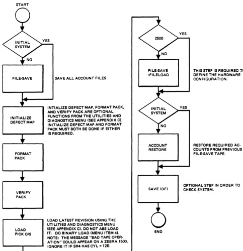
START
FILE-5AVE
INITIALIZE DEFECT MAP
FORMAT PACK
VERIFY PACK
LOAD PICK O/S
SAVE ALL ACCOUNT FILES
INTIALIZE DEFECT MAP, FORMAT PACK, AND VERIFY PACK ARE OPTIONAL FUNCTIONS FROM THE UTILITIES AND DIAGNOSTICS MENU (SEE APPENDIX C). INITIALIZE DEFECT MAP AND FORMAT . PACK MUST BOTH BE DONE IF EITHER
IS REQUIRED.
LOAD LATEST REVISION USING THE UTILITIES AND DIAGNOSTICS MENU (SEE APPENDIX C). DO NOT ABS LOAD IT. DO BINA.RY LOAD (MENU ITEM 4). NOTE: THE MESSAGE "BAD TAPE OPER-ATION" COULD APPEAR ON A ZEBRA 1500. IGNORE IT IF SR4 HAS CYL -12E.
FILE-5AVE :FILELOAD
ACCOUNT RESTORE
SAVE (OF)
END
Figure 2-1. Initial Load/Reload Operating System
THIS STEP IS REQUIRED TO DEFINE THE HARDWARE CONFIGURATION.
RESTORE REQUIRED AC-COUNTS FROM PREVIOUS FILE-5AVE TAPE.
[image:39.618.89.573.99.599.2]terminal control language
(Tel)
3
TCL is a language processor that provides the communication media between a user-operator.and the PICK operating system. All other processors, such as EDITOR, BASIC, and ACCESS, are invoked by TeL. In addition, any PICK verb in a command sentence is invoked from a keyboard, or from direct execution by a PROe, .which is a series of stored instructions.
TCL is automatically entered during LOGON and returned to whenever a
particular verb process (such as LIST, DUMP, COUNT), or a series of processes are complete. The display prompt for TCL is
">".
This prompt is displayed at the upper left of the display and indicates that the system awaits input from the keyboard.A TCL input statement will implement one of a set of verbs residing in the user's Master Dictionary (MO) (see Section 6). This verb will perform a set of steps specified at the keyboard, or will involve another processor to carry out specified steps. The latter is often the case where the "specified steps" are commonly used and required frequently. For example, the "RUN PROGRAMS ABC" causes the BASIC program ABC in the PROGRAMS file to be executed.
3.1 TCL VERB TYPES
The TCL verbs are of three types: TYPE-I verbs perform specific functions, but do not access file data. For example, TIME is a TYPE-I verb. TYPE-II verbs are those which access file data. For example, RUN, COPY, COMPILE are TYPE-II verbs. The TYPE-III verbs are for ACCESS, providing the user with immediate access, via keyboard, to his file data. USing the TYPE-III verbs, he has an unlimited flexibility for selecting the desired data, formatting and presenting it. These verbs are totally covered in the PICK Reference Manual, ACCESS
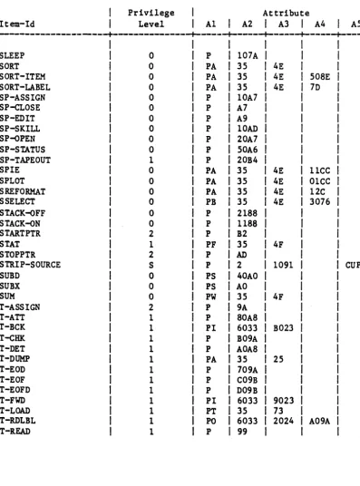
3.2 TCL VERB ATTRIBUTES
Table 3-1 identifies PICK verbs in alphabetical sequence and by type. The key attribute identifiers shown in this table (such as attribute 1 for OIVO is "PO") are defined as follows:
Attribute Number
o
1
2
3
4
Description
This is the item-id. which is the name of the verb.
Must contain a P optionally followed by another letter.
P identifies The letter processor. A defines
Q defines Y defines Z defines
the MD item as a verb definition item. following P is passed to the defined
Some of these are: an ACCESS verb. a PROC verb. a TCL-II verb. a TCL-I verb.
This attribute defines the processor entry point to which TCL passes control (i.e •• the mode-id in hex). An ACCESS verb will have an entry of:
35
A Type-II verb will have an entry of:
2
A Type-I verb will have an entry of:
x xxx
where xxxx is the entry point.
Secondary transfer point. Use depends on attributes 1 and 2.
5 TCL-II parameter string. These parameters govern treatment of the items retrieval by TCL-II verbs to be passed to the processor whose entry point is defined in attribute three. Parameter may be any of the following:
C Copy item to a work area.
F Pick up file parameters only (ignore item-list).
N Okay if item is not on file.
P Print item-id if item-list is
It*"
(all items) or if SELECT-ed item-list.S Ignore the select-list; item-list is mandatory.
U Items will be updated by processor.
Z Final entry required on EOI.
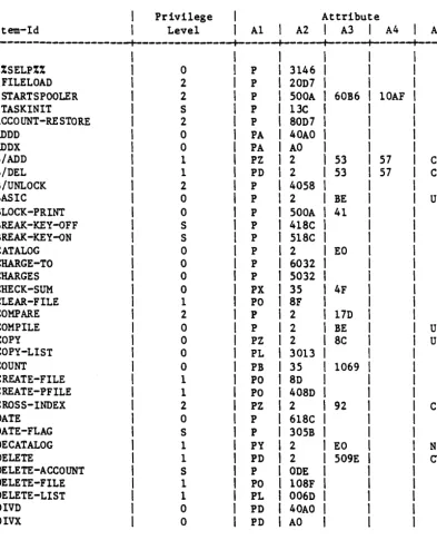
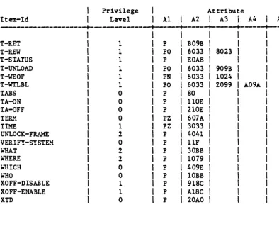
3.3 TCL VERB LIST
Table 3-1. PICK Verbs (Sheet 1 of 5)
Privilege Attribute
Item-Id Level A1
I
A2I
A3I
A4I
A5---+---+---+---+---+---+----%%SELP%% 0 P 3146
:FILELOAD 2 P 20D7
: START SPOOLER 2 P 500A 60B6 lOAF
:TASKINIT S P 13C
ACCOUNT-RESTORE 2 P 80D7
ADDD 0 PA 40AO
ADDX 0 PA AO
B/ADD 1 PZ 2 53 57 CS
B/DEL 1 PD 2 53 57 CS
B/UNLOCK 2 P 4058
BASIC 0 P 2 BE UP
BLOCK-PRINT 0 P 500A 41
BREAK -KEY -OFF S P 418C
BREAK -KEY-oN S P 518C
CATALOG 0 P 2 EO
CHARGE-TO 0 P 6032
CHARGES 0 P 5032
CHECK-SUM 0 PX 35 4F
CLEAR-FILE 1 PO 8F
COMPARE 2 P 2 17D
COMPILE 0 P 2 BE UP
COpy 0 PZ 2 8C UZ
COPY-LIST 0 PL 3013
I
COUNT 0 PB 35 1069
I
CREATE-FILE 1 PO 8D
t
CREATE-PFILE 1 PO 408D
I
CROSS-INDEX 2 PZ 2 92
I
CDATE 0 P 618C
I
DATE-FLAG S P 305B
I
DECATALOG 1 PY 2 EO
I
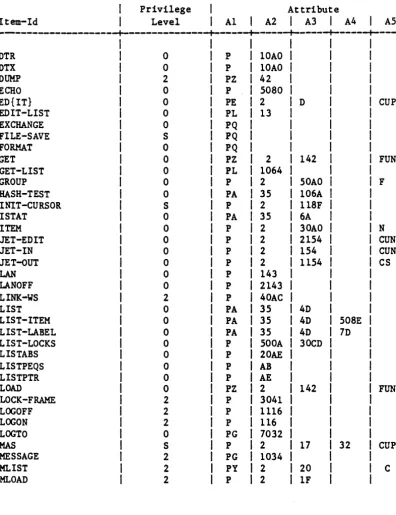
N [image:44.626.54.448.203.697.2]Table 3-1. PICK Verbs (Sheet 2 of 5)
Privilege Attribute
Item-Id Level A1
I
A2I
A3I
A4I
AS---+---+---+---+---+---+----DTR 0 P 10AO
DTX 0 P 10AO
DUMP 2 PZ 42
ECHO 0 P 5080
ED{IT} 0 PE 2 D CUPN
EDIT-LIST 0 PL 13
EXCHANGE 0 PQ
FILE-SAVE S PQ
FORMAT 0 PQ
GET 0 PZ 2 142 FUN
GET-LIST 0 PL 1064
GROUP 0 P 2 50AO F
HASH-TEST 0 PA 35 106A
INIT-CURSOR S P 2 118F
I STAT 0 PA 35 6A
ITEM 0 P 2 30AO N
JET-EDIT 0 P 2 2154 CUN
JET-IN 0 P 2 154 CUN
JET-oUT 0 P 2 1154 CS
LAN 0 P 143
LANOFF 0 P 2143
LINK-WS 2 P 40AC
LIST 0 PA 35 4D
LIST-ITEM 0 PA 35 4D 50SE
LIST-LABEL 0 PA 35 4D 7D
LIST-LOCKS 0 P 500A 30CD
LISTABS 0 P 20AE
LISTPEQS 0 P AB
LISTPTR 0 P AE
LOAD 0 PZ 2 142 FUN
LOCK-FRAME 2 P 3041
LOGOFF 2 P 1116
LOGON 2 P 116
LOGTO 0 PG 7032
MAS S P 2 17 32 CUP
MESSAGE 2 PG 1034
MLIST 2 PY 2 20 C
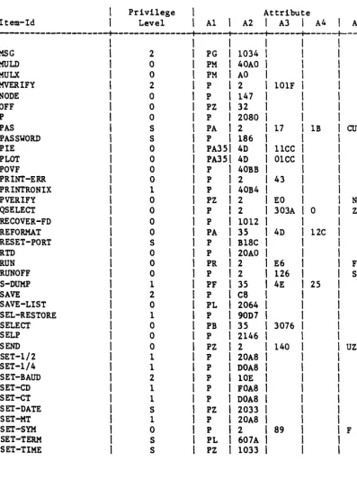
[image:45.618.85.482.168.684.2]Table 3-1. PICK Verbs (Sheet 3 of 5)
Privilege Attribute
Item-Id Level A1
I
A2I
A3I
A4I
AS---+---+---+---+---+---+-===
I
I
I
MSG
I
2 PGI
1034I
MOLD
I
0 PMI
40AOI
MULX
I
0 PMI
AOI
MVERIFY
I
2 PI
2 101FI
NODE
I
0 PI
147,
OFF
I
0 PZ,
32I
P
,
0 P,
2080,
PAS
,
S PAI
2 17 1BI
CUPPASSWORD
I
S PI
186,
PIE
,
0 PA3S' 4D 11CCI
PLOT
I
0 PA3S' 4D 01CCI
POVF
,
0 P,
40BB,
PRINT-ERR
,
0 PI
2 43,
PRINTRONIX
I
1 PI
40B4I
PVERIFY
I
0 PZI
2 EOI
NQSELECT
I
0 PI
2 303A 0I
ZRECOVER-FD
I
0 PI
1012I
REFORMAT
,
0 PAI
35 4D 12CI
RESET-PORT
,
S P,
B18CI
RTD
I
0 P,
20AOI
RUN
,
0 PR,
2 E6I
FRUNOFF
I
0 PI
2 126I
SS-DUMP
I
1 PF,
35 4E 25,
SAVE
,
2 P,
C8I
SAVE-LIST
I
0 PLI
2064I
SEL-RESTORE
I
1 PI
90D7I
SELECT
I
0 PBI
35 3076I
SELP
I
0 P,
2146I
SEND
I
0 PZI
2 140I
UZSET-1/2
I
1 PI
20A8,
SET-1/4
I
1 PI
DOA8I
SET-BAUD
I
2 PI
10EI
SET-CD
I
1 PI
FOA8I
SET-CT
,
1 PI
DOA8I
SET-DATE
I
S PZI
2033I
[image:46.626.51.449.144.687.2]Table 3-1. PICK Verbs (Sheet 4 of 5)
Privilege Attribute
Item-Id Level A1 I A2 I A3 I A4 I A5
---+---+---+---+---+---+----SLEEP 0 P 107A
SORT 0 PA 35 4E
SORT-ITEM 0 PA 35 4E 508E
SORT-LABEL 0 PA 35 4E 7D
SP-ASSIGN 0 P 10A7
SP-cLOSE 0 P A7
SP-EDIT 0 P A9
SP-SKILL 0 P lOAD
SP-oPEN 0 P 20A7
SP-STATUS 0 P 50A6
SP-TAPEOUT 1 P 20B4
SP!E 0 PA 35 4E 11CC
SPLOT 0 PA 35 4E 01CC
SREFORMAT 0 PA 35 4E 12C
SSELECT 0 PB 35 4E 3076
STACK-oFF 0 P 2188
STACK-oN 0 P 1188
STARTPTR 2 P B2
STAT 1 PF 35 4F
STOPPTR 2 P AD
STRIP-SOURCE S P 2 1091 CUP
SUBD 0 PS 40AO
SUBX 0 PS AO
SUM 0 PW 35 4F
T-ASSIGN 2 P 9A
T-ATT 1 P 80A8
T-BCK 1 PI 6033 B023
T-CHK 1 P B09A
T-DET 1 P AOA8
T-DUMP 1 PA 35 25
T-EOD 1 P 709A
T-EOF 1 P C09B
T-EOFD 1 P D09B
T-FWD 1 PI 6033 9023
T-LOAD 1 PT 35 73
T-RDLBL 1 PO 6033 2024 A09A
[image:47.620.88.485.165.701.2]Table 3-1. PICK Verbs (Sheet 5 of 5)
Privilege Attribute
Item-Id Level A1 A2
i
A3I
A4 I I AJ---+---+---+---+---+---+----T-RET 1 P B09B
T-REW 1 PO 6033 8023
T-STATUS 1 P EOA8
T-UNLOAD 1 PO 6033 909B
T-WEOF 1 PN 6033 1024
T-WTLBL 1 PO 6033 2099 A09A
TABS 0 P 80
TA-oN 0 P 110E
TA-QFF 0 P 210E
TERM 0 PZ 607A
TIME 1 PZ 3033
UNLOCK-FRAME 2 P 4041
VERIFY-SYSTEM 0 P 11F
WHAT 2 P 30BB
WHERE 2 P 1079
WHICH 0 P 409E
WHO 0 P 10BB
XOFF-DISABLE 1 P 918C
XOFF-ENABLE 1 P A18C
XTD 0 P 20AO
NOTES:
Privilege Level indicates the minimum system privileges needed to use a verb.
Levels are: 0, 1, 2, and S.
The lowest is O.
[image:48.623.48.443.155.478.2]3.4 VERB DEFINITION FOR MD
Examples of verb definition items using the attributes shown in Table 3-1:
1. Define the ACCESS verb LIST:
item 'LIST' in MD
001 PA 002 35
003 4D
2. Define the TeL-II verb COPY:
item 'COpY' in MD
001 PZ
002 2
003 8C
004
005 UZ
3. Define the TCL-I verb TIME:
item 'TIME' in MD
001 PZ
002 3033
Any number of synonyms for such verb definition items may be created (or