NAVIGATION SYSTEMS IN NOE FLIGHT SENSORS AND
THEIR INTEGRATION
N. Tamilselvam, D. Divya Priya,
B. Rajeswari and N. Siddika
Department of Aeronautical Engineering, Adhiyamaan College of Engineering Hosur, Tamilnadu, India E-Mail: [email protected]
ABSTRACT
This project presents the optimization method for Nap-of-the-Earth. The Nap of the Earth (NOE) mode is the most exciting, most dangerous, and is typically the slowest. It is used by military aircraft to avoid enemy detection and attack in a high-threat environment. NOE is used to minimize detection by the ground-based radar, targets and the control system. The Radar Altimeter or Terrain-Following Radar system, Terrain Awareness and Warning system is used to detect the obstacles during flying in NOE flights. Here, while the flight is at nap of the earth operation, the speed and the altitude must be slow as already determined. The terrain following radar maintains the altitude from the ground level. So we analyze the problem to increase the performance of the aircraft by ranging the terrain by some modes of the Terrain Avoidance and Warning System which is given by ICAO, UKCA, EASA, and FAA. Further to this, different TAWS modes of operation, explanation of mode selection and advancement in TAWS are explained in detail. In this paper, MATLAB programming is done for some modes of TAWS operation and the simulation of flight path for the excessive terrain. Closure rate from mode 2 operation of flight is also done.
Keywords: nap-of-the-earth, radar system, optimization method, high-threat environment, terrain avoidance and warning system.
INTRODUCTION
Nap-of-the-earth (NOE) is a type of very low-altitude flight course used by military aircraft to avoid enemy detection and attack in a high-threat environment. This mode is the slowest and more exciting. When flying at the nap of the earth, the pilot flies at varying airspeeds and altitudes and stays as close to the earth’s surface as possible. During NOE flight, geographical features are also used. This keeps below enemy radar coverage. NOE is used to minimize detection by hostile aircraft, ground-based radar, or attack targets. Doppler radar has the potential to determine NOE flight, but the aircraft that comes towards has to be within radar range in the first place, and low flight minimizes this possibility due to the effect of terrain masking.
The lowest NOE flying is by helicopters because they have lower speeds and more maneuverability than fixed-wing aircraft, mainly in the fast-jets. Only Helicopters can fly at treetop levels or even below the height of surrounding trees where there are clear areas (such as in river gullies), flying under wires (such as electricity cables) over them. Attack helicopters can hide behind trees or buildings, popping up just enough to use their (rotor mast-mounted) radar or other sensors and then minimally exposing themselves to launch weapons. Then the escape can be made by further NOE flying.
The Figure-1 represents the nap of the earth operation. In this the high level path and the low level path of the flight is represented. The high level path is identified by the radar system from the base, while the low level flight path used fly under the radar which is called as the NOE flying technique. They have their own flight path which avoids the collision with terrain.
Figure-1. Nap of the earth flight.
Obstacle Detection and Analysis
There are two types of obstacle detection in NOE flights 1.Obstacle Detection Using Passive Sensors and 2.Obstacle Detection Using Active Sensors.
Obstacle Detection Using Passive Sensors
Passive sensors are patterned after radio astronomy instruments, which detect emissions having very low power. They are particularly sensitive to accumulated radiation from a multitude of emitters on the ground, both from within the frequency band in which measurements are being made, and from out-of-band. Space borne passive sensors provide the ability to obtain all-weather, day and night, global observations of the Earth and its atmosphere. These space borne passive sensors operate in frequency bands allocated to the Earth Exploration-Satellite Service or to the Space Research Service.
Obstacle Detection Using Active Sensors
An active sensor is a radar instrument used for measuring signals transmitted by the sensor that were reflected, refracted or scattered by the Earth's surface or its atmosphere. Space borne active sensors have a variety of applications related to meteorology and observation of the Earth's surface and atmosphere. For example, precipitation radars measure the radar echo from rainfall to determine the rainfall rate over the Earth's surface; and cloud profile radars measure the radar echo return from clouds to provide a three dimensional profile of cloud reflectivity over the Earth's surface. Space borne active sensors operate in the Earth Exploration-Satellite Service or in the Space Research Service. Active sensor frequency allocations are often shared with other radar, as such systems are normally compatible with the operation of the sensors.
Radar Altimeter (RA)
The radio altimeter is often erroneously described as a "radar altimeter". Hence it does not use radar principles beyond the fact that it responds to reflected signals. Radar emits high power pulses which are reflected back by water and other reflective surfaces. The radio altimeter uses the time delay between the transmitted and received signals to determine the distance to the precipitation or ground targets. Radar is used to display targets to approximately 300 miles. (Give or take depending on the model)
A radio altimeter broadcasts an FM modulated continuous wave 4GHz signal. Their frequency is modulated on a "ramp" so that it changes in a linear fashion. Frequency between the transmitted signal and the reflected received signal is continuously monitored and processed to display altitude above the terrain. It is mainly designed to display the distances from 0 to 2500 feet (give or take depending on the model). It is not active when the aircraft is above 2500 feet. (again, give or take depending on the model). The figure 5 shows the equipment of radar altimeter with some deflection. It deflects with corresponding to the change in the fight altitude. This prevent the flight from disaster by giving the exact altitude with the ground level.
A typical radio altimeter system on an airliner uses two antennas. Were one antenna transmits the signal
while the other receives. These are basically situated as near the point of rotation as possible. Usually under the fuselage, between the wings. The antennas should never be located at the nose or tail because angle of attack could then contribute serious errors. For instance, if they were in the nose, flaring could cause the auto land system to think that the aircraft is ascending. The antenna installation is very critical. The positioning of the antennas and even the length of the antenna cables must be considered. Radio altimeter technology is also employed in military applications, most commonly among helicopters and other low-flying craft to avoid radar detection. It also functions as a component in terrain-following radar, allowing a craft to fly at high speeds over varied topography.
Figure-2. Radar altimeter.
TERRAIN FOLLOWING RADAR (TFR)
the ground hitting probability and the probability of kill by the weapons which varies in the order with risk and terrain clearance plot.
Scanning of Terrain Following Radar
A TFR system will scan the airspace in front of the aircraft with a vertical scan forming a wedge of data in both the altitude and azimuth directions. An antenna scan pattern to produce this wedge is shown in Figure. In this type of scan, the horizon will be near the middle of the vertical scans, which will produce the wedge in the left side, right side, then above and below the aircraft. All ground returns gathered by this scan are collected and measured. The scan pattern is, this shows when the flight that scans the terrain from the flight path for the airspace in front of the aircraft .The scan pattern which transmitted from the flight is deflected and returned and that collected data is measured then.
Figure-3. Terrain following radar vs risk.
Figure-4. Terrain following radar scan.
Algorithm of Terrain Following Radar
There have been several approaches to the terrain-following algorithms. The typical algorithm of terrain following radar is shown in the Figure-5 (a, b,c, d) which represents the following alogorithms. They are: Template Algorithm, Angle Algorithm, Advanced Low Altitude Algorithm, Path Following Algorithm.
Template Algorithm
This is the approach patented by Bert Bechtel in 1959. This method is shown in the first diagram in Figure 5 (a). This algorithm involves creation of a two-part virtual line in the space in front of the aircraft. The lower section is the desired set clearance, and the slope of the upper section is based upon the climb capacity of the aircraft. As the radar scans the space in front of the aircraft, it monitors all terrain that can be seen. As returns are collected, the range and angle to the terrain is collected and stored. If the terrain or other object crosses the template line, a pull up command is generated proportional to the range in front of the aircraft. As the terrain clears the template line, a push down command is generated to return to the original set clearance desired by the pilot. This system was implemented using analog processing prior to the advent of digital circuitry.
Angle Algorithm
Further work on the template algorithm produced the angle model, shown in the second drawing in Figure 5 (b). This method uses sums of angles, which were suitable to the analog systems of the time, which predates digital computing. In this method, the lower line in the figure is the desired set clearance of the aircraft. The β in the figure is the antenna scan angle and θ is the pitch angle of the aircraft.
When these are combined, you get an angle to the object. Ho is the desired set clearance and R is the range to the point of interest. For small angles, the angle can be approximated by Ho/R. The last factor is Γ, which is a margin factor to allow for the push-over point at the peak of the climb to not drop below the set clearance. This factor is tuned to the response of the aircraft. The algorithm was further refined to utilities parts of the template approach and was tuned to only respond to objects in a relatively near range and ignore objects at large ranges.
Advanced Low Altitude Algorithm
Path Following Algorithm
The last method is the path-following algorithm is shown in the Figure-5 (d), which requires a significant increase in computation power over the prior methods. In this method, the flight path is considered to be the terrain with the offset being the set clearance. This path is followed by making a tracking algorithm and correcting for the offsets as the flight passes over the obstacle. To accomplish this, a large number of terrain points are collected and the computation is constantly updated.
Terrain Awareness and Warning System (TAWS) and its Working
Terrain Awareness and Warning System is airborne safety equipment designed to reliably and automatically providing the flight crew with warning of collision with terrain. The most commonly using TAWS is Ground Proximity Warning System (GPWS). Hence GPWS is developed only by means of the TAWS.
Figure-5 (a, b, c, and d). Terrain following radar computation approaches.
TAWS use GPS positioning and a database of terrain and obstructions to provide true predictability of the upcoming terrain and obstacles. The warnings it provides pilots are both aural and visual, instructing the pilot to take specific action. Because TAWS relies on GPS and a database of terrain/obstacle information, predictability is based upon aircraft location and projected location. The system is time based and therefore compensates for the performance of the aircraft and its speed. The GPWS was based only upon radio altimeter inputs, TAWS takes account of actual aircraft position in relation to a terrain map contained in the equipment. This actual position is determined by either built-in GPS. The Terrain Awareness and Warning System works by using the digital elevation data and the instrumental values of the aircraft to aware the future position of the aircraft which will intersects with the ground. So the crew is provided with earlier aural warning and visual warning of the terrain and the upcoming looking capability. The Figure-6 shows the typical Terrain Awareness and Warning System (TAWS) (right side). Here on the other side (left side) the
reference altitude indicates the different colors for the corresponding altitude rate from the mean sea level which is observed by the aircraft using TAWS. There are mainly three classes in the Terrain Awareness and Warning System. They are TAWS class A, TAWS class B and TAWS class c.
EASA (European Aviation Safety Agency)
By the EU-OPS 1.665 - GPWS and TAWS; Applicability. This ETSO gives the requirements which Terrain awareness and Warning System (TAWS) equipment that is manufactured on or after the date of this ETSO, must meet in order to be identified with the applicable ETSO marking.
Figure-6. Terrain awareness and warning system.
Minimum Performance Standards
Phase of Flight : Definitions For appendix 4, the terms “takeoff,”“cruise,” and “landing” are used instead of “departure,”“reroute,” and “approach” because they are more suitable to the
GA environment: Takeoff - positive required obstacle clearance (ROC), inside traffic area, distance to nearest runway threshold is increasing, and airplane is below 1, 000 feet.
Cruise - anytime the airplane is outside the airport traffic control area.
Landing - inside traffic area and distance to nearest runway threshold is decreasing, and airplane is below 1,000 feet.
Altitude Accuracy
MSL-G, or other obvious acronym that relates to the pilot that altitude is GPS derived MSL altitude.
Modes of Operation
The various sets of hazardous conditions that the GPWS monitors and provides alerts for are commonly referred to as Modes. These are described in detail in the following paragraphs. Hazard awareness is provided by TAWS aural alerts or warnings and illumination of alert and warning lights in response to different situations. The Table-1 shown below illustrates a typical TAWS system mode of the operation of flight respectively.
Response to TAWS Activation
TAWS is a safety net in which a (Hard) Warning indicates that the aircraft is in a dangerous situation and immediate action is required and an alert (or soft warning)
indicates an abnormal status in relation to terrain which invites prompt review and a possible change of flight path or aircraft configuration. Appropriate TAWS response procedures for flight crew are determined after careful study of aircraft type performance capability. They must be clearly defined by operators and, in the case of a Warning, should be followed without hesitation as soon as a triggered. Operators normally define different response procedures based upon memory drills for a Warning (sometimes called a Hard Warning) and an immediate review in the case of an Alert (sometimes called a Soft Warning)
The EU-OPS Regulatory requirements related to TAWS are: When undue proximity to the ground is detected ... by a ground proximity warning system, the commander or the pilot to who conduct of the
Table-1. Typical TAWS system mode of the operation of flight.
Mode Condition Aural alert Aural warning
1 Excessive descent rate “SINKRATE” “PULL UP”
2 Excessive terrain closure rate “TERRAIN TERRAIN” “PULL UP”
3 Excessive attitude loss after
take-off or go around “DON’T SINK” (NO WARNING)
4a Unsafe terrain clearance while
gear not locked down “TOO LOW GEAR”
“TOO LOW TERRAIN”
4b Unsafe terrain clearance while
landing flap not selected “TOO LOW FLAP”
“TOO LOW TERRAIN”
4c Terrain rising faster than aircraft after take off
“TOO LOW
TERRAIN” (NO WARNING)
5 Excessive descent below ILS
Glideslope “GLIDESLOPE” “GLIDESLOPE”(1)
6a Advisory Callout of radio Height (for example) “ONE
THOUSAND” (NO WARNING) 6b Advisory Callout of Bank Angle “BANK ANGLE” (NO WARNING)
7 Wind shear protection “WINDSHEAR” (NO WARNING)
NOT MODE Terrain Proximity “CAUTION “TERRAIN
TERRAIN
NUMBERED TERRAIN” PULL UP”
Flight has been delegated shall ensure that corrective action is initiated immediately to establish safe flight conditions. (EU-OPS 1.395)
PROBLEM DESCRIPTION
In this chapter MATLAB program and its description were explained for the TAWS mode. Here for Mode 2 the “Excessive terrain closure rate” determination is programed and the result is obtained.
This program is created by using altitude measuring formula. Taking random pressure values for the various altitude conditions are used.
� = [����] ���0 − lnP
Equation.1
Where Z- Height from the ground, RT- Gas constant temperature,
g- Gravity, - Random pressure value, – Sea level pressure respectively.
TERRAIN” “PULL UP” message and when it comes to normal steady flight it shows “NO WARNING” message. This performance is represented by the following program.
MATLAB Programming
1. Program for Mode 2 ‘excessive terrain closure rate
The altitude measuring formula is used to solve this mode of operation as stated in problem description.
� = [����] ���0 − lnP
Equation.2
Here, at the mode 2 operations set the ‘z’ value more than 2500 ft, then it will show “NO WARNING” message. When it drops to 2500ft and below it will show TERRAIN TERRAIN message and if reduced to 1500 ft, PULL UP message will shown.
Input Data Clear all; clc;
%% Definition of input pressure
P = 1e3.*[75.232 70 60 50 65 75 80 76 60 65 70 75 80 84 89 80 76 70 65 60 55]'; %% Initialization of other required parameters
Rsp = 287; %( J/(kg /(kg K)) specific gas constant for air T = 298; %( kelvin) assuming constant temperature throughout altitude Pnot = 101.325e3; %(Pa) sea-level pressure
��� = 2 ; % / �
T = 298; %( kelvin) assuming constant temperature throughout
altit
ude Pnot =101.325e3; %(Pa) sea-level pressure
% % Calculation of height and display of message for i=1 size (P);
Display (‘NO WARNING’) Elseif (z(i)>=2500)
Disp(‘TERRAIN TERRAIN’) Else
Disp(‘PULLUP’) End
End %%Note
%z = 2500 corresponds to P = 75.232 kPa %z = 1500 corresponds to P = 84.748 kPa %z = 0000 corresponds to P = 101.325 kPa
Result of the Program Output Data
NO WARNING NO WARNING
NO WARNING NO WARNING NO WARNING NO WARNING TERRAIN TERRAIN NO WARNING NO WARNING NO WARNING NO WARNING NO WARNING TERRAIN TERRAIN TERRAIN TERRAIN PULL UP
TERRAIN TERRAIN NO WARNING NO WARNING NO WARNING NO WARNING NO WARNING
Program for the Simulation of Excessive Closure Rate In this Simulation of Excessive Closure Rate we are going to simulate the aircraft moving on its path without collision with the terrain using the terrain awareness and warning system (mode 2) as per the regulation. The Mode 2 warns flight crew of excessive closure rates with the rapidly rising terrain. If terrain rises significantly within 2000 ft of the aircraft, the terrain closure rate is measured. Up to this stage the “NO WARNING” message is displayed and when the aircraft reaches the maximum closure value at the higher threat condition the “TERRAIN TERRAIN PULL UP” message is displayed. And when the aircraft passes the terrain it came to normal low level fight and then “NO WARNING” message is shown.
Input Data
%#control animation Speed DELAY =0.1; Num = 1000; Num1 =500 %#create Data
X=linspace(pi,pi,num); C=linspace(-4pi,num1) E=linspace(pi,6,num1) Y=(sin(x+1.5)) S=(sin(x+1.5))+1.5 D=zeros(1,num,1) For k=1;num 1 D(1,k)=0.5 End
F(1,1)=0,5 End
%#plot graph
Plot(x,y,x,s,c,d,e,f),xlabel(‘x’), ylabel(‘y’),title(‘Flight Path’),grid on %#create moving point+cords text
hLine=line(XData’,x(1),’YData’,s(1),’Colour’,’r’ ‘Marker’,’^’,’MarkerSize’,15,’lineWidth’2); hTxt1=textc(1),d(1),sprint(‘(%.3f,%3f)’,c(1),d(1)), ‘colour’,’r’,’Fontsize’, 10
‘Horizontal Alignment’,’left’,’VerticalAlignment’,’Top’); For j=1:length(c)
Disp(‘Warning!! TERRAIN TERRAIN PULL UP!!’) Set(hText,’Position’,c{j}d[j}
‘String’,sprint(‘(%.3,%.3f)’,[c(j)d]))drawnow J=rem(j+1,num1)+1;
If-ishandle(hline),end End
Fori=1:length(x) Set(hline,’XData’,x(i), N=rem(n+1,num1)+1; Display(‘NO WARNING’) ELSEIF(Z(I)>=2500) Disp(“TERRAIN TERRAIN’) Else
Disp(‘PULLUP’) END
END
Result of the Program OUTPUT DATA NO WARNING NO WARNING NO WARNING NO WARNING NO WARNING NO WARNING
NO WARNING NO WARNING NO WARNING
WARNING!! TERRAIN TERRAIN PULL UP!! WARNING!! TERRAIN TERRAIN PULL UP!! WARNING!! TERRAIN TERRAIN PULL UP!! WARNING!! TERRAIN TERRAIN PULL UP!! WARNING!! TERRAIN TERRAIN PULL UP!! WARNING!! TERRAIN TERRAIN PULL UP!! WARNING!! TERRAIN TERRAIN PULL UP!! WARNING!! TERRAIN TERRAIN PULL UP!! WARNING!! TERRAIN TERRAIN PULL UP!! NO WARNING
NO WARNING NO WARNING NO WARNING NO WARNING NO WARNING NO WARNING NO WARNING NO WARNING
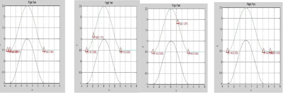
This is the result obtained from the MATLAB program for the simulation of terrain awareness and warning system (Mode 2). And the simulated representation of this output is given in the following Figure (a, b, c, d).
Graphical Representation (Mode 2)
In this, the movement of the flight along the defined path is determined. Mode 2 warns flight crew at excessive closure rates with the rapidly rising terrain using exact Airspeed, Rate of Descent and Radar Altitude. The TAWS compares the terrain below the aircraft to the flight path. If the terrain rises significantly within 2000 ft of the aircraft, the maximum closure rate is measured.
[image:7.595.70.531.580.732.2]
When the closure rate shows danger to the aircraft, the TAWS warning lamp will illuminate and the voice alert “TERRAIN TERRAIN” will be heard. If the closure rate is continuous or worseness the voice call out will change to a continuous “PULL UP” warning until terrain is no longer a threat. “TERRAIN TERRAIN PULL UP” command is the alert that we have gained in our program. By the above said parameters, the simulation is done finaly and they are shown as below Figure-7 (a, b, c, d).
CONCLUSIONS
This project presented the optimization method for Nap-of-the-Earth flight operation using the sensors. In the nap of the earth operation, if we took in to the deep look, the use of Terrain awareness and warning system has drastically decreased the collision with ground or the obstacles which are occurred while on controlled flight. However with the advanced technological improvements and modern equipment, the accidents of collision are still happening.
The establishment of new systems and improving the existing ones may lead to prevent the accidents while flying at nap of the earth operation or at the low level flying. Hence the proper training to the pilot is mandatory to fly at the low altitude level with using the advanced equipment. Here in this project the Terrain awareness and warning system (TAWS) is taken for the safe flight operation. Further to this, different TAWS modes of operation and the explanation of mode selection in TAWS are explained in detail. The MATLAB programming was done for one mode of TAWS operation and the simulation of flight path for the excessive terrain closure rate from the mode 2 operation of flight is determined and the outputs are gained for the Nap of the Earth flights.
REFERENCES
[1] Helicopters at War- Blitz Editions, Bookmart Limited, 1996,ISBN 1-85605-345-8.
[2] Proceedings of the IEEE 1979 National Aerospace and Electronics Conference NAECON 1979. IEEE. Part III, 1979, pp.1089-96. New York, NY, USA. (1979).
[3] System for Obstacle Detection During Rotorcraft Low Altitude Flight – by B. Bhanu, S. Das, B. Roberts, D. Duncan -DOI:10.1109/7.532250A-(Aug, 1996).
[4] Radar/ Radio 2013flight Instruments and Radio Navigational Aids- Radar/ Radio Altimeter by Bilal Ahmad (Nov, 2013).
[5] CS-ETSO/Amendment 2 - Change Information - EASA -(Oct 24, 2003).
[6] Federal Aviation Administration, 14 CFR Parts 91, 121, 135- (Dec 17, 2002).