An Iterative Maximum Likelihood Synchronization
Method for OFDM System
Chi-Min Li, Wei-Tse Sun
Department of Communications, Navigation and Control Engineering, National Taiwan Ocean University, Keelung, Chinese Taipei Email: [email protected]
Received 2013
ABSTRACT
OFDM system divides a wideband transmission bandwidth into several overlapped narrowband subcarriers to avoid the serious frequency selective fading problem. However, if Timing Offset (TO) and Carrier Frequency Offset (CFO) exist between the Transmitter (Tx) and Receiver (Rx), OFDM system will suffer the Inter-Symbol Interference (ISI) and In-ter-Carrier Interference (ICI) that degrade the system performance dramatically. In this paper, we propose an iterative maximum likelihood method for synchronization. We also adopt the overlap concept to reduce the plateau problem. Simulation results show that the proposed method can predict the time delay and frequency offset correctly even under the multipath fading scenarios.
Keywords: Synchronization; Maximum Likelihood; OFDM
1. Introduction
Orthogonal Frequency Division Multiplexing (OFDM) has been widely adopted in the current wireless commu-nication systems, such as IEEE 802.11 a/g, and Long Term Evolution (LTE). To correctly accomplish symbol detection, an OFDM system has to establish the time and frequency synchronization [1]-[7] firstly to avoid the Bit Error Rate (BER) degradation. Poor synchronization will destroy the orthogonal property of the received signal and system will suffer the Inter-Symbol Interference (ISI) and Inter-Carrier Interference (ICI). Therefore, synchro-nization is a very important issue for the transmission, especially for the OFDM system.
In [3], authors proposed a Maximum Likelihood (ML) method via adopting the correlation properties of the Cyclic Prefix (CP) with the copied portion of an OFDM symbol to achieve the time and frequency synchroniza-tion. Its performance depends notably on the length of the inserted CP. The longer of the length of CP, the better of the synchronization can be obtained. Based on this behavior, if we use a preamble with two repetitions to conduct the synchronization, the ML method should perform well. However, a serious plateau problem arises that causes the Receiver (Rx) can not predict the arrival time precisely. This problem comes from the inherent correlation properties of the preamble with two or multi-ple repetitions. Many methods have been proposed to reduce the plateau problem [2,4].
In this paper, we propose an iterative ML synchroniza-tion method that adopts the overlap concept to reduce the
plateau problem. This paper is organized as follows. In Section II, the conventional ML synchronization method and the proposed iterative method will be described in detail. Simulation results of these methods are compared in Section III. Finally, some conclusions for this paper are given in Section IV.
2. Method Descriptions
In OFDM system, Transmitter (Tx) can insert a CP at the Guard Interval (GI) of the OFDM signal to avoid the ISI. Assume the received signal can be expressed as
2 /
( ) ( ) j n N ( )
r n x n e w n (1)
where is the time delay, is the normalized
fre-quency offset and is the Additive White Gaussian
Noise (AWGN).
( ) w n
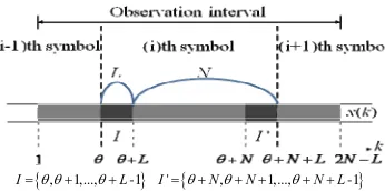
Consider an observation interval with 2N+L samples
(Figure 1), the interval contains a complete OFDM
sym-bol of N+L samples, where N is the number of subcarrier and L is the length of the CP.
, 1,..., -1 ' , 1,..., -1
[image:1.595.338.511.633.719.2]I L I N N N L
Define intervals I and I' as in Figure 1, the re-ceived signal has the following correlation properties [3]:
2 2 2
* 2 / 2 / *
* 2 / *
2 [ ( ) *( )]
( ) ( ) ( ) ( )
( ) ( ) ( ) ( )
, 0
, ,
0 , else
j m N j k N
j k N
x w j x
E r k r k m
E x k x k m e E x k e w k m E x k m e w k E w k w k m
m
e m N k I
(2)
[image:2.595.321.521.117.601.2] [image:2.595.62.289.425.590.2]where 2 2
[ ( ) ]
x E x k
is the energy of the transmitted
signal and 2 2
[ ( ) ]
w E w k
denotes the energy of the
AWGN.
Let the Log-Likelihood Function ( , ) be defined
as
* * 1 2 2 ( , )( ) ( ) cos 2 ( ) ( )
( ) ( )
2
L k
r k r k N r k r k N
r k r k N
(3)where
1 SNR SNR
is a constant related to the Sig-
nal-to-Noise Ratio (SNR) and denotes the phase.
The ML method estimates the time delay and frequency offset as Equation(5) and Equation(6) respectively.
( , ) ML 1 2 2 * max ( , )ˆ max ( , ( ))
( ) ( ) ( ) ( )
2 L
k
r k r k N r k r k N
(4)
ML 1 2 2 * ˆarg max ( ) ( ) ( ) ( )
2 L
k
r k r k N r k r k N
(5) ML ML ˆ 1 * ML ˆ 1 ˆ ( ) ( ) 2 L kr k r k N
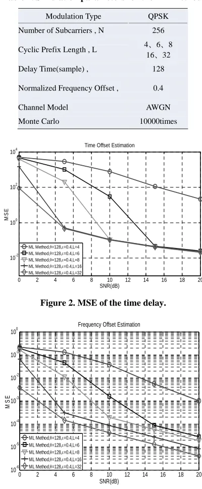
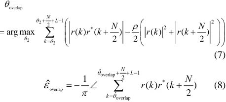
(6)In the ML merthod, the performance of the estimated time delay and frequency offset depend heavily on the length of the inserted CP. Table 1 lists the parameters for
the ML method in [3] under different lengths of CP.
Fig-ures 2 and 3 are the corresponding time and frequency
simulation results. According to the results, we can note that if we increase the length of the CP, the Mean Square Errors (MSE) for both the time and frequency offsets can be improved.
Based on above observation, if we use a preamble with two repetitions to conduct the synchronization, the ML method should perform well. A simple extension for the
ML method can be depicted in Figure 4.
Table 1. Simulation parameters for the ML method.
Modulation Type QPSK
Number of Subcarriers , N 256
Cyclic Prefix Length , L 4、6、8 16、32
Delay Time(sample) , 128
Normalized Frequency Offset , 0.4
Channel Model AWGN
Monte Carlo 10000times
0 2 4 6 8 10 12 14 16 18 20
10-2 100 102 104
Time Offset Estimation
SNR(dB)
MS
E
ML Method,=128,=0.4,L=4
ML Method,=128,=0.4,L=6
ML Method,=128,=0.4,L=8
ML Method,=128,=0.4,L=16
ML Method,=128,=0.4,L=32
Figure 2. MSE of the time delay.
0 2 4 6 8 10 12 14 16 18 20
10-6 10-5 10-4 10-3 10-2 10-1 100
Frequency Offset Estimation
SNR(dB)
MS
E
ML Method,=128,=0.4,L=4
ML Method,=128,=0.4,L=6
ML Method,=128,=0.4,L=8
ML Method,=128,=0.4,L=16
ML Method,=128,=0.4,L=32
Figure 3. MSE of the frequency offset.
'
, 1,..., 1 , , 1,..., 1
2 2 2
N N N
I I N
In Figure 4, we construct a preamble with two repeti-tions to conduct the ML estimation. The ML method calculates the correlation between the defined intervals I and I’. However, a serious plateau problem will arise. This problem comes from the inherent correlation prop-erties of the preamble with two or multiple repetitions. The plateau problem can be easily solved if we calculate
the cross-correlation in an overlap manner. Figure 5 is
an example that the intervals I and I’ are overlapped. In this case, the length of the overlap region is exactly to L. In the simulation part, we will demonstrate that with the help of the overlap region, the plateau problem can be efficiently reduced. The corresponding time delay and frequency offset estimations can be formulated as in Equation(7) and Equation(8).
overlap 2 2 2 1 2 2 2 * ˆ
arg max ( ) ( ) ( ) ( )
2 2 2
N L
k
N N
r k r k r k r k
(7) overlap overlap overlap ˆ 1 2 * ˆ 1 ( ) ( ) 2ˆ
N L k N r k r k
(8)The main difference between the Equations 5-6 with Equations 7-8 is the range for the cross-correlation cal-culation. The overlap concept can ease the plateau prob-lem of synchronization if a preamble contains multiple repetitions. Besides, the performance of the synchroniza-tion can be further improved if we adopt the iterasynchroniza-tion operation for the preamble. For example, if the Part-A of
the preamble in Figure 5 can be further constructed with
two repetitions as illustrated in Figure 6. The preamble
wilt multiple repetitions can be easily generated if we adopt the Constant Pilot Padding Method (CPPM) [9] proposed previously. Thereafter, we can conduct the fol-lowing iterative steps to increase the synchronization precision for both the time and frequency.
Step.1 Calculate the ML estimation for the intervals
(I and I') with N/2 separation in Figrue 7. In this
case, the intervals I and I' contain the overlap region with length equals to L.
L
'
2 2, 2 1,..., 2 1 , 2 2 , 2 1,..., 2 1
2 2 2
N N N
I L I
L N
[image:3.595.318.528.264.369.2]
Figure 5. Overlap cross-correlation calculation.
Figure 6. Preamble for iterative operations.
I
I’
CP B B B B
N/4
N/4 N/4 N/4
N/2+L
N/2+L
Figure 7. ML calculation for interval I and I’.
I’
CP B B B B
N/4
N/4 N/4 N/4
3N/2
3N/2
L
[image:3.595.59.288.273.377.2]I
Figure 8. ML calculation for interval I and I’
Step 2 Calculate the ML estimation for the intervals
(I and I') with N/4 separation in Figure 8. In this
case, the intervals I and I' contain the overlap region with length equals to N/2.
Step 3 Calculate the estimated time and frequency off-sets via the Equations 9-10. We can have more precise synchronization estimation which will be shown at the simulations in Section III.
1 2 1 Iterative 3 1 4 2 3 1 1 2 4 1 2
ˆ arg max{ ( )
( ) ( ) ( ) 2 N L k N L k L N N L L
k k L
θ k k k k
(9) Iterrative Iterrative ˆ 1 2 Iterative 1 ˆ 1ˆ ( )
N L k k
(10)where * 1 * 2 ( ) ( ) ( ) 2 ( ) ( ) ( ) 4 N k r k r k
N k r k r k
[image:3.595.63.284.614.719.2]2 2
1
2 2
2
( ) ( ) ( )
2
( ) ( ) ( )
4 N k r k r k
N k r k r k
(11)
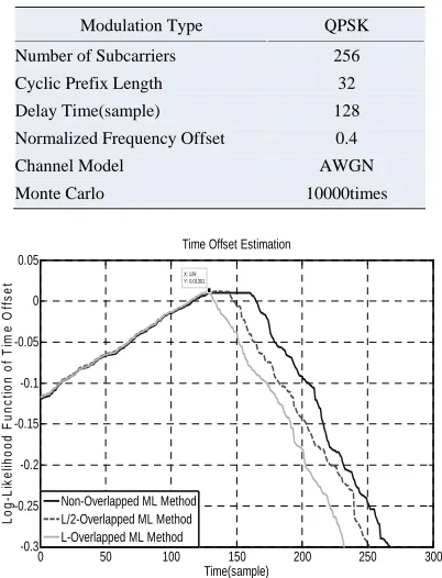
[image:4.595.333.515.87.237.2] [image:4.595.330.517.237.409.2]3. Computer Simulations
Table 2 lists the parameters to evaluate the proposed
over-lap concept. The delay time offset is 128 in this
simula-tion. Figrue 9 is the Log-Likelihood function calculation
if the two-repetition preamble conducts only non- over-lapped cross correlation calculation, L/2-overover-lapped cal-culation and the L-overlapped cross correlation calcula-tion respectively. Results show that if the length of over-lap equals to or greater than the length of CP, it can avoid
the plateau problem efficiently. Figures 10 and 11 are
[image:4.595.72.273.455.718.2]the corresponding time and frequency offsets estimation for different SNR scenarios. With the help of the over-lapped cross-correlation calculation, the proposed con-cept can predict the offsets correctly.
Table 3 lists the parameters to evaluate the proposed
iterative method under the multipath fading channel. Path attenuations are according to the Vehicular-A [8] channel
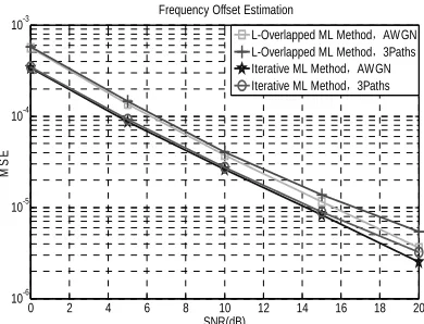
model. Figures 12 and 13 are the estimated time and
frequency offsets. Results show with the proposed itera-tive method, the synchronization precision can be further improved for both the AWGN and multipath fading chan-nels.
Table 2. Simulation parameters.
Modulation Type QPSK
Number of Subcarriers 256
Cyclic Prefix Length 32
Delay Time(sample) 128
Normalized Frequency Offset 0.4
Channel Model AWGN
Monte Carlo 10000times
0 50 100 150 200 250 300
-0.3 -0.25 -0.2 -0.15 -0.1 -0.05 0 0.05
Time Offset Estimation
Time(sample)
Lo
g-L
ik
el
iho
od
F
u
nc
ti
o
n o
f T
im
e
O
ff
s
et
X: 129 Y: 0.01301
Non-Overlapped ML Method L/2-Overlapped ML Method L-Overlapped ML Method
Figure 9. Log-Likelihood function calculation.
0 2 4 6 8 10 12 14 16 18 20
10-3 10-2 10-1 100 101 102 103
Time Offset Estimation
SNR(dB)
MS
E
Non-Overlapped ML Method L/2-Overlapped ML Method L-Overlapped ML Method
Figure 10. MSE of the timing offset estimation.
0 2 4 6 8 10 12 14 16 18 20
10-6 10-5 10-4 10-3 10-2 10-1 100
Frequency Offset Estimation
SNR(dB)
MS
E
Non-Overlapped ML Method L/2-Overlapped ML Method L-Overlapped ML Method
[image:4.595.308.538.457.719.2]Figure 11. MSE of the frequency offset estimation.
Table 3. Simulation parameters.
Modulation Type QPSK
Number of Subcarriers 256
Cyclic Prefix Length 32
Delay Time(sample) 128 132 136
Path Gain(dB) 0 -1 -9
Normalized Frequency Offset 0.4
Channel Model AWGN 3Paths Rayleigh Fading Channel
Monte Carlo 10000times
0 2 4 6 8 10 12 14 16 18 20
10-4 10-3 10-2 10-1 100 101 102
Time Offset Estimation
SNR(dB)
MS
E
L-Overlapped ML Method,AWGN
L-Overlapped ML Method,3Paths
Iterative ML Method,AWGN
Iterative ML Method,3Paths
[2] Z. S. Pang and X. M. Li, “A Novel Synchronization Al-gorithm for OFDM System Based on Training Sequence Added Scramble Code,” IEEE Communications Tech-nology and Applications (ICCTA), 2009
0 2 4 6 8 10 12 14 16 18 20
10-6 10-5 10-4 10-3
Frequency Offset Estimation
SNR(dB)
MS
E
L-Overlapped ML Method,AWGN
L-Overlapped ML Method,3Paths Iterative ML Method,AWGN Iterative ML Method,3Paths
[3] J. J. van de Beek, M. Sandell and P. O. Borjesson, “ML Estimation of Time and Frequency Offset in OFDM Sys-tems,” IEEE Transactions on Signal Processing, Vol. 45, No.7, 1997, pp.1800-1805. doi;10.1109/78.599949
[4] H. Minn, M. Zeng and V. K. Bhargava, “On Timing Off-set Estimation for OFDM Systems,” IEEE Communica-tions on Letters, Vol. 4, No. 7, 2000, pp. 242-244. doi;10.1109/4234.852929
[5] S. D. Ma, X. Y. Pan, G. H. Yang and T. S. Ng, “Blind Symbol Synchronization Based on Cyclic Prefix for OFDM Systems,” IEEE Transactions on Vehicular Tech-nology ,Vol. 58, No. 4, 2009, pp. 1746-1751.
[image:5.595.75.270.85.234.2]doi;10.1109/TVT.2008.2004031 Figure 13. MSE of the frequency offset estimation.
4. Conclusions
[6] Z. Q. He, Y. Han and X. Fu, “Frequency Synchronization Algorithm Based on PN Sequence,”4th International Conference on Wireless Communications, Networking and Mobile Computing, 2008.
In this paper, we propose an iterative ML method for synchronization. We adopt the overlap concept to reduce the plateau problem. Actually, any form of preamble contains a two-repetition or multiple-repetition structure can conduct the proposed iterative method easily. Simu-lation results show that the proposed method can predict the time delay and frequency offset correctly even under the multipath fading scenarios.
[7] H. Hwang and H. Park, “A Timing Synchronization De-sign In OFDM Systems,” IEEE International Workshop on Satellite and Space Communications, 2008, pp.290-293. doi;10.1109/IWSSC.2008.4656815
[8] 3GPP TS 25.101 V5.12.0, “Technical Specification Group Radio Access Network User Equipment (UE) Ra-dio Transmission and Reception (FDD),” 2004.
REFERENCES
[9] C. M. Li, H. C. Chen, P. J. Wang, J. C. Wu and I. T. Tang, ”Timing Synchronization and Channel Estimation of a Constant Pilot Padding OFDM System,” The 14th Asia-Pacific Conference on Communications (APCC2008) Tokyo, Japan.