Optimized Location based Performance Analysis of
Fiber Raman Amplifier (FRA)
Vishal Sharma
Shaheed Bhagat Singh State Technical Campus, Ferozepur, Punjab
Sunil Gautam
Shaheed Bhagat Singh State Technical Campus, Ferozepur, Punjab
ABSTRACT
We have carried out the simulative investigation of FRA/EDFA- and FRA/SOA -hybrid amplifier configurations to capitalize on the optical span in this paper. The simulative results are discussed in three different cases by considering different configurations. In case A, a performance evaluation using different locations of EDFA and SOA in conjunction with FRA is carried out to implement a optical system with best QoS. Firstly, SOA acts as pre-amplifier and EDFA as post amplifier (Type I) while in (Type II), EDFA is taken as pre-amplifier, and SOA acts as post amplifier. In case B, we explored two different configurations for FRA in association with EDFA. FRA amplifier acts as pre-amplifier with EDFA (Type III) and then is taken as post amplifier (Type IV). In case C, FRA amplifier acts as pre-amplifier in association with SOA (Type V) and then, is taken as post amplifier (Type VI).
General Terms
Fiber Raman Amplifier (FRA), Model designing using OPTSIMTM
Keywords
Fiber Raman Amplifier (FRA), Erbium doped fiber Amplifier (EDFA), Semiconductor Optical Amplifier (SOA), Dispersion Shifted Fiber (DSF)
1.
INTRODUCTION
With the increasing demand for transmission capacity on optical fiber communication network, Raman amplifiers have been of recent research hot topic due to their capability to synthesize a gain spectrum with wide bandwidth and multiple pump sources [1-2]. Hybrid Raman/erbium-doped fiber amplifiers are designed in order to maximize the span length and to minimize the impairments of fiber nonlinearities [3]. Dispersion compensated Raman amplifier especially has shown significant potential with a high signal gain and dispersion compensation of network. In order to get better results, the power and wavelength of pump diode with laser power should be carefully chosen [4-5]. The pioneer research of FRAs [6] faded out right after the invention of EDFAs over 15 years ago. However, it has recently made a successful comeback [7-8]. The renewed interest on FRA is mainly due to the availability of high power compact pump lasers [9] and the superior performance of Raman amplification, such as low noise, and suppressed nonlinearities performance in transmission systems. Nonlinear effects within optical fiber provide optical amplification, and this is achieved by injecting a high power laser beam into undoped or doped optical fiber. Raman amplification exhibits advantage of self phase matching between the pump and signal together with a broad gain- bandwidth or high speed response in comparison with the other nonlinear processes [10]. The Distributed type Raman amplifier (DRA) exploits the transmission optical fiber as an active medium [11]. In an experimental study for
single pump, DCF fiber based Raman/ EDFA hybrid amplifiers, the gain, noise Fig, SBS induced penalty has been studied and evaluated [12-13]. It is observed that DRA improves the noise Fig and reduces the nonlinear penalty of fiber systems, allowing for longer amplifier spans, higher bit rates, narrow channel spacing, and operation near the zero-dispersion wavelength [7]. In this paper, we have carried out the simulative investigation of optical communication system by means of Hybrid FRA/EDFA or FRA/SOA amplifiers using different configurations on the performance metrics viz. Q Factor, BER, received optical power, and eye-closure. This work is organized in a well manner in which Section I describes the introductory notes of such hybrid amplifiers. Section II presents a brief description of simulation setup in conjunction with simulation results obtained followed by Section III, which draws the conclusion of obtained results.
2.
SIMULATION SETUP & RESULT
DISCUSSION
Fig 1: Type I configuration using OptsimTM
Result & Discussions
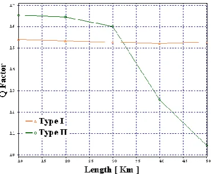
[image:2.595.330.543.90.264.2] [image:2.595.321.544.322.497.2]Case A: The simulative results have been obtained and discussed in this section for Type I and Type II configurations as depicted in Fig 2-5 on the performance metrics viz. eye-closure, Q factor, BER and received output power. From Fig 2, Q Factor (Type I) is calculated as [15.35 dB, 15.30 dB, 15.20 dB] at different optical spans of [20 km, 30 km, 40 km] respectively. On the other hand, for Type II configuration, the Q-Factor is calculated high as compare to Type I up to an optical span of 30 Km but reduces gradually and is calculated as 10.5 after an optical span of 50 Km. The Q factor for Type I remain almost stable i.e. showing a reduced amount of variations in Q factor along with variations in optical span. Further, Type I configuration exhibits the acceptable BER at optimum decision threshold up to 50 Km of optical span while Type II becomes unstable as depicted in Fig 3. The optical power received for Type I configuration is around 24 dBm, but for Type II, it is calculated as 10 dBm only as shown in Fig 4. From Fig 5, the variation in eye closure is fewer up to 30 Km and then, increases with optical span for Type II, but, for Type I, it remains almost steady. The stable Q Factor, less BER, less eye-closure and more received optical power can be attributed to the fact that Type I configuration is dominating over Type II configuration.
Fig 2: Evaluation of Q Factor vs optical span incorporating Type I and Type II configurations
[image:2.595.71.278.498.669.2]Fig 3: Evaluation of Output power vs optical span incorporating Type I and Type II configurations
Fig 4: Evaluation of BER vs optical span incorporating Type I and Type II configurations
[image:2.595.336.541.554.727.2]Case B:The simulative results, as depicted in Fig 6-9, have been obtained in this case for Type III and Type IV configurations. From Fig 6, Q Factor (Type III) is calculated as [28.40 dB, 27.89 dB, 27.50 dB] at different optical spans of [20 km, 40 km, 60 km] respectively. On the other hand, for Type IV configuration, the low Q-Factor is calculated as compare to Type III and decreases continuously to 14 after an optical span of 50 Km. The Q factor for Type III remains almost stable i.e. showing a reduced amount of variations along with variations in optical span. Further, Type III configuration also, exhibits the acceptable eye closure up to 50 Km while Type IV shows high eye closure as depicted in Fig 7. The optical power received for Type III configuration is around 3.75 dBm, but for Type IV, it is calculated as 1.45 dBm at an optical span of 90 Km as shown Fig 8. From Fig 9, eye opening decreases with optical span and is high for Type III with values 0.025 and 0.012 for Type III and Type IV respectively. Therefore, Type III can be used for far long haul optical communication. The more Q Factor, less eye-closure, more eye opening and more received optical power can be attributed to the fact that Type III configuration is dominating over Type IV configuration. We can attribute to the fact that FRA as pre amplifier (Type III) gives best results as compared to FRA used as post amplifier (Type IV).
Fig 6: Evaluation of Q Factor vs optical span incorporating Type III and Type IV configurations
Fig 7: Evaluation of Eye closure vs optical span incorporating Type III and Type IV configurations
[image:3.595.325.543.321.496.2]Fig 8: Evaluation of Output power vs optical span incorporating Type III and Type IV configurations
Fig 9: Evaluation of Eye opening vs optical span incorporating Type III and Type IV configurations
[image:3.595.74.276.348.503.2] [image:3.595.68.280.562.732.2]opening and more received optical power are interestingly found to be in Type V configuration.
Fig 10: Evaluation of Q Factor vs optical span incorporating Type V and Type VI Configuration
Fig 11: Evaluation of BER vs optical span incorporating Type V and Type VI configurations
[image:4.595.74.270.119.282.2][image:4.595.67.271.341.501.2]
Fig 12: Evaluation of Output power vs optical span incorporating Type V and Type VI configurations
Fig 13: Evaluation of Eye opening vs optical span incorporating Type V and Type VI configurations
3.
CONCLUSION
From results obtained in this work, we draw some important conclusions. In case A, Type I provide high received power, high Q factor and low BER than Type II configuration due to the severe impact of SBS scattering in later configuration. Further, in case B, it is also observed that Type III configuration performs better than Type IV by providing high Q factor, high received output power, and large eye-opening to implement such optical systems feasible. In case C, FRA amplifier acts as preamplifier in association with SOA (Type V) performs better than Type VI configuration employing FRA as post amplifier in association with SOA. Out of all possible configurations discussed in this work, Type III performs better and is recommended to use in long-haul optical communication systems.
4.
REFERENCES
[1] H. Masuda, “Review of wideband hybrid amplifiers,” Technology Digest OFC’00, 2000, 2-4
[2] P. B. Hansen, L. Eskildsen, S. G. Grubb, A. J. Stentz, T. A. Strasser, J. Judkins, J. J. DeMarco, R. Pedrazzani, and D. J. DiGiovanni, “Capacity upgrades of transmission systems by Raman amplifier,” IEEE Photonic Technology Letter, 1997,volume 9, 262-264
[3] A. Carena and P. Poggiolini, “On the Optimization of Hybrid Raman/Erbium-Doped Fiber Amplifiers” IEEE Photonics Technology Letters, 2001, volume 13, no. 11 [4] M.-S. Kao and J. Wu, “Extending transmission distance
of high-density WDM systems using post transmitter fiber Raman amplifiers,” Journal Lightwave Technology, 1991, volume 9,. 394-399
[5] D. N. Christodoulides and R. B. Jander, “Evolution of stimulated Raman crosstalk in wavelength division multiplexed systems”, IEEE Photonic Technology Letter, 1996, volume 8, 1722-1724
[image:4.595.79.268.560.724.2][7] M. N. Islam, “Raman amplifiers for telecommunications”, IEEE Journal Selected Topics in Quantum Electron”, 2002, volume 8, no. 3, 548-559 [8] J. Bromage, “Raman amplification for fiber
communications systems”, Journal Lightware Technology, 2004, volume 22, no. 1, 79-93
[9] D. Garbuzov, R. Menna, A. Komissarov, M. Maiorov, V. Khalfin, A. Tsekoun, S. Todorov, and I. Connolly, “1400-1480 nm ridge waveguide pump lasers with 1 watt CW output power for EDFA and Raman amplification”, in Proceedings of Optical Fiber Communications Conference, Anaheim, CA, 2001, PD-18-1-PD-18-3 [10] John N. Senior “Optical Fiber Communications
principles and practice”, New Delhi, 2005.
[11] H. S. Seo, Y. G. Ghio, and K. H. Kim “Design of transmission optical fiber with a high Raman gain, large effective area, low nonlinearity, and low double Raleigh back scattering ”, IEEE photonic technology letter, 2004, volume 16
[12] Jin Shangzhong et.al “Research of Gain and Bandwidth in Hybrid Fiber Raman Amplifier” ACTA PHOTONICA SINICA, 2004, volume 33, no. 4