Volume 50– No.17, July 2012
Modifications in IEEE 802.11 to Prevent Collisions due to
Interference in MANETS
R. K. Manocha
Institute of Management
Studies, Lal Kuan, Ghaziabad,
U.P. 201009,
India
R.P. Agarwal
Shobhit University, Meerut,
U.P., 201010
India
Anoop Srivastava
Institute of Engineering &
Technology, Alwar, Rajasthan
India
ABSTRACT
Collisions due to interference signal are frequent in multi-hop wireless networks. Interference signal can be reduced below a threshold level if all parallel transmitter-receiver pairs maintain a minimum of „safe-distance‟ between them. A node observes a „significant‟ sudden increase or decrease in its received signal whenever another node within its „safe-distance‟ begins or ends its transmission. Thus, if any node observes a sudden increase in its received signal by more than the „significant‟ value, it infers that another node within its „safe-distance‟ has begun its transmission. Similarly, when any node observes a sudden decrease in its received signal by more than the „significant‟ value, it infers that another node within its „safe-distance‟ has completed its transmission. In this paper we propose a protocol where a node begins its transmission only if it has a minimum of „safe-distance‟ from the nearest parallel transmitter-receiver pair, and compute the values of „safe-distance‟ and the „significant‟ change in received signal. We then propose modifications in IEEE 802.11 protocol such that every node ensures a minimum of „safe-distance‟ from the nearest transmitter-receiver pair before it begins its transmission. Analysis shows that when all receivers in the network have a Signal to Interference & Noise Ratio SINR ≥ β, collisions due to interference can be completely prevented. It also brings out the situations where interference might exceed 1/β-N; however, the probability of interference exceeding 1/β-N lies between 0 and 0.1577*10-5
.
General Terms
Wireless multi-hop networks, Ad hoc networks.
Keywords
Keywords are your own designated keywords which can be used for easy location of the manuscript using any search engines.
1.
INTRODUCTION
Collisions while Data transfer are common in multi-hop wireless networks. These are classified as direct collision and indirect collision. When more than one node within each other‟s transmission range, start their frames at same time, a direct collision is said to have occurred and when collision occurs due to interference, an indirect collision is said to have occurred. Interference signal at a node is the received signal due to other parallel transmitters in the network. If P is power at which a transmitter operates and „d‟ distance between a receiver and transmitter, then
Signal at the receiver = G.P/dα. ………..(1) where G is the constant of proportionality, and α is the „propagation constant‟. Total interference „I‟ due to parallel transmitters at any receiver in the network must be such that SINR ≥ β, that is,
S/(I+N) ≥ β ……….... (2)
where S is the signal at the receiver due to the intended transmitter and N is ambient noise in the network.
By using equations (1) & (2), it is possible to compute the maximum permissible value of „I‟ at any receiver for different values of α, β, N and a set of parallel transmitters. Let „safe-distance‟ be the minimum distance between any two transmitter-receiver pairs operating in parallel in the network such that the interference for all receivers in the network satisfies S/(I+N) ≥ β, then there would be no collisions due to interference. Thus, there is a need for a protocol that restricts every node to begin its transmission only if it has a minimum of „safe-distance‟ from the nearest parallel transmitter. This paper aims to (i) quantify „safe-distance‟ between any two parallel transmitter-receiver pairs for design values of α, β, N, and the maximum number of parallel transmitters in the network, and (ii) help every node to estimate its distance from the nearest parallel transmitter-receiver pair. The rest of the paper has been organized as: section 2 gives the related works, section 3 discusses the challenges for estimation of „safe-distance‟, section 4 has details of strategy of proposed solution and proposed protocol, section 5 enlists and analyses possibilities of failures and computes the probability for each of these possibilities, and conclusions are discussed in section 6.
2.
RELATED WORK
Multiple papers are available in published literature relating to mitigate the interference. In [1], authors used cognitive radio technology and identify the vacant channels in order to alleviate the impact of interference. In [2], authors analyzed the strongest interference component by having a Channel State Information (CSI), and by using multiple antennas, apply zero-forcing beam-forming at each receiver for canceling the strongest interferers. The authors also suggested that this scheme is suitable for MANETs with single-stream data links and perfect synchronization between nodes. In [3], authors proposed a scheme MUD-MAC for “soft interference cancellation”. Here authors also suggested modification in functionalities of both medium access control and physical layer so that these complement each other with an emphasis on iterative multi-user detection. However, this scheme requires frame level synchronization and would increase the time required to perform the necessary decoding. In [4], authors use directional antennas to limit the effect of interference. In [5] authors have reported that graded SINR model with SINR ≥ 6dB would reduce the packet drop ratio to ≈0% whereas in [6] authors have reported that SIR ≥ 6dB would reduce the packet drop ratio below 10% due to interference.
its transmission. In this paper, authors have presented a protocol where every transmitter and receiver individually ensures a minimum of „safe-distance‟ from its nearest parallel transmitter-receiver pair before beginning their transmission.
3.
CHALLENGES
Two main challenges are: first, a node cannot estimate the number and the distances for current transmitter-receiver pairs in the network; second, a node can estimate a distance equal to transmission range only and not beyond it. In this paper all distances have been normalized with transmission range „r‟, which is assumed to be same for all nodes.
4.
PROPOSED SOLUTION
Let us assume that all nodes in the network transmit with omni-directional antennas at same power level and have transmission range as one unit distance. Let the „safe-distance‟ be expressed as „a‟ times the transmission range of a node, where „a‟ is a constant; its value has been computed in later part of this section. A node before beginning its RTS or CTS frame should ensure a minimum of „safe-distance‟ from the nearest parallel transmitter-receiver. Whenever a node Ti begins its RTS or DATA frame, a node „T‟ at less than „safe-distance‟ from it would observe a sudden increase in its received signal of magnitude > 1/aα; refer equation (1), for brevity, the constant of proportionality has been replaced by one at all references in this paper, and the value 1/aα has been referred to as Magnitude2 in the remaining part of this paper. Generally, „T‟ would observe two positive jumps > Magnitude2 due to each Ti or Ri at less than „safe-distance‟ from it; for Ti two positive jumps are due to beginning of RTS and DATA frames, and similarly two positive jumps are due to beginning of CTS and ACK frames by Ri. Thus, for any Ti-Ri pair, „T‟ may observe 2 or 4 positive jumps > Magnitude2. If „T‟ begins a timer with the first (odd) positive jump > Magnitude2 due to a node Ti and resets the same with second (even) negative jump > Magnitude2, then „T‟ can be sure that node Ti at less than „safe-distance‟ from it has completed its transmission. If „T‟ has no active timer and does not observe a jump > Magnitude2 for DIFS+CW period, where DIFS and CW have the same meaning as used in IEEE 802.11, then „T‟ can begin its RTS if it has data to transmit.
„T‟ can start multiple timers if nodes Ti, Tj, Tk … at less than „safe-distance‟ from it begin their frames with a little time gap; however, it cannot correlate the timers to nodes.
When multiple nodes at ≥ „safe-distance‟ from „T‟ start their frames at same time such that „T‟ observes a positive jump > Magnitude2, it would start a new timer if it is an odd positive jump. Such cases are known as False Positives. Similarly, when multiple nodes at ≥ „safe-distance‟ from „T‟ complete their frames at same time such that „T‟ observes a negative jump > Magnitude2 in magnitude, „T‟ would reset one of its oldest timers, if any, if it is an even negative jump. However, a False Negative may not be associated with a False Positive as there is remote probability of nodes having their DATA frames of same size; therefore, „T‟ waits till all its timers‟ time-out before beginning its RTS frame. It is a penalty every node has to pay for False Positive as the protocol cannot differentiate between jumps > Magnitude2 due to one node at < „safe-distance‟ and by multiple nodes at ≥ „safe-distance‟. False Negatives have been discussed at length in section V. „T‟ would start „k‟ timers at same time if the magnitude of odd positive jump is k time‟s Magnitude2, where „k‟ is an integer. However, „T‟ would reset one timer only for an even
negative jump > Magnitude2, irrespective of the magnitude of negative jump. If „T‟ starts three timers when Ti at < „safe-distance‟ from it begins its frame and subsequently „T‟ observes one „False Negative‟ due to multiple nodes at > „safe-distance‟ from it, then it would reset only one timer with a negative jump. In this way „T‟ can partially cancel out the effects of „false negatives‟.
It is possible that a positive jump > Magnitude2 at „T‟ due to node Ti may coincide with a negative jump due to node Tj such that the net jump observed by „T‟ is < Magnitude2 and hence „T‟ does not start any timer. In such a case „T‟ may begin its transmission in parallel with a node Ti at < „safe-distance‟ from it. Such a case has been analyzed in section 5-5. Similarly a negative jump > Magnitude2 due to node Ti may occur at same time when a positive jump due to node Tj at > „safe-distance‟ occurs such that „T‟ does not observe a negative jump > Magnitude2. In such cases „T‟ can begin its frame only when all its timers time out.
4.1
Computation of ‘Safe-Distance’
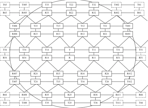
The number of parallel transmitter-receiver pairs in the network would be maximum if all transmitters maintain an exact distance of „a‟ from their nearest parallel transmitters. Figure 1 shows positions of maximum parallel transmitter-receivers pairs around a T-R pair at the centre of the network; all receivers have a distance of one unit from their respective transmitters. Interference at receiver „R‟ would be maximum when the following conditions are satisfied: (i) all parallel transmitters and receivers are separated by an exact „safe-distance‟ from their nearest neighbor transmitting in parallel, and (ii) all nodes which are transmitting their frames currently have minimum distance from „R‟, and (iii) „R‟ is almost at centre of the network, as the interference would decrease as one moves towards the perimeter of the network. Figure 1 shows an arrangement of nodes such that all parallel Ri have lesser distance from „R‟ as compared to their Ti and for computation of interference at „R‟, it is assumed that all parallel Ri are transmitting their frames, (CTS or ACK). Interference at R due to any Ri can be expressed as a function of „a‟ and α by using equation (1), subject to the condition that signal is more than the sensitivity of the receiver „R‟, which is assumed to be same for all receivers in the network. Thus, maximum interference at „R‟ due to parallel receivers which produce a signal > sensitivity level of „R‟, namely R11 to R16, R21 to R26 and R31 to R36 as shown in figure 1 can be expressed as a function of „a‟ and α as
Maximum I at „R‟ = 4/aα
+ 2/{√((a/2)^2+(√3a/2+1)^2)}α + 2/(a√3)α + 1/{a√3+1}α + 1/{a√3+2}α + 2/{√((1.5a)^2 +
(√3a/2+1)^2)}α
+ 2/{2a}α + 2/{√(a^2+(a√3+1)^2)}α + 2/{√(a^2+(a√3+2)^2)}α --- (3)
The first term in equation (3) is due to R11, R14, R15 and R16; second term is due to R12 and R13; third term is due to R25 and R26; fourth term is due to R25, fifth term is due to R22, sixth term is due to R21 and R23, seventh term is due to R31 and R34, eighth term is due to R35 and R36 and the ninth term is due to R32 and R33. If signal at „R‟ due to any Ri is less than the sensitivity of the receiver, then those terms must be dropped. More terms for transmitters T401 to T412, T51 to T56 and so on can be added in equation (3) if sensitivity of the receivers is lower than 0.004 (-23.979 dBm). Total interference at „R‟ due to all parallel receivers Ri should be ≤ 1/β-N as per equation (2).
Volume 50– No.17, July 2012
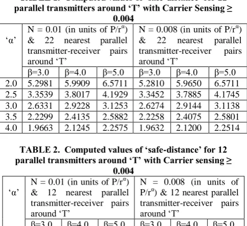
TABLE 1. Computed values of ‘safe-distance’ for 22 parallel transmitters around ‘T’ with Carrier Sensing ≥
0.004
„α‟
N = 0.01 (in units of P/rα) & 22 nearest parallel transmitter-receiver pairs around „T‟
N = 0.008 (in units of P/rα) & 22 nearest parallel transmitter-receiver pairs around „T‟
β=3.0 β=4.0 β=5.0 β=3.0 β=4.0 β=5.0 2.0 5.2981 5.9909 6.5711 5.2810 5.9650 6.5711 2.5 3.3539 3.8017 4.1929 3.3452 3.7885 4.1745 3.0 2.6331 2.9228 3.1253 2.6274 2.9144 3.1138 3.5 2.2299 2.4135 2.5882 2.2258 2.4075 2.5801 4.0 1.9663 2.1245 2.2575 1.9632 2.1200 2.2514
TABLE 2. Computed values of ‘safe-distance’ for 12 parallel transmitters around ‘T’ with Carrier sensing ≥
0.004
„α‟ N = 0.01 (in units of P/r
α
) & 12 nearest parallel transmitter-receiver pairs around „T‟
N = 0.008 (in units of P/rα) & 12 nearest parallel transmitter-receiver pairs around „T‟
β=3.0 β=4.0 β=5.0 β=3.0 β=4.0 β=5.0 2.0 4.7014 5.4955 6.2072 4.6862 5.4717 6.1734 2.5 3.2775 3.7167 4.1004 3.2690 3.7037 4.0824 3.0 2.5933 2.8795 3.1253 2.5877 2.8711 3.1138 3.5 2.2076 2.4135 2.5882 2.2036 2.4075 2.5801 4.0 1.9663 2.1245 2.2575 1.9632 2.1200 2.2514
4.2
Proposed Protocol
Every node in the network performs the following tasks whenever it observes an absolute positive or negative jump > Magnitude2 in its received signal, i.e., I+N. Further, the protocol requires two flags, termed as flag1 and flag2 with every node as described below.
1. Whenever any node observes an odd (1st or 3rd or 5th) positive jump > Magnitude2 and the frame is not addressed to it, it starts a timer for period RTS + CTS + DATA(Max) +ACK + 3SIFS and also sets flag1, where DATA(Max) is the time to transmit the longest DATA frame, SIFS is Short Inter-Frame Space as used in IEEE 802.11. If positive jump is > k*Magnitude2, then node starts „k‟ timers where „k‟ is an integer. Whenever any node observes the even (2nd or 4th or 6th) positive jump, it resets flag1. Thus flag1 is used only to indicate even or odd positive jump > Magnitude2.
2. Whenever any node observes an odd negative jump > Magnitude2, it sets flag2; for even negative jump of magnitude > Magnitude2, it resets flag2 and its oldest timer, if any.
3. Timers of any node can either time out or are reset due to negative jumps > Magnitude2. A node starts its transmission only if it has no active timer and does not observe a jump > Magnitude2 for a continuous period of DIFS+CW, where DIFS and CW have the same notation as used in IEEE 802.11. If the node observes a positive jump > Magnitude2 during DIFS+CW period, it has to start another wait for period of DIFS+CW afresh; however, if the node has already waited for some slots of CW, then reduced CW would be used for the next wait cycle as is done in IEEE 802.11.
4. When a node resets its last active timer or the last timer times out, then both the flags, i.e., flag1 and flag2 are also reset. This would help in restoration of correct status of flags when a node observes odd number of False Positives or negatives.
5. Whenever a direct collision occurs, exponential back-off as used in IEEE 802.11 is applicable for CW.
6. A node does not start any timer when it is in the process of transmitting or receiving its DATA or ACK frame.
Magnitude2 can be computed as 1/aα from design values of „a‟ and α.
4.3
Illustration
The design value of „α‟ should be the lowest value expected in any part of the network as „a‟ increases sharply and non-linearly for low values of „α‟; refer tables 1 and 2, the value of „a‟ decreases sharply as one moves from row one to row five in each of the columns. Similarly, N, i.e., Noise should be the highest value expected in any part of the network as „a‟ increases non-linearly with increasing N; compare the values in column1 with column 4 for each row of tables 1 and 2. Value of β should be large enough to maintain a low (acceptable) packet drop ratio as has been suggested in [5]; SINR of 6dB would imply β > 3.98. Thus, for illustration we have taken α=2, β=4, N=0.008, receiver sensitivity as 0.004, the transmission range of every transmitter as 200m for a circular ad hoc network of 2 Km. radius. For these design values, an estimate for „a‟ can be obtained from table 1 as 5.9650. This would allow 22 parallel transmitter-receiver pairs excluding a T-R pair at centre of network, as shown in figure 1; the 22 parallel transmitters are T11 to T16, T21 to T26, T31 to T36, T401, T406, T407 and T412. Radius of the network for these 22 parallel transmitters is ≈2.67*a, refer figure 1. Thus radius of network should be ≈200*2.67*5.9650, i.e., 3.181 Km. Since given network has a radius of 2 Km only, so reducing the number of parallel transmitters to 12 will yield a lower value of „a‟ as 5.4717, refer Table 2, and minimum radius of the network as ≈√3a, refer figure 1. This revised value of „a‟ would require the radius of network as ≈200*√3*5.4717, i.e., 1.895 Km., which can be acceptable.
Shape of the network would guide us as to the maximum number of parallel transmitters it can accommodate if it does not have a circular shape. Magnitude2 for the design value of „a‟ can be computed as 1/aα
= 0.033401.
5.
ANALYSIS
parameters can be obtained from Table 1 row 1 column 5 as 5.9650 and therefore, the Magnitude2 can be computed as 1/aα = 0.028105.
5.1
Scenario for analyzing the effect of
False Negatives
Figure 1 shows positions of maximum number of parallel transmitter-receiver pairs in a network around a node „T‟ located at its centre when all such pairs have an exact distance equal to „safe-distance‟ from their nearest pair. This does not imply that nodes have to be placed at these positions only; in real life the parallel transmitter-receiver pairs would be separated by a distance larger than the „safe-distance‟ from each other and many other nodes would be located in intervening distance. This placement of parallel transmitter-receiver pairs is considered in order to have the maximum interference at a receiver located very close to the centre of the network. If either the actual number of parallel transmitter-receiver pairs is less than the maximum number permissible in network, or the nearest parallel transmitter-receiver pair is located at more than the „safe-distance‟, then the total interference at any receiver in the network would be below 1/β-N, which implies no collisions would take place due to interference. Further, the interference would be maximum at nodes close to the centre of the network. With reference to figure 1, assume that nodes T and R are not engaged in any data transfer and a node Tx is located at a distance of f*a from „T‟ in the direction of T11, where „f‟ lies between 0 and 1, and similarly its Rx is located at a distance of f*‟a‟ from R towards R11. Further, assume that T11-R11 pair begins its data transfer followed by T16 and R16 pair, followed by T12 and R12 pair at short intervals one by one such that all these pairs are operating in parallel. As these three transmitter-receiver pairs begin their frames, Tx would start its first timer due to T11 and another timer due to R12; notice that Tx does not start a second timer when it observes a positive jump > Magnitude2 due to R11, refer figure 2; the value of „a‟ and Magnitude2 are the same as mentioned above in section 5. Similarly Rx would start its first timer as T11 begins its RTS frame and second timer when R16 begins its CTS frame. When Tx observes a negative jump > Magnitude2 due to CTS by R11, it would reset its first timer as it is the second negative jump > Magnitude2; Tx observed first negative jump > Magnitude2 with negative edge of RTS by T11, refer figure 2. Further assume that the remaining parallel transmitter pairs as marked in figure 1 also begin their transmission one by one at a time without affecting the timers of Tx and Rx. At this state, further assume that two nodes at greater than „safe-distance‟ from Tx complete their frames at same time such that Tx observes a False Negative, and therefore, resets its only active timer and begins its transmission in parallel with the existing parallel transmitter-receiver pairs after a delay of DIFS. In this configuration we have maximum number of parallel transmitter-receiver pairs and all parallel receivers have minimum distance from Rx and all it is assumed that all receivers are active such that interference at Rx is maximum so that the probability of collisions due to interference is maximum.
5.2
Identification of pair nodes that can
generate a ‘False negative’ at Tx
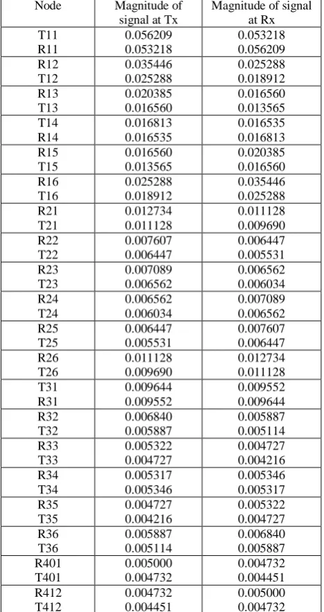
The magnitude of signal at Tx and Rx due to every Ti and Ri operating in parallel as shown in figure 1 and produce a signal > minimum carrier sensing signal of 0.004 at Tx and Rx for α=2, β=4, N=0.008, „f‟=0.292893 has been computed by using equation (1) and compiled in Table 3; notice that all parallel receivers have shorter distance from Rx as compared to their respective transmitters; the value of „f‟ = 0.292893
produces a jump of 2.0 times the Magnitude2 at Tx as 1/(1-f)2 = 2.0.
TABLE 3. Magnitude of signal at Tx & Rx due to 20 parallel transmitter-receiver pairs for α=2, β=4, N=0.008,
f=0.292893, carrier sensing signal=0.004, all parallel receivers have minimum distance from Rx, and R11 and
R16 are at < ‘a’ distance from Rx; ‘a’=5.9650, Magnitude2=0.028105, RT=0.269766
Node Magnitude of signal at Tx
Magnitude of signal at Rx T11 R11 0.056209 0.053218 0.053218 0.056209 R12 T12 0.035446 0.025288 0.025288 0.018912 R13 T13 0.020385 0.016560 0.016560 0.013565 T14 R14 0.016813 0.016535 0.016535 0.016813 R15 T15 0.016560 0.013565 0.020385 0.016560 R16 T16 0.025288 0.018912 0.035446 0.025288 R21 T21 0.012734 0.011128 0.011128 0.009690 R22 T22 0.007607 0.006447 0.006447 0.005531 R23 T23 0.007089 0.006562 0.006562 0.006034 R24 T24 0.006562 0.006034 0.007089 0.006562 R25 T25 0.006447 0.005531 0.007607 0.006447 R26 T26 0.011128 0.009690 0.012734 0.011128 T31 R31 0.009644 0.009552 0.009552 0.009644 R32 T32 0.006840 0.005887 0.005887 0.005114 R33 T33 0.005322 0.004727 0.004727 0.004216 R34 T34 0.005317 0.005346 0.005346 0.005317 R35 T35 0.004727 0.004216 0.005322 0.004727 R36 T36 0.005887 0.005114 0.006840 0.005887 R401 T401 0.005000 0.004732 0.004732 0.004451 R412 T412 0.004732 0.004451 0.005000 0.004732
From the values in Table 3 column 2 it is possible to form pairs of nodes which produce a „false Negative‟ at Tx. With the computed value of „a‟ for the said parameters, node T12 does not produce a jump > Magnitude2 at Tx, whereas, node R12 produces a jump > Magnitude2 at Tx, refer figure 1. Similarly, R16 produces a jump > Magnitude2 at Rx but T16 does not produce a jump > Magnitude2 at Rx. The list of node pairs where Ti and Ri both produce a „false negative‟ at Tx should exclude T12-R12 and T16-R16.
[image:4.595.315.549.167.609.2]Volume 50– No.17, July 2012
The list of pair of nodes that can generate a „false negative‟ at Tx can be grouped in two ways, first group consists of pairs formed from nodes T13, R13, T14, R14, T15 and R15 only, and the second group consists of pairs formed by one node from the above said six nodes and another node out of T21 to T26, T31 to T36, T401, T406, T407, T412, R21 to R26, R31 to R36, R401, R406, R407, R412. Each of the two groups can be further subdivided as a pair of transmitters Ti and Tj, or as a transmitter Ti and a receiver Rk, or as a pair of receivers Ri and Rk. This sub-division yields 7 different options of generating a „false negative‟ at Tx by exactly two nodes and these have been listed in Table 4.
Table 4. Various options for generating a ‘False negative’ at Tx when two nodes complete their frames exactly at same time for α =2.0, β = 4, N=0.008, f=0.292893, carrier
sensing signal = 0.004, and all 20 parallel receivers have minimum distance from Rx, ‘a’=5.9650;
Magnitude2=0.028105; RT=0.269766.
Option Nodes which complete their frames at same time and can generate a „False Negative‟ at Tx. (i) Ti ∩ Tj
i = 13, 14, 15 j≠i, j = 13, 14, 15. (ii) Ti ∩ Rk
i = 13,14,15, k≠i, k = 13, 14, 15. (iii) Ti ∩ Rk
i = 13, 14, k = 21 (iv) Rk ∩ Ti
k=13, i=21, 26, 31.
(v) Ri ∩ Rk
i=13, 14, 15, k≠i, k = 13, 14, 15 (vi) Ri ∩ Rk
i=13, k = 21, 26, 31. (vii) Ri ∩ Rk
i=14, 15, k = 21
5.3
Time slots when Tx can begin its frame
in parallel with other 20 pairs after one
‘false negative’
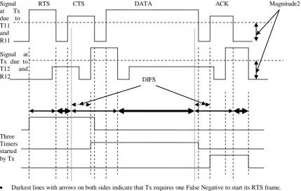
As T11 begins its RTS frame, Tx starts its first timer; let this time be referred to as T0. T16 and R16 are at > „safe-distance‟ from Tx, hence neither RTS or CTS would create a jump > Magnitude2 at Tx. T12 starts its RTS frame after a period of δ from T0. Since distance between Tx and T12 is more than „safe-distance‟, so Tx does not observe a jump > Magnitude2 due to RTS by T12. From the time T0 until the negative edge of RTS by T11, Tx would require two „false negatives‟ in quick succession in order to reset its only timer and start its RTS frame in parallel with other nodes. Tx would observe even (second) positive jump > Magnitude2 as R11 begins its CTS, refer figure 2 and odd (third) positive jump > Magnitude2 as R12 begins its CTS. If Tx observes one „false negative‟ after T11 completes its RTS frame and until DIFS period before positive edge of CTS by R12, then Tx can start its RTS frame in parallel with T11, T12 and other nodes. This period has been marked in figure 2 by a heavy horizontal line with arrows at both ends.
Tx would require two „false negatives‟ during a period beginning with DIFS period before the positive edge of CTS by R12 till the negative edge of CTS by R12 to start its RTS frame in parallel with T11, T12 and other nodes; refer figure 2. After R12 completes its CTS, Tx would require one „false negative‟ until DIFS period prior to beginning of ACK by R11 to reset its only active timer. Tx would again require two
„false negatives‟ thereafter till R11 completes its ACK. Further, Tx would require one „false negative‟ from thereafter till R12 completes its ACK frame as shown in figure 2. Let DATA11 and DATA12 be the DATA frame transmission time for nodes T11 and T12 respectively. If DATA11 < DATA12+δ, then the number of slots when Tx requires one „false negative‟ to begin its RTS frame in parallel with other transmitter-receiver pairs is three, else there are two slots, refer figure 2. If δ represents the delay by which T12 starts its frame after T11, then total time „t‟ of the said two or three slots when Tx can begin its frame after one „false negative‟ during a cycle of RTS, CTS, DATA and ACK is as given below:
If SIFS + δ > DIFS
If DATA12+δ ≥ DATA11
„t‟=DATA12+3SIFS-2DIFS+δ Else
„t‟= DATA11+3SIFS-2DIFS-δ Else
If DATA12+δ < DATA11 „t‟=DATA12+2SIFS Else
„t‟=DATA11+2SIFS-DIFS.
5.4
Computation of probability for
situations when interference exceeds 1/β-N
due to ‘false negative’
A „False Negative‟ by Ti-Tj pair of nodes can be generated in three ways, (i) negative edges of RTS frames by Ti and Tj coincide, (ii) negative edges of RTS and DATA frames by Ti and Tj or vice versa coincide, and (iii) negative edges of DATA frames by Ti and Tj coincide.
If Tx observes a „false negative‟ due to coinciding negative edges of RTS frames by Ti and Tj nodes at > „a‟ distance from Tx, then it must have observed a positive jump > Magnitude2 when Ti and Tj both started their RTS frame at same time. Further, after the negative edges of RTS frames, the receivers Ri and Rj would begin their CTS frames after SIFS period and these frames would also generate another positive jump > Magnitude2 at Tx; In order to maximize interference at Rx it is assumed that all parallel receivers have lesser distance from Rx as compared to their transmitters, therefore, Ri and Rj both would generate a positive jump > Magnitude2 at Tx. Thus, Tx must start a new timer with either beginning of RTS frames by Ti and Tj or with beginning of CTS frames by Ri and Rj Thus, a false negative at Tx by coinciding edges of RTS frames by Ti and Tj forces Tx to start a new timer, therefore, Tx cannot begin its RTS frame before the new timer is also reset or times out. Moreover, negative edges of CTS by Ri and Rj would also generate a „false negative‟ at Tx, but this would be the first negative jump for the new timer of Tx and it requires second negative jump to reset the timer. Further, Tx would observe another (third) „false positive‟ after SIFS period due to beginning of DATA frames by Ti and Tj, forcing it to start another timer. Hence, Tx cannot begin its frame if it observes a „false negative‟ by coinciding RTS edges.
timer, which implies that it cannot begin its transmission in parallel with other nodes.
Ti and Rk pair of nodes can generate a „False Negative‟ at Tx in four ways, when negative edges of: (i) RTS frame by Ti and CTS frame by Rk coincide, or (ii) RTS frame by Ti and ACK frame by Rk coincide, or (iii) DATA frame by Ti and CTS frame by Rk coincide, or (iv) DATA frames by Ti and ACK frame by Rk coincide. Ti and Rk combination of nodes appears in Table 4 at three options, namely (ii) to (iv). For all these three options, interference at Rx may exceed 1/β-N. The probability of occurrence of these three options can be computed as (1/7)*(1/34)*(1/32)*(3*2 + 2*1 + 1*3); the terms 1/34 and 1/32 are for selection of Ti and Rk out of 17 pairs of transmitters and receivers; From the entries in Table 3 one can observe that only twenty pairs would generate a signal > carrier sensing value of 0.004 at Tx or Rx, and since at least one node out of node pairs T11-R11, T12-R12 and T16-R16 produces a „true negative‟ at Tx or Rx, hence these three pairs have been excluded from the list of twenty pairs. The term (3*2+2*1+1*12) has three factors, first factor 3*2 represents possibilities of selecting Ti out of 13, 14 or 15 and Rk out of 13, 14 or 15, k≠i from option (ii), second factor 2*1 represents various possibilities of selecting Ti out of 13 and 14 and at same time selecting Rk as 21 from option (iii), the third factor 1*12 represents various possibilities of selecting Rk as 13 and at same time selecting Ti out of 21 to 26, 31 to 34, 36 and 401 from option (iv).
A „False Negative‟ by Ri and Rk pair of nodes can be generated in three ways, when negative edges of: (i) CTS frames by Ri and Rk coincide, or (ii) CTS and ACK frames by Ri and Rk or vice versa coincide, or (iii) ACK frames by Ri and Rk coincide.
When Ri and Rk generate a „false negative‟ by completing their CTS frames, then Tx must have observed a „false positive‟ at the beginning of CTS frames. With reference to figure 2, there are two main slots where Tx requires one „false negative‟ to begin its transmission in parallel with other nodes. If Ri and Rk generate a „false positive‟ by their CTS frames before the first slot of generating a „false negative‟, then Tx would observe its third „false positive‟ after SIFS period due to beginning of CTS frame by R11 thus preventing Tx to begin its transmission. If Ri and Rk generate a „false positive‟ by their CTS frames before the second slot of generating one „false negative‟, then Tx would observe its fourth „false positive‟ due to coinciding positive edges of CTS and fifth positive jump due to beginning of DATA frame by T11 thus preventing Tx to begin its transmission. Therefore, if Ri and Rk generate „false negative‟ by their CTS frames, then there would be no collision due to interference.
If both Ri and Rk use ACK frames to generate a „false negative‟ at Tx, then the beginning of ACK frame would have produced an odd „positive jump‟ at Tx, forcing it to start a new timer, and therefore, Tx cannot begin its transmission after DIFS period; this is similar to case of „false negative‟ by coinciding CTS frames.
When Ri and Rk nodes generate a „false negative‟ at Tx by any combination of CTS and ACK frames and Tx starts its frame in parallel with all other possible T-R pairs, then interference at Rx would exceed 1/β-N with a probability of (1/7)*(1/34)*(1/32)*(2/4)*(3*2 + 1*3 + 2*1) for three options (iv) to (vi); the term 2/4 is due to combinations of CTS and ACK frame by Ri or Rk.
Thus, the maximum probability of collision due to interference at Rx when Tx begins its frame in parallel with other nodes is 16.5/(7*34*32) ≈ 0.0021665 multiplied by the probability that two nodes at > „a‟ distance from Tx complete
their frames at same time, multiplied by the probability that Tx can start its frame after observing one false negative, multiplied by the probability that all parallel transmitter-receivers pairs have an exact „safe-distance‟ from the nearest parallel transmitter-receiver pair as shown in figure 1, multiplied by the probability that all receivers have an exact distance of one unit from their respective transmitters. The probability of two nodes completing their frames at same time can be determined by use of geometric probability. If we assume that smallest of RTS, CTS, DATA and ACK frames is of 200μs, then the probability that two nodes would complete their frames at same time is 1 – (199/200)2 = 0.009975. If the frame size is larger than 200μs, then the probability decreases. If we assume that approximate values of RTS, CTS, ACK, DATA11, SIFS and DIFS are 200, 200, 200, 2000, 10 and 50μs respectively, then the probability that Tx observes a „false negative‟ during the said period is 0.7338 for small values of δ and equal DATA frame size for T11 and T12. Maximum interference at Rx is the sum of values in column 3 of Table 3 due to all parallel receivers and equals 0.269766. If the distance between a transmitter and its receiver is ≤0.0949 for Rx, then sum of interference and noise would always be ≤ 1/β. The probability that a receiver lies outside 0.949 distance from its transmitter is 1-(0.949)2=0.099399.
Thus, net probability of collision due to interference is 0.0021665 * 0.009975 * 0.7338 * 0.099399 = 0.15763*10-5 multiplied by the probability that all parallel transmitter-receivers pairs have an exact „safe-distance‟ from the nearest transmitter-receiver pair as shown in figure 1.
5.5
Coinciding Positive and Negative
jumps
When a negative jump larger than Magnitude2 due to a node Ty at less than „safe-distance‟ from Tx coincides with a positive jump due to a node Tz at more than „safe-distance‟ from Tx, such that Tx observes a net jump less than Magnitude2, then Tx would not reset any of its timer. If Tx has only one timer, then that timer must time out before Tx can begin its transmission.
However, if a positive jump due to Ty coincides with a negative jump due to a node Tz, and Tx observes a net positive jump < Magnitude2, then Tx would infer that it can begin its transmission in parallel with other nodes if it has no active timers. Since the net positive jump at Tx is < Magnitude2, so Ty must be ≥ (1-0.292893)*„a‟ distance from Tx; otherwise Ty alone would have generated a positive jump of two times Magnitude2 at Tx and with a negative jump due to Tz, Tx would have observed a net jump > magnitude 2. Moreover, Ty must have a distance ≥ „a‟ from Tz otherwise Ty cannot start its frame. In order to maximize interference at Rx, Ty can be considered as equivalent to T11 which has just started its frame whereas Tz is one of Ti or Ri with i=13, or 14 or 15. The probability of collision due to interference for this case is the same as has been computed in section 5.4.
5.6
Observations:
5.6.1
Effect of ‘f’:
Volume 50– No.17, July 2012
5.6.2
Time gap after which next set of nodes can
begin their transmission when the current set of
nodes complete their transmission
Nodes which are located at a distance > 0.707107*„a‟ from the Ti-Ri pair just completing its transmission will have no active timers, as the nodes up to a distance of 0.707107*„a‟ from Ti or Ri will have at least one active timer Ri completes its ACK frame. If maximum number of parallel transmitter-receiver pairs is active, then next set of nodes that can begin their transmit in parallel only after RTS+CTS+DATAMAX+
ACK+3SIFS period as a node at > 0.707107*„a‟ from a given Ti-Ri pair would fall within same distance from another Tj-Rj pair operating in parallel.
5.6.3
When multiple nodes at ‘safe-distance’
begin their frames at same time
If more than one node T11 to T16 begins its frames at same time, then T-R pair would have to delay their transmission for RTS+CTS+DATAMAX+ACK+3SIFS period unless the frame
size of two nodes is the same.
6.
CONCLUSIONS
[image:7.595.65.568.284.651.2]From the magnitude of sudden increase or decrease in its received signal, every node infers that it has a minimum of „safe-distance‟ from the nearest node operating in parallel.A node should start its transmission only if it has a minimum of „safe-distance‟ from the nearest parallel transmitter or receiver, otherwise, it should delay its transmission till all nodes within its „safe-distance‟ complete their data transfer. Analysis shows that the collision due to interference can occur only if a node begins its transmission when it wrongly infers that no other node within its „safe-distance‟ is transmitting due to coinciding positive or negative jump due to > 1 nodes located at > „safe-distance‟ from it. The probability of collision due to interference for such cases is < 0.3*10-5. Thus, collisions due to interference at all receivers of the network can be practically prevented.
Fig 1: Placement of maximum number of parallel transmitter-receiver around a node T at the centre of the network
T
R R11 R31 R51
R14 R34
R54
T11 T31 T51
T14 T34
R16
T16 R12 T12
R26
T26
R412
T412
R36 R411
T411 T36
R21
T21 T401
R401 R402
T402
R32 T32
R15
T15
R25
T25 R24
T24
R35
T35 R408
T408 R407
T407
R13 T13
R23 T23
R22 T22
R33 T33
T406
R406
T54
R405 T405
R61 T61 T63
R63
R64
T64
R66
T66
Nodes connected with vertical lines are at distance of transmission range from each other, and Nodes connected with horizontal lines or lines at an angle are separated by an exact distance „a‟ = „safe-distance‟.
Fig 2: Number and timings of ‘False negatives’ Tx must observe before beginning its frame in parallel with other nodes.
7.
REFERENCES
[1] Refaei M. Tamer, Souryal Michael R., and Moayeri Nader; “Interference Avoidance in Rapidly Deployed Wireless Ad hoc Incident Area Networks”, In Proceedings of IEEE Infocom Workshop on Mission-Critical Networking, 2008.
[2] Kaibin H., Jeffrey A. G., Robert H. W. Jr., Dongning G., Randall B.A.; “Spatial Interference Cancellation for mobile Ad Hoc Networks: Perfect CSI”, The University of Texas at Austin, USA, April 2008. http://aps.arxiv.org/abs/0804.0813.
[3] Katsutoshi K., Robert V., Andreas M., Christian H., and Gerhard B.; “Medium Access in Spread-Spectrum Ad Hoc Networks with Multi-user Detection” Hindawi Publishing Corporation, EURASIP Journal on Advances in Signal Processing, Volume 2009, Article ID 1562472009
[4] Ghannudi H.EL, Clavier L., Rolland P.A. “Modeling Multiple Access Interference in Ad hoc Networks Based on IR-UWB Signals Up-Converted to 60 Ghz”, in Proc.
European Conf. Wireless Technologies, Munich, Oct. 2007, pp 106-109.
[5] R. Maheshwari, S. Jain, and S. R. Das. A measurement study of interference modeling and scheduling in low power wireless networks. In SenSys, pages 141–154, 2008.
[6] Sevani V., Raman B. “SIR Based Interference Modeling For Wireless Mesh Networks: A Detailed Measurement Study”, COMSNETS 2012, 4th International Conference on Communication Systems & Networks, January 3-7, 2012 at Bangalore, India.
[7] Manocha R.K., Agarwal R.P., Srivastava A. “A MAC Protocol to prevent collisions due to interference for Ad Hoc Networks” in Global Trends & Innovations in Computer Applications And Informatics – CICON- 2011, held on Sat-Sun, April 9 & 10, 2011, at the Shobhit University Campus, Meerut.
[8] Manocha R.K., Agarwal R.P., Srivastava A. “A MAC Protocol to prevent collisions due to interference for MANETS”; IJCSS, volume 2, Issue 2, Jan-June 2012. Three
Timers started by Tx Signal at Tx due to T11 and R11
Signal at Tx due to T12 and R12
RTS CTS DATA ACK Magnitude2
Darkest lines with arrows on both sides indicate that Tx requires one False Negative to start its RTS frame.
Medium dark lines with arrows on both sides indicate that Tx requires two False Negatives in succession to start its RTS frame.
Normal lines with two arrows indicate a time gap of DIFS period from the events, one from the beginning of CTS frame by R12 and the second from beginning of ACK frame by R11.