A Multi-Agent System for Image Compression
Redjimi Mohammed
Phd, department of computer sciences - University of 20 August 1955 – Skikda – Algeria
ABSTRACT
We describe, in this paper, a multi-agent system (MAS) dedicated to the compression of digital images. An Image may be considered as a matrix of N lines and of M columns, that is to say a size of NxM pixels. To each line, we associate an agent. Our approach is inspired from the RLE (Run Length Encoding) method but instead of storing the occurrences of the pixels having a same value followed by the value of these pixels, we use a labeling table which contains all the values of the pixels of the image. We obtain a compressed image as a list of color labels followed by the number of successive occurrences of this color. We observe, that, an image is made up of about thirty different colors approximately, this mean that the label of color can be coded on five bits. This method is very effective for images where the color is coded on several bytes. The algorithm is as follow: each agent traverses the image line with which it is associated by seeking for each detected color the number of its successive occurrences. The agent thus draws up a set of lists for each color found including the number of its occurrences. All the other agents carry out these tasks in parallel. It is possible to obtain images compressed without or with loss of information according to the desired quality of the compressed image. This approach allows a very great improvement of the performances in storage capacity of information (the compressed images thus obtained occupy less memory space) and in execution time (the parallel execution allows very high accelerations of the algorithms).
General Terms
Image processing, Image compression
Keywords
Digital image, image compression, agent, multi-agent system (MAS).
1.
INTRODUCTION
The image constitutes a very rich element of communication as for the quantity of information which it conveys. This information can be apprehended in a total way. The interpretation of an image can vary according to the people, their cultures, their moods, their beliefs, etc. Some elements of the image can appear ambiguous, unreal or exaggerated. The image is used everywhere; in publicity, cinema, television, mobile phones, etc. Several industries turn thanks to this concept. In the computer; [1] [2] the image is digitized; a 2-D image seems a dot matrix composed of a set of points (picture elements: pixels). An image color is stored in memory in the shape of a matrix of N lines and M columns of pixels. A point of coordinates (X,Y) is made of a combination of the three basic colors: red, green and blue. In the RGB additive model, the intensity of a pixel corresponds to the sum of the quantities of red, green and blue coded into binary (we can consider a colored image coded by using 24 bits, each basic component red, blue or green being coded on 8 bits); I(X,Y)= αR+βB+γG. Who α,β and γ represent respectively the
proportions of red, blue and green which compose the intensity of the pixel. This first approach enables us to observe that an image made up of 1024x1024 pixels will occupy a space memory of 1024x1024x24 bits (3 Mega bytes : 24 Mega bits). Moreover; these images are intended to undergo whole of treatments, being stored, filed and sent by the intermediaries of channels of communication to distant consumers. To guarantee a good quality of reception, the bandwidth of these channels must be adequate. This is not always possible or requires colossal technical investments and big costs.In order to reduce the size of the image, there exist several techniques allowing its compression [3]. These algorithms exploit a set of parameters and features of the image to code it in more condensed form. Once the image is compressed, other algorithms make it possible to restore the original image. It is necessary to notice, on this level, that we can consider two types of compression of images: compression without loss of information (lossless); in this case the restored image must be in total conformity with the original image and compression with loss of information (lossy), in this second case the restored image is not in total conformity with the original one. It may decide on the acceptable proportions of loss of information according to the scope of application for concerned system. Several domains do not require a rigorous copy of the original image but just of the elements characteristic of this one, in this case one will use the second method by taking care well not to deteriorate, precisely these significant components. It is the case, for example, of games applications.
permits us to rebuild the first pixels of the image. The other values of the following pixels are thus deduced from this list.
We deduct that the complexity of our algorithm grows according to the size of the image. Since the lines of our image can be treated separately, we distributed the execution by using a multi-agent system. Agent based system provide several advantages such autonomy, distribution, pro-activity, self-organization and adaptation. An agent interacts with the environment who it evolves. In the SMA, the agents cooperate for collective problem solving. An isolated agent solves a part of the whole problem and it has not been able to solve the entire problem because its perception and capabilities are limited. The collective actions of agents provide the emergence of the collective solution.[4] [5]. Within the framework of a material implementation, it would be advisable to use a system multiprocessor in which, each agent would be replaced by an elementary processor.
In our work, we associate to each image line an agent in charge of its treatment, this agent delivers us at the end of the treatment an ordered list containing the values of the pixels as well as the number of consecutive pixels concerned with this value. This list is sent to an agent of supervision, whose role is the management of the whole of the agents of the system. Thus, on the level of the agent of supervision, we have the constitution of the final list as receptions of the lists lines. the main agent creates a table of labels in which, it stores each color emitted by the agents’ line and allows a label to him who is a binary code. This table is sorted in order to accelerate the process of research in the table. At the reception of the lists of the agents’ line, if a color is emitted several times, only one entry in the table is reserved for him. When all the agents lines finished their courses in memory of the image. The monitoring agent seeks the sequences of pixels which could be in the lists in order to optimize the compression of the image. The process of decompression uses the table of the labels to decode the compressed image. It carries out the opposite work of compression. on the basis of the first line and of the first column, it rebuilds the image source while placing in a news memory of image the sequences of pixels, thanks to the labelling table and with the values of the sequences. The new coordinates are obtained by calculation of the numbers of sequences and the current coordinates. The final list is stored in a global memory. This approach allows a very good acceleration of the algorithm of compression, the agents perform tasks in parallel.We implemented our algorithm by the use of multi-agent system MADKIT plate-form and méthodology AALAADIN[6][7][8] for its conception (AALAADIN and MADKIT was developed at the Laboratoire d’Informatique, de Robotique et de Micro-electronique de Montpellier LIRMM by the team of professor Jacques FERBER).
This article is organized as follows: Section 2 is dedicated to the main approaches of image compression. Our approach of is presented in section 3. Section 4 presents some results realized on the platform Madkit. Section 5 is devoted for the conclusion of the work and for some perspectives.
2.
CODINGS AND COMPRESSIONS OF
AN IMAGE
In 1948 Claude Shannon[3][9] introduces the concepts of information theory which set up the mathematical bases of the modern data compression and by indicating the limit of the compression of numerical data. This limit, iscalled entropy. It is expressed by the median number of symbols having a same probability necessary to represent a message coming from a random source of information which we know the statistical model.
Today, several methods of coding and compression of images are used. We briefly present, in what follows; some of these methods.
2-1– Run Length Encoding (RLE) format
The principle of compression of RLE[10][11][12] is based on the fact that in an image, there exist many repetitions of the same pixel, or the same sequence of pixels which are followed. Thus, instead of coding each pixel of an image, the RLE proposes to code on the one hand the number of repetitions, and on the other hand the sequence or the byte to be repeated. When it is about a repetition of sequence, one add between the number of repetitions and the sequence, a byte representing the number of bytes of the sequence. If the size of this one is odd, then one adds a null byte (00) to the end. System RLE is rather good in the case of images coded in little bits (256 colors or monochrome), but it proves very expensive when the color is coded on 16 bits and more. This method nevertheless is very much used in formats (BMP, PCX, tiff, ICO, etc.). Let us note also the existence of several alternatives of this coding (detection of redundant sequences according to the lines, the columns or same in zigzag).
2-2- Run Length (RL) compression method
The method of compression RL[13] uses what one indicates by coding by zone. The process is simple: the algorithm tries to detect in all the image of the rectangles whose pixels are identical. Thus, it will be enough to code the number of repetitions to the rectangle to be realized during decompression, the two characteristic points (P1, P2) of each rectangle, and finally the sequence of the rectangle. The difficulty major of this mode of compression is that it is often very difficult to find rectangles identical in the image. The current algorithms work in a recursive way; they start from rectangles of sizes nxm then they make tighten m and n towards one pixel. However this way of proceeding is expensive in computing times.
2-3- The coding of Huffman
method of coding gives of good compression ratio, mainly on monochrome images, for the faxes for example. It is also used in JPEG compression.
2-4 LZW compression
The system of compression LZW[15] is largely used. (LZW is the acronym of its Lempel-Ziv-Welch inventors). This system uses a dictionary to carry out a not-destroying compression. Contrary to the coding of Huffman, compression LZW does not encode in the file the dictionary, it will be rebuilt during decompression. This mode of compression is derived from the coding LZ which was dedicated to the programs of filing. ZIP, ARJ and LHA formats are based on this algorithm of compression. In 1978, they create the format LZ78 specialized in the compression of images and binary files. In 1984, Terry Welch created LZW format by modifying format LZ78 to use it in the controllers of hard drives. The main advantage of this kind of compression is that the rebuilding of the dictionary is done during decompression, which makes it possible not to code it in the file. The most current formats use their own algorithms. This method of compression can reach ratios higher than 2:1 without any deterioration of the image.
2-5 JPEG compression
All preceding coding do not deliver a good compression ratio for images containing many details such as the photographs. This is why, in 1982, a group of expert in photography and the ITU-T (International Telecommunication Union) has created the JPEG (Joint Photographic Experts Group) committee. JPEG [16] is a compression with losses, and can obtain ratios of 20: 1 to 25: 1, without notable loss of the quality of the image.
The principle of compression of the JPEG consists of several stages: The preparation, the transformation, the quantification and the encoding. [17].
The stage of preparation consists in transforming coding RGB into coding YIQ [18] by rounding the parameters:
Y = 0.3 R + 0.59 G + 0.11 B
I = 0.6 R - 0.28 G - 0.32 B
Q = 0.21 R - 0.52 G + 0.31 B
On the basis of the principle which the human eye is not sensitive to the weak variant of the chrominance, one of the easy ways of code JPEG is to eliminate the variations from the chrominance between two pixels. Also, the algorithm narrows the size of the matrices of I and Q, by carrying out the average of the two components of the chrominance, in squares of 2x2 pixels. We obtain then matrices of chrominance of which the sizes are half of the matrix of origin.
The stage of transformation consists in the cutting of the matrices into small blocks (generally of the blocks of 8x8 pixels), then the algorithm applies function DCT (Discrete Cosine Transform) [19] to them. This function DCT is a transformation into the series, which delivers an either space representation, but in the field of frequencies.
On the level of quantification, the algorithm allows to each frequency, with each cell of the matrix (8x8 pixels), a loss ratio. The algorithm will destroy or decrease the high frequencies which represent more the small details of the image. The attenuation of the amplitude of the various frequencies is determined by the ratio required by the user. Finally, the matrix obtained is linearized in a zigzag (in order
to remove a maximum of zero values), according to coding RLE, and is compressed with the method of Huffman. Actually, the format of file embarking a flow coded in JPEG is called JFIF (JPEG File Interchange Format), but the term commonly used is “JPEG file”.
There exists a form of coding JPEG without loss (lossless). It is used especially for the transmission as medical images to avoid confusing artifacts (purely dependent on the image and its digital conversion) with real pathological signs. Compression is then much less effective (factor 2 only).
2-6-
Fractal compressionThe Fractal’s objects [20] [21] [22] was introduced by Benoit Mandelbrot during the Seventies. A Fractal image is made up of basic figures which are repeated by changing scales and positions. Thus, a complex image can be obtained thanks to the composition of simple objects reproducing by application of geometrical transforms (translation, rotation, etc.). Barnsley [23][24][25][26][27] [28][29][30] have the idea to seek in any image of the reasons which are repeated. Thus, instead of coding all the images, Fractal compression codes from now on only these reasons as well as the transformations there are applied.
2-7- Wavelet compression
The theory of the wavelets was invented by the Hungarian mathematician Alfred Haar in years 1910. A wavelet is a transformation of function, like Laplace or Fourier, who oscillates mainly in a restricted interval.[31][32][33] [34] [35] JPEG 2000[36], uses this news and promising method of compression, called compression by wavelets.
Contrary to the DCT, the wavelet transform has a variable amplitude. This very local variation of the function allows nevertheless to not knowing precisely what this master key in any place of the original signal (transformed). Contrary to the format JPEG, which breaks up an image into small blocks (8x8 pixels), JPEG 2000 compression transforms each horizontal line into a signal, which will be then transformed all in all wavelets. Indeed, variations of color and intensity of each pixel of a line can be compared to the variation of two signals. Each signal will be then directly transformed into a series of wavelets, repeated in various places, and with various scales, so that the sum describes original signal the most exactly. The algorithm will eliminate the most negligible variations to still compress of advantage the image.
3.
PROPOSED SYSTEM
3-1
Method
By observing a digital image, we can emit the following remarks:
- A same color is often repeated several times in a consecutive way in a same line.
- Sometimes, they are sequences of colors which are repeated in consecutive way a certain number of times.
- Generally, in an image, the human eye distinguishes a number restricted by different colors (around thirty approximately).
negligible differences in a same color range, and considers that it is the same color.
Moreover, the scopes of application of the images are different. Some, like the medical imagery or biometrics are demanding and require a very great rigor as for the handling of the images, these fields require, therefore, of compressions without losses. Others, as most video games ask fewer rigors, methods of compression with loss can be considered there.
The following example (1) illustrates repetitions of pixels having the same intensity in various places of an image:
I1: (X1, Y1), N1, (X2, Y2), N2,….(Xj, Yj), Nj I2: (X'1, Y'1), N’1, (X'2, Y'2),N’2,….(X'k, Y'k),N’k
……….. (1) IL:(XL 1,YL1),NL1,(XL2,YL2),NL2,…(XLi,YLi),NLi
In example (1):
I: intensity pixels.
N: Number of consecutive pixels having the value I.
X,Y: Coordinates of the first detected pixel having intensity I. (I1 ≠ I2 ≠ IL ).
For each pixel intensity found in the memory of image, the algorithm builds a list containing the intervals of coordinates corresponding to this intensity. The access to each list is done thanks to its contents which are stored on the top of the list. Considering the character completely independent of these treatments and with an aim of accelerating the process of seeking, we chose a parallel calculation. All the image lines are examined simultaneously. This parallel treatment increases in a very significant way the performances of our process. Thus, the acceleration of our algorithm can be evaluated in the following way (2):
For a memory of image (N lines and M columns):
Acceleration = =N (2)
Ts: Sequential execution time
Tp: Parallel execution time.
This is an approximate theoretical value, because the practical realization must take account of other factors such as the communications between these parallel processes, the accesses in memory and critical sections which penalize sometimes these performances.
The lists resulting from the treatments carried out in parallel contain, in compressed form, all the data making it possible to reconstitute without loss the original image. The algorithm of restitution of the original image consists in consulting the lists obtained and filling the image thanks to the intensities of the pixels to the coordinates contained in the lists.
Our configuration is articulated on a multi-agents architecture. This system is composed of the elements according to (fig 1):
- A monitoring agent (or main agent) which ensures the highest level actions: communication; management of interfaces; memory management, access memory, etc.
- A set of N agents lines (N is the number of image lines, Agenti actives on line N° i 1≤i≤N ), each agent has as a role to seek, on the level of the line with which it is associated, for a value of intensity given I (X, Y) (1≤X≤N, 1≤Y≤M), detected to the coordinates X, Y the number of successive pixels having this value.
3-2
Presentation of the compression system
Our system is articulated around a multi-agent architecture. (see figure 3)With each image line an agent called line agent is associated. Each line agent has a table (Figure 1) in which it stores information concerning its processing on the line.
The roles of each line agent are:
- To detect the different intensities of pixels (at the beginning, it is a question of reading the intensity of the first pixel stored in the first column) and the number of successive pixels having the same intensity in the line. It stores this information in a table.
- At the end of the line, the agent sends its table to the
monitoring agent.
- The algorithm stops when all the line was traversed.
N° AG I1 N1 I2 N2 ….. Ik Nk
N°AG: Number of the agent - I: Intensity of the pixel. N is the number of consecutive pixels whose intensity is equal to I. ( ∑ M: Column number.
Fig. 1 Table of line agent.
A monitoring agent is in charge of the supervision of the whole of multi-agent system. It establishes the compressed memory as well as the table of the colors.
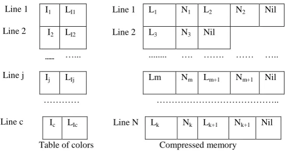
The table of the colors is a table of C lines and two columns (see figure 2). In each line; the first column contains an intensity of the pixel (binary values of the components R, G, B of the pixel) and the second a label, which is a binary code. The compressed memory contains the lists emitted by the line agents (see figure 2). The line N° I corresponds to the list of the line agent N° I. In this memory, instead of inserting the binary value of the components R, G, B which can be coded on 3 bytes for example, we insert the label of this intensity which is coded in little bits, followed by the number of repeats of this intensity.
-To create the line agents.
- To receive the tables emitted by the line agents.
- To prepare the compressed memory and the color table in the following way:
*With the reception of a table agent, the monitoring agent stores the relevant elements of this table in the compressed memory: For each intensity (the table is traversed in the direction growing of the columns); it seeksin the table of the colors if it exists. If so, the main agent stores the label associated with this intensity followed amongst its successive occurrences in the compressed memory at line corresponding of this agent. If this intensity does not exist in the table of the colors, the monitoring agent creates a new entry in this latter in which it stores code RGB of this intensity and a corresponding label.
- Each time a new entry is created, the monitoring agent sorts the table of colors in order to accelerate further research in this table.
- When a line agent sends a table and that the monitoring agent is occupied, this one is put in a queue.
- After treatment of a table by the monitoring agent, this one is destroyed.
- When an agent line finishes its course, it is destroyed by the monitoring agent.
- The algorithm stops when all the compressed memory is finished.
Line 1
Line 2
Line j
………… ………..
Line c
[image:5.595.137.424.304.454.2]Table of colors Compressed memory
Fig. 2 Table of colors and compressed memory I1 LI1 Line 1 L1 N1 L2 N2 Nil
I2 LI2 Line 2 L3 N3 Nil
... …... ... …. ……. …… …..
Ij LIj Lm Nm Lm+1 Nm+1 Nil
I I I
A A A
Image
Memory Columns 1-M
(N x M pixels)
Line 1 Line 2 Line N
Lines 1-N
I: Interaction between line agent and Monitoring Agent.
A: Memory access.
Fig. 3 Proposed systems
3-3
Algorithm for rebuilding of the image
In order to rebuild the original image, the algorithm, proceeds as follows:
- It reads the first value in compressed memory which is a color label, and then it read the repetition number of this color. The algorithm seeks in the color table for the pixel intensity and stores this pixel in the restoring memory at the first columns corresponding to the number of repetitions. After that, the algorithm seeks in the same way for the second value and its repetition number in the compressed memory and extracts the corresponding pixel from color table for rebuilding the next columns in restoring memory and so on.
- The algorithm stops when all the lists were treated.
4.
IMPLEMENTATION AND
EXPERIMENTAL RESULTS
For the design of our SMA application, we used the methodology AALAADIN [6]. The platform Madkit [8] which constitutes a powerful software tool for the development was used in the system implementation; this
configuration allows thousands of agents to work all independently in parallel.
MADKIT uses the Agent Group Rule (AGR) who an agent plays one or more roles in one or several groups, therefore we have designed two groups of agents: Monitoring group which concern the monitoring agent who it play rules consisting in the tasks it performs (such as creating color table, creating and destroying line agents, managing compressed memory ,…). The second group concerns the line agents and it is composed of the N agents who they play the rules such as: to seek for pixel intensities and theirs occurrences, to create agent table and to send it to monitoring agent, etc.
The information exchange between agents is vertically organized and concerns only monitoring agent and line agent. It is realized according to message passage allowed in MADKIT.
Figure 4 shows an example of application of our method in the compression of one 8x8 image. We obtain very satisfactory results and we reach very high compression ratios (in our example, the ration of lossless compression is near for 3.53).The ratio of compression is better for compression with
Monitoring Agent
Line Agent 1
Line Agent 2
Line Agent N
Table of colors
and
Compressed
Memory
Access
loss (Neglect the differences between nearby colors in the meme range for example).
Digital (8x8) image
Agent’s lists
A1 RGB(0,0,51) 3 RGB(0,0,19) 2 RGB(51,102,255) 3
A2 RGB(0,0,51) 1 RGB(51,102,255) 3 RGB(51,51,51) 4
A3 RGB(0,0,51) 1 RGB(51,204,255) 5 RGB(51,70,93) 2
A4 RGB(255,0,0) 8
A5 RGB(255,0,0) 6 RGB(0,255,0) 2
A6 RGB(0,0,255) 8
A7 RGB(0,0,255) 8
A8 RGB(0,0,0) 2 RGB(255,255,255) 4 RGB(0,0,0) 2
Table of colors
RGB(0,0,0) 0
RGB(0,0,19) 1
RGB(0,0,51) 2
RGB(0,0,255) 3
RGB(0,255,0) 4
RGB(51,51,51) 5
RGB(51,70,93) 6
RGB(51,102,255) 7
RGB(51,204,255) 8
RGB(255,0,0) 9
RGB(255,255,255) 10 Compressed memory
2 3 1 2 7 3
2 1 7 3 5 4
2 1 8 5 6 2
9 8
9 6 4 2
3 8
3 8
0 2 10 4 0 2
Fig. 4- Example of image compression
5- CONCLUSION
The obtained results are very satisfactory, and demonstrate the adaptation of our multi-agents system to the image compression domain.
The compression ratio which is equal to original image size divided by the compressed image size can be increased if we take into account the fact that when we are in a same range of color, tiny differences between these colors do not decrease the quality of the image. Then we can apply the following formula:
- Let C1(R1,G1,B1) pixel1 and C2 ( R2,G2,B2) color of the pixel2
d=√
- d: Distance between C1 and C2
- When d is lower or equal to ζ determined, we estimate that the two pixels C1 and C2 can be confused.
- This formula can be applied only when we are in a same range of color (example nuances of blue color).
We think of continuing this work by the realization of a multiprocessor system on chip (MPSOC) of compression of images where the agents will be represented by elementary processors DSP, as well as theextension of this application to other methods of compression (Fractal or by wavelet transforms)
6- BIBLIOGRAPHY
[1] Foley, J. D., Van Dam, A. and al. 1990 ‘Computer Graphics: Principles and Practice’. Addison-Welsey, Reading, MA, 2ndEdition.
[2] Jain, A. K. 1989. ‘Fundemantals of digital image coding’. Prentice Hall.
[3] Mac Kay, D. J. C. January 1995 ‘Information Theory, Inference and Learning Algorithms’ Cavendish Laboratory, Cambridge, Great Britain.
[4] Ferber, J. 1999. ‘Multi-Agent Systems. An Introduction to Distributed Artificial Intelligence’. Addison Wesley, London,
[5] Ferber, J. 1995 ‘Les systèmes multi-agents. Vers une intelligence collective’. InterEditions, Paris.(in french)
[6] Ferber, J. and Gutknecht, O. 1998 ‘Aalaadin: a meta-model for the analysis and design of organizations in multi-agent systems’, ICMAS 98 (International Conference on Multi-Agent Systems), Paris, Y. Demazeau (ed), IEEE Press, pp. 128-135.
[7] Ferber, J. and Gutknecht, O. 2000 ‘Operational Semantics of a Role-Based Agent Architecture (best paper award)’. Agent Theories, Architectures and Languages (ATAL 99), N. Jennings and Y. Lespérance Eds, Orlando, Springer-Verlag, LNAI, 1757, pp. 205-217.
[8] Gutknecht, O., Ferber, J. and Michel, F. 2000 ‘Madkit: une expérience d'architecture de plate-forme multi-agent générique. 8ème Journées Francophones sur l'Intelligence Artificielle Distribuée et les Systèmes Multi-Agents’ (JFIADSMA'2000), La Réunion, Hermès, pp. 223-236, (in French)
[9] Shannon, C. E. July and October 1948 ‘A mathematical theory of communication’ Bell System Technical Journal,vol. 27, pp. 379-423 and 623-656.
[11]Sayood, K. 2006 ‘Introduction to Data compression’ Morgan Kaufmann Series in Multimedia Information and Systems
[12]Golomb, S. 1966. ‘Run-length encoding’. IEEE Trans. Inform. Theory IT-12, pp. 399–401
[13]Nourani, N. and Tehranipour, M. H., January 2005 ‘RL-Huffman Encoding for Test Compressionand Power Reduction in Scan Applications’ ACM Transactions on Design Automation of Electronic Systems, Vol. 10, No. 1, pp. 91–115.
[14]Huffman , D. 1952. ‘A method for the construction of minimum redundancy codes’. In Proc. IRE,40, 9, 1098– 1101.
[15]Knieser, M., Wolff, F., Papachristou, C.,Weyer, D., and Mcintyre, D. 2003. ‘A technique for high ratio LZW compression’. In Proceedings of the Design, Automation and Test in Europe (DATE’03). Pp. 116–121.
[16]Pennebaker, W.B. and Mitchell J. L., 1993 ‘ JPEG: still image compression standard’. New York: Van Nostrand Reinhold.
[17]Wallace, G. K. April 1991 ‘The JPEG Still Picture Compression Standard’, Comm. ACM, vol. 34, no. 4, pp. 30-44.
[18]Buchsbaum, W. H. 1975 ‘Color TV Servicing’, third edition. Englewood Cliffs, NJ: Prentice Hall,. ISBN 0-13-152397-X
[19]Ahmed, N., Natarajan, T. and Rao, K. R. Jan. 1974 ‘Discrete Cosine Transform’, IEEE Trans. Computers, vol. C-23, pp 90-93
[20]Mandelbrot, B. 1977. ‘Fractals: form, chance and dimension’. San Francisco CA and Reading UK: W. H. Freeman & Co.
[21] Mandelbrot, B. 1985. ‘Fractals: Basic Concepts, Computation and Rendering’ . Notes for a course given in San Francisco CA on July 23, 1985 at SIGGRAPH 85. (Association for Computing Machinery; Special Interest Group on Computer Graphics.)
[22]Mandelbrot, B. 1982 ‘The fractal geometry of nature’. New York NY and Oxford UK: W. H. Freeman & Co.
[23]Barnsley, M. F. and Sloan, A. D., 1988 ‘A better way to compress images’, BYTE magazine, pp 215-223.
[24]Barnsley, M. F. 1988 ‘Fractal every where’, New-york: Academic Press, California.
[25]Davoine F., Antonini M., Chassery J. M. and Barland, M. 1996 ‘Fractal Image compression Based on Delaunay Triangulation and Vector Quantization’. IEEE Trans. image Processing, Vol.5, N° 2, pp 338-346.
[26]Duh, D. J., Jeng J. H. and Chen S.Y. 2005 ‘DCT based simple classification scheme for fractal image
compression’, Image and vision computing 23 , P. 1115-1121.
[27]Fisher, Y. 1995 ‘Fractal encoding with quadtree’ Chapter 3 in Fractal Image Compression: Theory and Applications to Digital Images’, Yuval Fisher, Ed, New York: Springer-Verlag, pp. 55-77.
[28]Fisher, Y. and Menlove, S., 1995 ‘Fractal encoding with HV partitions’, Chapter 6 in Fractal Image Compression: Theory and Applications to Digital Images, Yuval Fisher, Ed, New York: Springer-Verlag, pp. 119-136.
[29]Fisher, Y. 1995 ‘Fractal Image Compression : Theory and Application’, verlag, New York: Springer-Verlag, 1995, 341 P.
[30]Hassaballah, M., Makky, M. M. and Mahdy, B. Y. 2005 ‘A Fast Fractal Image Compression Method Based Entropy’ Electronic Letters on Computer Vision and Image Analysis 5(1): pp. 30-40.
[31]Stollnitz, E. J., DeRose, T. D. and Salesin D. H. May 1995 ‘Wavelets for computer graphics: A primer’, part 1. IEEE Computer Graphics and Applications,15(3):pp. 76–84.
[32]Talukder, K.H. and Harada, K., june 2006 ‘A Scheme of Wavelet Based Compression of 2D Image’, Proc. IMECS, Hong Kong, pp. 531-53.
[33]Talukder, K. H. , Koichi Harada, K. 2007 ‘ Haar Wavelet Based Approach for Image Compression and Quality Assessment of Compressed Image’ IAENG International Journal of Applied Mathematics, Volume 36, Issue 1.
[34]Devore, R., Jawerth, B. and Lucier, B. March 1992 ‘Image compression through wavelet transform coding’. IEEE Transactions on Information Theory, 38(2):719– 746.
[35]Marcellin, M. W., Gormish, M. J., Bilgin, A. and Boliek, M. P., March 2000 ‘An overview of JPEG-2000’ in Data Compression Conference Proceedings, pp. 523-541.
[36]Santa-Cruz, D., Grobois, R. and Elibrahimi, T., 2002 ‘JPEG 2000 performance evaluation and assessment’ Signal Processing: Image Communication 17 (2002) 113–130 elsevier.