APPLICATIONS
Systems for ...Automatic Control • Data editing and format revi-sion • Multiplexing data from several sources • Analog to digital co.nver-sion • Small digital com-puters • Complex data processing • Automatic checkout programing • Process control • Machine tool control • Weapons fire control • Digital data communication • Meteor burst data transmission • Nuclear energy analysis and instrumentation • Pulse height analysis
VERSATI LITV
MARKS TMI TYPE RB GENERAL PURPOSE MEMORIES with a wide range of applications for the computer design engineer who eyes costs, evaluates his time ... and expects high speed operation with long term reliability.Designed for use in data systems requiring small, fast memories compatib-le with logical control at rates to 200 kc.
Capacity - 128 to 1024 words - 4 to 24 bits per word - larger capacities with multiple units. 5-microsecond load or unload - 8-microsecond com plete memory cycle ..
Operating Modes - Sequential load and unload - random access load and unload - clear/write and read/restore memory cycles. Operations may be intermixed in any manner desired. Input and Output Signals - input may be either polarity and may be levels or pulses; output signals are levels.
Circle 1 on Reader Service Card.
TELEMETER MAGNETICS I n c
P. O. Box 329, Culver City, Californiaoffices and plant: 9937 Jefferson Blvd., Culver City, California
Ju,,, c •
I •
.
.
..
PIONEERS IN DEVELOPMENT AND ,MANUFACTURE OF CORE MEMORY PRODUCTS
.
• , • "!I' I
f . ... ., ,
r.
I
I
I \
\
\
,-Explorer VI
is
a
....
--
---;,;," "space laboratory
/"
orbiting
\
,
...
,
around
the
'''', earth
,
.... ....
...
--with
paddles
capturing'
sunlight
tor
power
---The scientific data that will some day enable us to probe successfully to the very fringes of the universe is being recorded and transmitted at this moment by the space laboratory Explorer VI, a satellite now in orbit around the earth. This project, carried out by Space Technology Laboratories for the National Aeronautics and Space Administration under the direction of the Air Forc~ Ballistic Missile Division, will advance man's knowledge of:
The earth and the solar system . .. The magnetic field strengths in space . .. The cosmic ray intensities away from earth . .. and,
The micrometeorite density encountered in inter-planetary travel. Explorer VI is the most sensitive and unique achievement ever launched into space. The 29" payload, STL designed and instrumented by STL in cooperation with the universities, will remain "vocal" for its anticipated one year life.
Space Technology
January/February 1960
--
...
--
-
--,
....
...
...
... ,
, ,
\
I I
/ \
\ I
I
How? Because Explorer VI's 132 pounds of electronic components are powered by storage batteries kept charged by the impingement of solar radiation on 8,000 cells in the four sails or paddles equivalent to 12.2 square feet in area • Many more of the scientific and technological miracles of Explorer VI win be reported to the world as it continues its epic' fligh t. The STL technical staff brings to this space research the same talents which have provided systems engineering and over-all direction since 1954 to the Air Force Missile Programs including Atlas, Thor, Titan, Minuteman, and the Pioneer I space probe.
Important staff positions in connection with these activities are now available for scientists and engineers with outstanding capabilities in propulsion, electronics, thermodynamics, aerodynamics, structures, astrophysics, computer technology, and other related fields and disciplines.
Inquiries and resumes
Laboratories, Inc.
invited. areP. O. Box 95004
2
100,000 ITERATIONS PER SECOND!
TRICE (Transistorized Realtime Incremental Computer, Expandable) is the first solid-state digital computer which combines the advantages of
analog and digital computers. Both linear and nonlinear differential equations are solved with realtime speed and digital accuracy.
ACCURACY: Maximum-One part in 67,000,000 ... variable, depending on speed required-for example, a 17 cps sine wave can be generated to an accuracy of 0.1 %., or, a 1. 7 cps sine wave can be generated· to an accuracy of 0.01 % .
SPEED: 100,OPO iterations per second for each inte-grator achieved by 3 mc clock frequency and com-pletely parallel operation.
RELIABILITY: Conservative solid-state design elim-inating moving parts provides the highest degree of reliability.
PROGRAMMING: Programmed with the ease of analog computers by use of a plugboard;
EXPANDABILlTY: Basic computer is expandable by addition of plug-in computing modules.
INPUT: Keyboard or punched paper tape
OUTPUT: Analog plotter or automatic typewriter TRICE computers are installed at major military centers. Applications of TRICE include: Control sys-tem stability, autopilot response, and pilot plant simu-lation; missile trajectory and satellite orbit parameter studies; impact prediction; realtime coordinate trans-formation; stable platform calculations; satellite orbit prediction; airborne guidance and control; studies in nuclear physics and reactor control.
""rite, outlining details of your proposed application, and the inquiry will be given personal attention by qualified computer engineers.
A SUBSIDIARY OF PACKARD BELL ELECTRONICS
1905 Armacost Avenue, Los Angeles 25, California • GRanite 8·4247 © 12·21·59 PB Circle 2 on Reader Service Card.
"
the automatic handling. of information
volume
6,
numberFRANK D. THOMPSON Publisher
GARDNER F. LANDON Vice President
SANTO A. LANZAROn A Editor
ETIENNE J. GUERIN European Editor
DR. HERB GROSCH Contributing Ed.
DONALD PRELL Technical Consultant
BETTE L. HOWE Production Manager
MARTHA KNOWLES Circulation Mgr.
LEO MONAHAN Art Director
DANIEL D. McCRACKEN C. L. W AN LASS
Editorial Advisers
RICHARD W. NIELSON Sales Mgr.
WARREN A. TIBBETTS
New England District Manager 434 Webster St., Manchester 4, N. H. NAtional 5-9498
RICHARD W. NIELSON
Eastern District Manager 141 E. 44th St., New York 17, N. Y. MUrray Hill 7-5180
ALBERT PUDV AN
Cleveland District Manager 3537 Lee Road, Shaker Heights 20, Ohio WAshington 1-9370
GILBERT THAYER
Midwest District Manager
ROBERT W. HEATH
Midwest Representative 201 N. Wells St., Chicago 6, III. Financial 6-1026
HAMILTON S. STYRON
Western District Manager
10373 W. Pi co Blvd., Los Angeles 64, Cal. BRadshaw 2-2643
E. J. GUERIN
European Manager Box 824
Stockholm 1, Sweden
Circulatian audited by Business Publications Audit
January/February 1960
IN THIS
ISSUE-FOUR NEW COMPUTERS
ARTICLES
8 The RW·400-A New Polymorphic Data System 17 McBee Has Another Small Machine
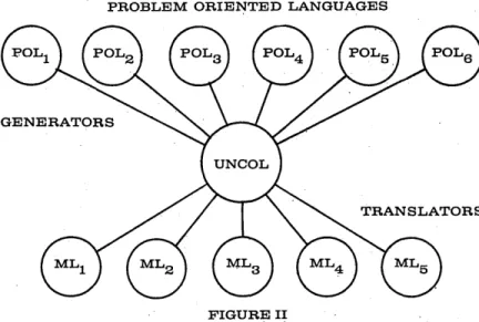
18 UNCaL, Universal Computer Oriented Language Revisited 23 EJCC Impressions
28 W JCC Plans Finalized
43 And Still More on Computer Conferences
48 Model 160 Makes Debut 54 COBOL is the Language!
55 The 7080, IBM's New Business System
DEPARTMENTS
26 People Moving Up in Datamation 29 Datamation News Briefs
32 Plus and Minus, by Herb Grosch 33 Datamation in Business and Science
37 New Products in Datamation 50 New Datamation Literature 56 Advertisers' Index
EDITORIAL OFFICES - 10373 W. PICO BLVD., LOS ANGELES 64, CALIF.
THIS ISSU E-27 ,000 COPI ES
DATAMATION is circulated without charge by name and title to the manufacturers and users of automatic, information-handling equipment In all branches of business, industry, government and military installations. Qualified Individuals in the United States and Canada are Invited to request this publication on their company letter-head, stating position and firm's business. Available to others by subscription at the rate of $5.00 annually; single Issue, $1.00 when available. No subscription agency Is authorized by us to solicit or take orders for subscriptions in the United States, Canada or overseas. DATAMATION will accept and consider articles dealing with small, medium and large electronic data processing systems; articles covering de-velopment and application of components,
sub-systems and sub-systems; and other general arti-cles of Interest to those In the data processing Industry. Material submitted should be accom-panied by pictures and Illustrations when pos-sible. Unsolicited manuscripts to be returned to writer should Include return postage but editor assumes rio responsibility for their safety (al-though all reasonable care will be taken). DATAMATION is published bl·monthly on or about the first day of every even-numbered month by F. D. Thompson Publications, Inc., Frank D. Thompson, president. Executive, Circulation and Advertising offices, 141 East 44th St., New York 17, N. Y. (MUrray Hill 7-5180). Editorial offices, 10373 West Plco Blvd., Los Angeles 64, Calif. (BRadshaw 2-0817). Published at Chi. cago illinois, application as controlled circula· tion publication pending at Waseca, Minn.
Copy-right 1960, F. D. Thompson Publications, Inc.
"We
are thousands
of
dollars
a,head
with our
Burroughs 205 computers ... "
ct • •• and keep a tight inventory control for our 1450
member-stores right down to the last pack of cigarettes shipped."
RANDOLPH PRICE, Controller, Certified Grocers of California, Ltd.
During a recent 13-week period, Certified Grocers provided more than 700-million smokes, cured (or tried to) about 5-million . headaches, dished up some 6-5-million cans of baby -food and kept a welter of household pets happy with around 12-million cans of dog and cat food. Little wonder, because Certified is the world's largest retailer-owned wholesale groc'ery distributor, and its member-store sales ~ank fourth among all of the nation's retail food distribution systems.
Randolph Price, Controller and Nick Walsh, Data Processing Manager
Certified Grocers was founded in 1922 by 15 visionary men who met in a quiet Pasadena hotel room to develop a group buying plan. They decided to pool their buying power in order to compete with the big chains. Their first purchase was a carload of soap, which they unloaded themselves at the rail-head. Their plan was successful, and by 1929 they purchased their own warehouse. Today, Certified's mem-bers own and operate more than 1450 stores in the West, and approximately 35 percent of the foodstuffs purchased in the greater Los Angeles area comes off the shelves of Certified member-stores.
Keeping an accurate tab on all that merchandise is a chore Certified has assigned to its two Burroughs 205 electronic ,data processing systems, purchased in 1956. One system controls the billing and inventory of a Los Angeles ware-house; the other handles the orders for goods shipped out of the San Fernando Valley warehouse and all non-food
orders. Between the two computing systems, they average some 200,000 items ordered daily. When frozen foods and delicatessen items are added to the computer program this month, the billing and stock control of over 18,000 different items will be automated.
"Reliable daily use is an extremely important factor in our application," reports Nick Walsh, Certified's Data Process-ing Manager, "because ours is a 7 -day per week, 20-hour per day, up-to-the-minute operation. Orders come in as checked off in a catalog. The orders, converted to punched cards, are merged with our stock status file on magnetic tape and entered into the computer. Our 205's process the orders, update. the magnetic tape file, and produce the punched cards from which invoices are prepared. The printed in-voices are then used to select merchandise from the ware-house and for the preparation of accounts receivable." Walsh continues, "We have found our 205's give us fast and accurate inventory control and save us money in the billing of daily invoices ... savings that are passed on to our mem-bers." "More than just smooth operating equipment is im-portant in a data processing installation," adds Controller Randolph Price. "A manufacturer must provide the training, service and over-all support such as Burroughs has given us ... this is essential to any successful EDP program."
Certified is also using its 205;s as an extremely valuable tool for another purpose: the preparation of purchase analy-sis reports. The reports, subscribed to by about 600 markets, give each member a current, accurate picture of all his pur-chases. They help him to decide which items are selling well, which to discontinue, shelf space to reserve, and of course, guide him in purchasing. The value of the reports is ex-pressed by one member, Mr. Ben Schwartz, Member of the Board of Directors and owner of Foods Co., who reports, "This is one of the finest services Certified offers. I receive as many as 8 or 9 different kinds of analysis reports over a period of time, at a cost which is negligible in comparison to their usefulness. These reports save me thousands of dollars!" Controller Price points out, "These special reports, made possible by our 205 computers, would have been impractic-able to prepare under our previous tub file and punched ,card system. Work that would have taken months now takes a few hours. The cost under our old system would have been' three to five times as much and the reports wouldn't have been available soon 'enough to do our members any good." The 205 systems are also being used for Certified's own complex purchasing operations. A periodic analysis keeps headquarters informed of the exact sales and distribution of thousands of items. Buyers are able to check out-of-stock situations quickly, determine the average inventory during the quarter, and accurately estimate average quarterly sales. Just as Burroughs 205's are helping Certified's manage-ment take costly guesswork out of many daily business de-cisions, so are hundreds of Burroughs electronic data proc-essing installations aiding other commercial and industrial users. Burroughs' complete line of computing systems is backed by a nationwide team of computer specialists. For additional information on how the 205 or other Burroughs electronic data processing equipment can help in your busi-ness, write ElectroData Division, Pasadena, California.
~
BurroughS Corporation
"NEW DIMENSIONS/in ekctTonics and data processing systems"Radar Tracking Computers
High Speed Repetitive
Display
MC-5900 Process Master Analog Computer
Some people can prove man and mouse are identical
MC-3302 Transistorized
Data Plotting Board
It's all according to the points of similarity you choose. Differences
are what really prove the superiority of man over mouse. Computers have differences, too. In fact, it's in these differences that the CSI-designed MC-5800 obsoletes every other Analog Computer. The best proof lies in
cold hard Specifications
• Exclusive dynamic memory makes automatic iterative solution of statistical or optimization problems a reality. . • Stable amplifier operation over the entire feed-back range from zero to infinity.
MC-5800 Precision Master Analog Computer
• Lowest amplifier grid-current <10-9 ampere. -.
I
• Amplifiers provide lowest noise level output-less than one milli-
-rv11(.,
I~
volt at unity gain.• Amplifier frequency response-flat to 10,000 cps and only 3 db
down at 28 kc. .
• Real-time precision @ speeds to 60 solutions/sec.
• Exclusive electronic generators of the function of two-or-more variables may be programmed at patch-board in same time required for setup of single-variable generators.
• Will program 134 amplifiers, 30 electronic multipliers, 18 diode function generators, 2 time-delay generators, 8 relay amplifiers, and 6 servos from one 2128-hole patchboard.
• Highest performance electronic multiplier-flat to 10,000 cps and only 3 db down at 20 kc.
• Dynamic memory
+
high-speed quick-reset rep-op provide practi. cal approach to solution of simultaneous partial differential equations. ill Dynamic memory with time-base accuracy of ±1O f,Lsec provides automatic parameter searching by iteration-an exclusive capability. • Solution of problems with up to 15 amplifiers in closed loops. • Plug-in dynamic components ease maintenance.• Lowest computer cross-talk-rejection greater than 2,000 to 1.
• Selection of real-time, expanded-time or high-speed compressed-time without reprogramming.
• Passive networks stabilized at
<
1 DC above room ambient-no oven required.• EVERY SPECIFICATION IS GUARANTEED TO BE TRUE PERFORMANCE STANDARD-IN SUSTAINED OPERATION.
• Only diode function generators utilizing resistors, potentiometers, and diodes of equal quality to those in computing networks. • Only diode function generators with individual hi-Io gain positions for each segment. .
• Lowest function generator drift
<
5 mv/8 hrs. • Lowest servo step-function overshoot-less than 1%. • DC tachometer feedback on all servos.• Complete control of all amplifiers, multipliers, dividers, and
non-linear equipment at patchboard. ",
• Exclusive equipment-door packaging for free access and quick maintenance without shutdown.
• Insulated patchboard prevents costly shorting accidents. • Power supplies eliminated from console-lowest, most stable operating temperatures-rise
<
3 DC.• Field expandable without mechanical rework or rewiring.
There are many more differences (over a hundred, in fact). Before you buy or lease your next analog computer, compare them all ... and we think you'll agree with us when we say: The MC-5800 obso-letes every other analog computer made.
Computer Systems, Inc.-designers and manufacturers of the
high-est precision analog computers and computer accessories.
---'~'-'
MC-701 Electronic
Multiplier Linear Programming Computer
-~
- : - - - .--~
---COMPUTER SYSTEMS, INC.,
611 BROADWAY. NEW YORK 12. N.Y •• SP 7-4016A Schlumberger Subsidiary jor·merly Mid-Century Instrumatic Corp.
Circle 4 on Reader Service Card.
1
2
3
4
5
6
7
8
9
10
11
12
13
14
15
16
17
18
19
DRTRMRTION
Solve
sorting bottlenecks
with an RCA 501
Up to 40% of your data processing dollar'can be
consumed in sorting. Now, RCA offers
a
major
breakthrough in sorting economy!
In speed, efficiency and low cost per item sorted, the RCA SOl
System is indeed impressive! Tape limited sorting operations are
greatly accelerated by the unique, combination of SOl features.
The RCA SOl can read and write simultaneously, on tape. To make
this possible, dual buffers-a pair for input 'and a pair for
output-are an integral feature of the system. Furthermore, the SOl can read
backward
avoiding time lost in rewinding.
Powerful features built into the tape system result in extremely
compact information recording (saving miles of tape and hours of
sorting time). True Variable Length Recording reads and writes items
in their natural length rather than in artificial fixed word and block
lengths. SOl Tape Units use an exceptionally short gap between items
and require only 3.S milliseconds to achieve full operating speed.
Superior sorting capabilities in the SOl are backed up by important
reliability features. Positive accuracy is afforded by Dual Recording
on tapes. All information is recorded in duplicate and both of the
side-by-side recordings have .individual parity checks.
If
either
character is faulty, the correct one is automatically used without
tape reread.
The sorting performance of the RCA 501 System is a fact of operating
experience-not theory or conjecture. For full information write
to-RADIO CORPORATION
01
AMERICA
Electronic Data Processing Division
CAMDEN 2, NEW JERSEY
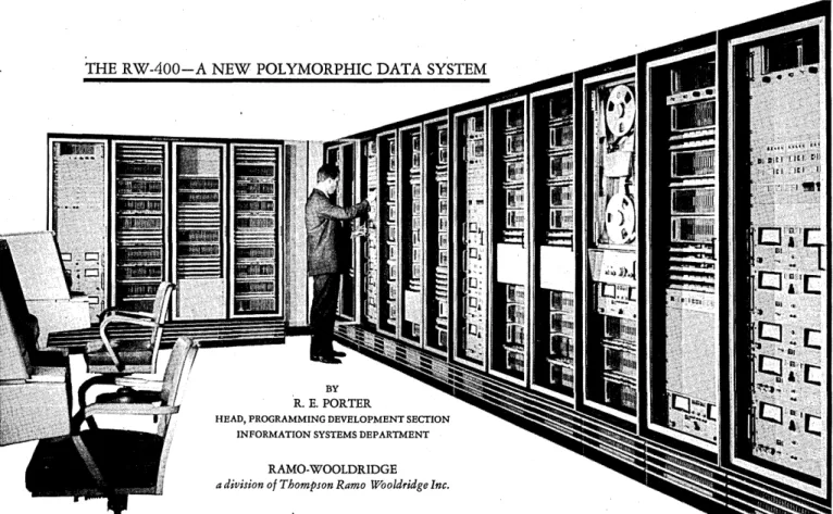
THE RW-400-A NEW POLYMORPHIC DATA SYSTEM
BY
'R. E. PORTER
HEAD, PROGRAMMING DEVELOPMENT SECTION INFORMATION SYSTEMS DEPARTMENT
RAMO-WOOLDRIDGE a division of Thompson Ramo Wooldridge Inc.
The RW -400 Data System is a new design concept. It was developed to meet the increasing demand for infor-mation processing equipment with adaptability, real-time reliability and power to cope with continuously-changing information handling requirements. It is a polymorphic system including a variety of functionally-independent modules. These are interconnect able through a program-controlled electronic switching center. Many pairs of modules may be independently connected, disconnected, and reconnected, in microseconds if need be, to meet con-tinuously-varying processing requirements. The system can assume whatever configuration is needed to handle problems of the moment.. Hence it is best characterized by the term "polymorphic" - having many shapes.
Rapid, program-controlled switching of many pairs of functionally-independent modules permits non disruptive system expandability, operating reliability, simultaneous multi-problem processing capability, and man-machine intercommunication feasibility. These are only, partially found in computers of conventional design.
Computer users have been forced heretofore to match problems to computer limitations. Problem changes posed serious reorientation and reprogramming difficulties. Changes from one computer to another model, due to growth in applications, often resulted· in large expendi-tures of time and money. During maintenance or mal-function of a conventional computer its entire processing capacity is shut down. Real time processing reliability cannot be maint&ined on an around-the-clock basis. The conventional machine must process its problems serially. This serious limitation is only partiaHy alleviated by time-sharing or computing-element-doubling designs. The high cost-per-hour of conventional computer operation rules out direct man-machine intercommunication during other than emergency situations.
8
The radically-new polymorphic design concept of the RW-400 Data System was evolved by Ramo-Wooldridge engineers to provide a practical solution to those informa-tion processing problems now inadequately handled by conventional computer designs. The RW -400 is a power-ful new tool in the field of intellectronics - the extension of man's intellect by electronics.
,system description
The RW -400 Data System contains an optional num-ber and variety of functionallypindependent modules. These communicate via a central electronic switching ex-change. Each module is designed, within practical eco-nomic and functional limits, to' maximize system adapta-bility over a wide range of problem types and sizes. This new design embodies the latest proven electronic design techniques, assuring high processing speeds and high equipment reliability. The RW-400's mocJularity assures reliable, round-the-clock processing of information with controllable computing capacity degradation during module maintenance or malfunction. Practical man-machine intercommunication is achieved in the RW -400 system by use of program-controlled information display and interrogation consoles.
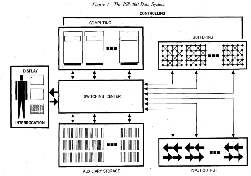
Figure 1 shows the over-all system design. Modules of various types communicate through a central exchange switching center. Computing and buffering modules provide control for the system. These modules are self-controlled and make possible completely -independent proce'ssing of two or more problems. One of the computer modules may be designated the master computer and in this role initiates and monitors actions of the entire system. An alert-inter-rupt network is provided to allow coordinated system action. Therefore, the system as applied to given informa-tion processing problems may change on a short range
DRTRMRTION·
(microsecond) basis, thus providing, through program-ming, a self-organizing aspect to the system. In addition; :the system may change through the years as the applica-tions change. The most efficient and economical comple-ment of equipcomple-ment is applied to the problem at all times.
An RW-400 system is built around an expandable Cen-tral Exchange (CX) to which a number of primary modules may be attached. These are: Computer Modules (CM); self-instructed Buffer Modules (BM); Magnetic Tape Modules (TM); Magnetic Drum Modules (DM); Peripheral Buffer Modules (PB); and console communica-tion Display Buffer Modules (DB). How many modules are put together in a system is entirely a function of sys-tem application. In addition to primary syssys-tem modules, . punched card, punched tape, high speed printing and control console devices are available. These handle nom-inal system' input/output requirements. Additional man-machine communication devices such as interrogation, dis- . play and .control conso'les, may be included in the system as problem requirements dictate. A Tape Adapter (TA) module is available to provide compatibility with mag-. netic tape of other computers. Information generated at Flexowriter inquiry and recording stations may be di-rectly received by the system via the· Peripheral Buffer Module. This latter module also buffers the receipt of , TWX and punched tape information.
The way in which a particular RW-400 Data System functions depends on the number and type of each module included. It may initially be composed of the minimum number .and variety of modules needed to do a small prob-lem or the initial. part of some large but yet-to-be-defined
problem. Such a system would work much like a conven-tional computer. It would probably include a buffer module and thus have a parallel data handling capability not found in the conventional design at a comparable price. The initial system installation may then be aug-mented by the timely addition of modules.
A buffer module (BM) has the capability to control its acquisition and dissemination of information independent-ly. The buffer provides a computer module with parallel data handling capability without complicating the prob-lem processing program with the conventional intermix-ture of arithmetic and housekeeping instructions. Infor-mation previously generated by the processing program may be appropriately disposed of within the system while processing continues. Data needed at a subsequent time in the processing may ~e retrieved from system storage in advance of need while processing progresses. The simul-taneity of these operations not only materially increases over-all processing speed but also increases the practical utility of the less costly types of internal system storage such as a magnetic tape.
The computer. (CM) or buffer (BM) modules, when act-ing in a controllact-ing capacity, may initiate connection to an information storage or handling module during that part of the processing program when the two can work profit-ably in unison. The pair of modules thus interconnected neither affect nor are affected by 9ther modules.' Logical interlocks prevent unwanted cross talk among modules. An intermodule communication system lets controlling modules signal status or alert other such modules of their need to communicate. The decision by a module receiving an alert
Figure 1 -T he R W ·400 Data System
CONTROLLING
I
COMPUTINGI
BUFFERING•••
DISPLAY
SWITCHING CENTER
INTERROGATION·
~
~
t
111111111111111111111111111111111 11111111111111111
11111111111111111111111111111111111
•••
11111111111111111H-~
\\
1111111111111111 Illl 1111 1111 1111 I 11111111111111111 '
~ ~
•
••
AUXILIARY STORAGE INPUT·OUTPUT
THE RW-400
TM
TM TA OM
TM OM
TM 1---- TA OM
-_
.. ,.-
- - " )..
...CM
I I
CM I ,\'I/
/ "
'"
... CMCM , /
,/
,1/
V
'I'
I /
I
1
II ,Ii.
/1'
--.
DB PR CD PB
DB PB
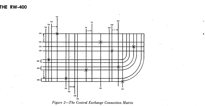
Figure 2-The Central Exchange Connection Matrix
signal to permit interruption or to proceed is optional with. that module. The optional interrupt feature is that needed to make the often-discussed but seldom-used
pro-gram interrupt capability both useful ~md practical. Pro-grams may thus permit inter~uptions only at convenient points in the processing sequence.
Modules may be assigned, under program control, to work together on a problem in proportion to its needs. As soon as a module's function is complete for a given prob-lem, that module may be released for reassignment to some other task. The system is thus self-controlled to match processing capacity to each pro hlem for the time necessary to do the job. Full system' capacity may be brought to bear upon a very large problem when needed. 1;'his, capacity 'may be apporlioned among a number of smaller problems' for simultaneous processing, program compilation, program checkout, module maintenance etc., when it is not needed for maximum system effort.
. From the preceding system desctiptiqn, it is apparent . that such ,equipment c:;m be expanded from a modest Initial installation into a very powerful and comprehen-sive information proces~ing center as requirement~ war-rant. More specific descriptions of principal system modules follow to give the ~eader a better feel for how this sys-tem might perform his information processing work.
the functional modules
The key to' appreciative understanding of the power of the RW-400 lies in k~owledgeof intermodule connection. It is appropriate to describe the Central Exqhange (CX) uri it first, then follow with descriptions of the various
modules. . '
the central exchange
The Central Exchange performs the vital function of in- . terconnecting a pair of modules whenever, requested to do so by either a computer or a buffer module. Since internal prbgr~mmed control is' only possible within a computer or a buffer· module, one of the interconnected pair of
10
modules must be either a computer or a buffer. The time in which any connection may be made or broken is about 65 microseconds. An exchange has basic capacity to con-nect any of 16 computer or buffer modules to any of 64 auxiliary function modules. There is nothing sacred about' the number 16 since it is possible to extend the CX
module's interconnection matrix through design modifica-tion when need arises. The CX is an expandable, program-controlled, elt~ctronic switching center capable of connect-ing or disconnectconnect-ing any available pair of modules in roughly the' time of one computer instruction execution. Figure 2 illustrates the permissible' module interconnec-tio:ns within the Central Exchange.
Every intersection on the illustration represents ,a pos-sible connection between modules. The "x-ed" intersec-tions indicate typical connecintersec-tions in force at any point in time. The control logic of the CX module's connection table ,prevents more than one interc~nnection on any horizontal (controlling) or vertical, (controlled) data path representation on the diagram. When connection is re-quested of the Central Exchange while orie of the required modules is already carrying out a previoUS assignment, the requesting II:lodule can be programmed to sense this con-dition and wait until connection can be made without in-terference. Should' waiting be undesirable,the requesting module can go on .about its business and check back later to see when the desired connection can 'be made. There is an implication here; of course, that knowing the kind of a' system. he is dealing with,. a programmer. requests
con-nec~idns in advance of need whenever possible.
Provision for 'master-slave control is included' via an Assignment Matrix e~tablisheci within the CX rriodule by ~ computer module previou'sly assigned to master status; Such a provisio~ is necessary to preclude inadvertent con-nection requests from' uncheckeq programs, or malfunc-tioning control modules from affecting sets of. modules simultaneously processing another problem. Connection re- . quests are therefore essentially filtered through both an
signment and an interconnection validity matrix prior to being' acted upon by the Central Exchange. The computer module manually assigned to master status is the only one permitted to cause the interconnection of a pair of modules which does not include itself.
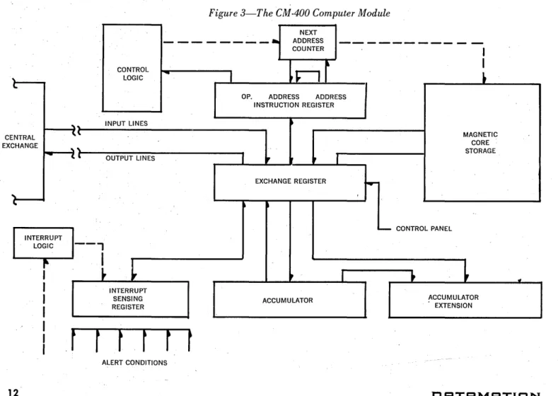
the computer module (See Figure 3, page 12J
The Computer Module (CM) is a self-sufficient, general purpose, two-address, parallel word, fixed point, random access computer. Its internal magnetic core memory has a capacity of 1024 words. A computer word consists of 26 information bits and 2 parity bits. Each parity bit is 'as-sociated with the 13-bit half word transferred in parallel via the Central Exchange to other system mod~les. The instruction repertoire of the CM consists of 38 primary instructions whose various modes effectively result in over 300 different operations. Of the 39 available CM-400 in-structions, 24 may be classified as "arithmetic" and 10 as "program control" or "sequence determining" instructions. Five additional instructions may be classified as "external" or "input/output" instructions. All but three of the 24 arithmetic instructions fit into a symmetric scheme of classification wherein there are seven basic operations, each having three distinct modes. The seven basic oper-ations are - add, subtract, absolute subtract, multiply, di-vide, square root and insert. The three modes are - Re-place, Hold, and Store. If we let the capital letter "G" identify the first operand, "H" identify the second oper-and, an "0" signify an arbitrary operation, the symbol "----." indicate replace, and "A" the word in the accum-ulator, then the three modes may be characterized as:
Replace: Hold: Store:
HOG ----. H, A HOG----'A A
°
G ----. H, AThe three remammg arithmetic operations are Add Ac-cumulate wherein the contents of Hand G are added to the Accumulator; Multiply Accumulate wherein the con-tents of H are multiplied by G and added to A; and Trans-mit where the contents of G are stored in H.
The ten program control instructions .are Store, Store Double Length Accumulator, Load Accumulator, Insert Mask in the S Register, Stop, Link Jump, Compare Jump, Tally Jump, Test Jump and a Multi-purpose Shift.
The five external instructions are those which cause data to be transmitted to or received from a device external to the computer. Each command is multi-purpose i,n nature and hence equivalent to several conventional external in-structions. The commands are - Command Output, Data Input, Conditional Data Input, Data Output and Char-acter Transfer. A comprehensive discussion of the varia-tion of each of these commands is not pertinent to this article. Suffice it to say that commands are available for carrying out a wide variety of intermodule data com-munication.
The interrupt capability of a Computer Module is a' logical generalization of the "trapping" feature found on several conventional computers. It permits the automatic interruption of a program, at the option of the program, ,when the computer module receives an "alert" that a con-dition requiring attention has arisen. It can be used to warn the program when an error of some type has oc-curred, minimize unproductive computer waiting time while another module completes its task, eliminate many' programmed status test instructions and provide a
con-January/February 1960
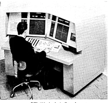
RW-400 Analysis Console
venient means of subjecting one computer module to the control of another. Program control of interruptions with-in a CM-400 is accomplished through the sense register S. This register may be filled with an interrupt mask by means of the Insert S instruction. A bit by bit correspond-ence exists between the S register and the interrupt regis-ter and the inregis-terrupt regisregis-ter I to which the alert lines are connected. A Test Jump instruction can be used to examine the coincidence between these registers of an alert signal in a bit position corresponding to a one in' the S register mask. If an alert is received by the computer during the execution of an instruction, control will be transferred to memory location "0" at the end of the
in-st~uction if, and only if, (a) the sense bit corresponding to
the alert is a "one," (b) the master sense bit is a "one," and (c) the instruction was not an "Insert S." The master sense bit in the S ,register may be programmed to permit the interrupt to take place according to the interrupt mask or to inhibit interrupt until the program can conveniently cope with it. All instructions being executed at the time an interrupt condition occurs are completed before the in-terruption is allowed to take place.
Figure 3 schematically illustrates the Computer Mod-ule's primary registers and the interconnecting informa-tion paths.
Typical two-address addition and subtraction times are approximately 35 microseconds including memory access time. Multiplication takes about 80 microseconds, and di-vision and square root about 130 and 170 microseconds respectively.
Before attempting to draw a comparison between a CM and a deluxe conventional computer the reader should bear in mind the trade offs in featmes versus cost; paral-lel processing versus sequential processing; independent information handling versus program complicating "house-keeping"; and real time system reliability versus periodic inoperability. The only valid comparison is that between the RW-400 Data System and a conventional computer applied to the same task. The contribution to the RW-400 system made by the Buffer Modules can be better assessed by the reader after the following description has been considered.
THE RW-400
the buffer module
A Buffer Module consists of 'two independent logical buffer units, each having 1024 words of random access magnetic core storage and a number of internal. registers used in performing its functions when in the self-control-ling mode. A Buffer Module may be connected t~ a Com-puter Module so that the Buffer's core storage is 'access-ible to the computer as an extension of the compute~'s own storage .. A Buffer may also serve as an intermediary device between a computer and another module, such as a tape or drum, 'to minimize time conventionally lost in data transfers. The Buffer is capable of recognizing and executing certain instructions stored in its own memory.
It can therefore be leff to perform data handling functions on 'its own while computer modules are otherwise oc-,cupied.
A Buffer Module may be connected to a Computer Module and t~e buffer 1024 word storage used as an in- , directly addressed extension of the computer's own work-ing storage. When the address 1023 (all ones) appears in the operand field of a computer instruction to be executed, the computer is signalled that the operand refers to some cell in buffer storage. The computer then uses the num-ber in the buffer read register R (or in the case of a few instructions, the buffer write register W) as the effective address designated by the operand field of the instruction. Extended addressing; may be used in either the first or second operand field of the instruction or in both operand
fields. If extended addressing is used in only one operand field, the effective address designated by that field is the number in register R. A "I" is automatically added to the contents of the R register after the instruction is executed.
If extended addressing is used in both operand fields of an instruction, the effective address of the' first operand is the number in register R and the effective address of the sec-ond operand is one more than, the number in register R. A "2" is automatically added to the contents of register R after the execution of. this type of. instruction. The R (or W) register may be preset to any desired initial con-dition by means of the computer's Command Output in-struction. All the commands 'being executed by the com-puter must be stored within the comcom-puter module's storage and may not be in buffer cells addressed by the computer at execution time. The extended addressing and buffer register indexing may be used to materially simplify re-petitive data acquisition operations.
The primary function of a Buffer Module. is not, how-ever, that of an auxiliary computer storage unit. The drum and tape modules more aptly :serve this function in'the RW-400 system. A Buffer Module is capable of operating autonomously and of controlling other modules such as Tape Modules, Drum Modules, Peripheral Buffers, Dis-play Buffers, Printers or Plotters. This capability enables the Buffer Modules in a system to perform routine tape searching and data transferral tasks thereby freeing the Computer Modules to do more computing. In its "self-instruction" mode, the buffer executes its own internally stored program in much the same fashion as a computer. The memory of a Buffer Module will therefore be oc-cupied by its own control programs as well as blocks of data which it is holding for transmission to other units.
Figure 3-The CM·400 Computer Module
CENTRAL EXCHANGE
12
INTERRUPT LOGIC
NEXT
- - - -
ADDRESS-COUNTER
I
CONTROL
nJ
I
LOGIC
-
I
~OP. ADDRESS ADDRESS
INSTRUCTION REGISTER
"
(\. INPUT LINES ~ MAGNETICCORE
,
,
STORAGEOUTPUT LINES
,
•
,
EXCHANGE REGISTER
...
~
- CONTROL PANEL
--,
l
~
~I
.~~
~
INTERRUPT
SENSING ACCUMULATOR ACCUMULATOR
REGISTER EXTENSION
,r
r
t
r
r r
ALERT CONDITIONS
IlRTRMRTION
I'
The buffer is used to acquire information from the 'rela-tively slower auxiliary storage and communication modules while the computer proceeds at high speed. Blocl,<s of in-formation retrieved in advance of computer need by the buffer may then be rapidly transferred to the computer's own storage or operated upon as they stand in the buffer via the indirect addressing capability of the computer. An-other·feature of the buffer is its switching capability. Each Buffer Module is composed of two buffer units tied to-gether. A unit function switching feature permits the em-ployment of the two units together in an alternating mode of operation. Continuous information transfer from tape to computer, for example, may be accomplished without stopping the tape unit. A switching instruction executed simultaneously by both units of a buffer module causes whatever devices were connected to the first unit to be connected to the second and vice versa. '
Now that the functional controlling modules and the module interconnection concept have been discussed, the more conventional auxiliary storage modules available with the' syst,em may be described to round out the proc-essing capabmty of the system.
the tape modules
A tape Module consists of an altered Ampex FR-300 tape transport plus the necessary power supplies and con· trol circliitry to effect information reading. writing and control. One inch mylar tape is used. Information is writ· ten on 16 channels - two of which are clock channels. The remaining 14 channels consist of 13 information bits plus. parity. The information reading or recording rate is 15,000 computer words per.second. Data may be recorded on tape in variable blocks up to a maximum of 1024 words per block (the size of the storage available to hold the data in a sending or receiving module). Each block is preceded by a block identification which perrrtits selective tape information searching by a Buffer Module. Single blocks iinbedded in' a tape file of other blocks can be overwritten. A two-stack head permits automatic verifica-tion of each block as it is written. Re~dback parity errors are automatically detected during the writing process. Thus dropout ·areas may be detenTIin~d while the data is still available in a computer or buffer for recording else· where.
A description of the RW-400's tape handling capability would not be complete without mentioning the Tape Adapter (TA) module. This is a self-contained unit capable of performing the reading and writing of magnetic tapes in a format acceptable to the IBM 704 and 709 systems. . The T A consists of an Ampex FR-300 half-inch digital tape transport, including dual gap head and servo control system; reading, writing and control circuits; and a module housing with its own blower and power supply.
the drum module
The Drum Module (DM) contains a magnetic drum with storage capacity of 8192 words. It may be connected to either a Computer or a Buffer Module through the Cen-tral Exchange. Average access time to the first word posi-tion on the drum is 8% milliseconds. Successive words are transmitted at the rate of 60,000 computer words per sec-ond. The Drum Module is conventionally used as an inter.· mediate item storage device to minimize tape handling time.
special system communication modules
The external dl~.ta and man-machine communication of'
January/February 1960
RW-400 Buffer Module
the RW-400 Data System are handled via drum buffer modules. A wide variety of asynchronously operated equip-ment is speed matched and program controlled through the features designed into these special system communi-cation modules.
The Peripheral Buffer (PB) provides input/output buff-ers for communication between Computer or Buffer Modules and relatively slow speed ~xternal devices such as Flexowriters, Plotters, Punched Tape Handlers, Tele-type Lines and Keyboard Operated Equipment. The Peripheral Buffer stores its information in four pairs of bands which operate alternately as circulating registers. Each band contains eight input and eight' output buffers for a total of 32 input buffers and 32 output buffers in each Peripheral Buffer Module. Each buffer is a drum band sector 64 computer words long: Conventionally one input' and one output buffer sector are connected to each external device (such as a Flexowriter) to permit two-way communication between the external device and the RW-400 system .
the display buffer
A Display Buffer (DB) acts as a recirculating storage for the cathode ray tube display units in' a Display Con-sole. Information to be displayed is sent to the DB band associated with a particular display tube via the Central Exchange. The Display Buffer sends only status informa-tion back to other system modules upon request. The in-formation displayed on any tube is. controlled· by the bit pattern sent to the Display Buffer. The display pattern is regenerated 30 times per second to minimiz~ image fading and flicker. The preceding explanation of the Display Buff-er has little meaning to a readBuff-er unfamiliar with the fea-tures of the Display Console itself. This console is there-fore described in ~ore detail in the following paragraphs.
display consoles
Display Consoles can give a problem «analyst" or «monitor" a visual picture of the status or results of any
THE RW-400
information being handled by the RW-400 system. In ad-dition to the actual Cathode Ray Tube, numerical indica-tor, signal lamp and typewriter information outputs,' several types of keyboard activated system control and parameter entry facilities are provided on the console. The total man-machine communication facility represented by each console is designed to be primariiy ' a function of the computer control programs initiated by the analyst via his console.
A set of Display Control Keys generate messages which are recorded on a, Peripheral Buffer sector for later inter-pretation and display generation by a computer program. A set of Process Step Keys are provided the analyst so that he can initiate preprogrammed system processing variations. Associated with the Process Step Keys is an overlay or "program card" which permits the assignment of a variety of meanings to, the set of Process Step Keys. Insertion of the overlay by,the analyst gives him a unique label for each Process Step Key and automatically cues the controlling computer to assign the corresponding set of programs to each key message. A Data Entry Keyboard is pTovided on the console so that the analyst can enter control parameters when asked to do so via the display devices.
A Joystick Lever affords the console operator a means of controlling the position of cross hair markers on the cathode ray display tubes. Associated with the joystick are control keys which may be used to send a message to the controlling computer specifying the coordinates of the cross hairs. Control programs may be written, for example, , to act upon this information to reorient the display with
respect to the area selected by the cross hair position. A Light Gun is also provided as a means of selecting any point on the cathode ray tube displays. The gun emits a small beam of light. With the beam centered on a
gi~en
point on the cathode ray display tube, pressing the trigger results in the auto~atic generation of a message to the Peripheral Buffer specifying the address in the Dis-play Buffer containing the coordinates of the selectedpoint. , ,
A set of Status and Error lights are contained on the Display Console to provide the console operator with over-all knowledge of the system and thus minimize con-flicting control requests- and intermodule interference. For example, ,a P,eripheral Buffer may, not be ready to accept a console key message until after certain previously re-quested control actions have been completed. The Status Lights indicate this condition to the console operator so that he may act accordingly.
the printer module . "
The Printer Module (PR) is basically
a
160 column, 900 line per minute Anelex type printer. It receives information from either a Computer or a Buffer module via the Cen-tral Exchange. Individual characters to be printed are represented by a 6-bit code and are transmitted four to a computer word. Zero suppression, line completion and in-formation block end codes are included for format con-trol. A plugboard is provided for flexibility in columnar data arrangement. Paper feed is controlled by means' of a'14
loop of 7 -channel punched paper tape. Control of the printing operation has been arranged so that the con-nected control module may send line headings from one set of memory locations, stop sending information while going to
a
different part of the memory, and then proceed to send data from this new set of memory locations to complete a' line of print.the punched card modules
The RW-400 Data System may be equipped with a high speed punched card reading module (CR) and ,an IBM card punch. The CR communicates with Computer or Buffer modules via the Central Exchange. It is capable of reading 80, column, punched cards at the rate of 2500 cards per minute. The card punch is connected to the sys-tem through the Peripheral Buffer Module (PB) since it is a relatively low speed device. Emphasis has not been placed on directly connected punched card equipment since the sources of large volumes of punched cards usually convert this data into magnetic, tape form which may be more rapidly handled using, the Tape Adapter Module (TA).
summary
The RW-400 Data System, based upon modularly con-structed, independently operating and flexibly connected components, is the logically evolved successor to conven-tional computer designs. It provides the means by which information processing requirements can be" met with equipment capable of producing timely results at a cost commensurate with problem economic value. System o~
solescence is minimized by the expandability in numbers and types of processing modules. Real time reliability is assured by component duplication at minimum cost and by the advanced design techniques employed in the sys-tem's manufacture. Man-machine communication facilities are program controlled for maximum flexibility. Parallel processing and parallel information handling modules in-crease the system's speed and adaptability when handling complex computing workloads. This polymorphic design truly represents an extension of man's intellect through
electronics. •
i',
Randall Porter supervises the Programming De-velopment Section of the Information Systems De-, partment within Ramo-Wooldridge., This section develops advanced com-puter programming tech" niques in support of RW-400 computing systems. Porter was formerly Ap-plied Mathematics Staff Engineer .Jor the Boeing AirplaneConipanyin Seaule,W ashington. He managed the computer processing work ofihe Telecomputing Corporation during its formative years. He was employed by, t~e
Lockheed A it-craft Corporation during the war years arid 'participated in the structural engineering de-sign and analysis of the Constellation and Constitu-tion airplanes: He is an honor graduate and former instructor at the Curtiss-Wright Technical Institute of Aeronautics. His mechanized computation experi-ence spans the period, from 1942 to the present. '
Save
$4,840
a month
with the Stromberg-Carlson S-C
4020
high-speed computer readout
MICROFILM
Here's a typical example of how the Stromberg-Carlson S-C 4020 high-speed microfilm printer can save as nlUch as $4,840 a month. Assume that an average of 2,100 graphs with 375 points each are required each month. Twenty-five engineering aids can do this work by hand at an estimated cost of $8,800 a month .. One S-C 4020 high-speed printer can do the same work for $3,960 ... a saving of $4,840.
High-speed graph plotting is just one of the ways the S-C 4020 can save you
time and money. It is ideal for all kinds of high-speed computer printing, filing and archive storage. It will record on microfilm at the rate of 15,000 plotting points or alphanumeric cha~acters a sec-ond - either on-line or off-line. The unique CHARACTRON® shaped beam tube assures top quality reproduction of both tabular and graphic material. Selected data, either tabular or graphic, may be projected on an acces-sory viewing screen only 8 seconds after film exposure. The projection unit
STROIVIBERG-CARLSON'"
I
is useful for monitoring computers. The S-C 4020 has been proven reli-able in actual service at such installa-tions as the U.S. Navy's David Taylor Model Basin, Carderock, Md. Printers are in production right now. You can have your own printer saving hundreds of valuable engineering· man-hours within six months.
LITERATURE AVAILABLE Write to Dept. A-28, Stromberg-Carlson-San Diego, 1895 Hancock Street, San Diego 12, .California.
A DIVISION OF
GENERAL DVNAIVIIC5 CORPORATION
Circle 6 on Reader Service Card.
16
Maybe you've been one of these unfortunates . . . who've spent thousands of dollars ... plus many man hours ... to record valu-able information on magnetic tapes ... only to find· the data '4seless from accidental distortion or erasure.
'Unexpected exposure to an unpredicted magnetic field, and presto! -your valuable data is filled with irritating odd noises. Dis-tortions may result in virtual data erasure.
Unprepared tape users never realize the danger of loss until
it's too late. ' ,
Such losses have bec9me increasingly common from damaging magnetic fields during transportation or storage. These fields may be produced by airplane radar or generating equipment or other power accessories. Also by' generators, power lines, power supplies, motors, transformers, welding machines, magnetic tables on surface grinders, magnetic chucks, degaussers, solenoids, etc.
Since 1956, many military and commercial tape users success-fully avoid such unpleasant surprises. Their solution is shipping and storing valuable tapes in sturdy NETIC Tape Data Preservers. Data remains clear, distinct and distortion-free in NETIC Pre-servers. Original recorded fidelity is permanently maintained.
Don't take chances with your valuable magnetic tapes. Keep
them permanently clear and distinct for every year of their useful life
in dependable NETIC Preservers. Can be supplied in virtually any size and shape to your requirement. Write for further details today.
For complete, distortion - free protection of valuable tapes during transportation or storage. Single or multiple containers available in many convenient sizes or shapes.
MAGNETIC SHIELD DIVISION PERFECTION MICA CO.
1322 No. Elston Avenue, Chicago 22, IllinoisOriginators of Permanenlly Effective Netic Co-Netic Magnetic Shielding
Circle 7 on Reader Service Card.
:DRTRMRTION
4
•
MCBEE HAS ANOTHER SMALL MACHINE
rpc-4000 joins company's 19p-30
An article comparing desk-size computers ("Speaking of Small Computers," DATAMATION,November/Decem-ber, 1959) was barely in the hands of our readers when it became slightly outdated. This was brought about by the announcement of two new small machines (see below and page 48)' and the knowledge that perhaps one more is being made ready for marketing quite soon.
Royal McBee's LGP-30 was one of the entrants in the above-mentioned survey and but for that firm's ability to keep the machine described below a secret and a matter of a few days in terms of an official machine announce-ment, McB would have had two computers in the lineup.
Royal McBee's RPC-4000 is by any standards an im-pressive small machine. While DATAMATION does not intend to expose it to a comparison at this time (we will wait a few months in hopes that we will be able to place eight machines in review) a summatio"n of its outstanding features is offered first.
The first thing one notes when reviewing the 4000' s specs is that its drum memory has an 8,008-word capacity, approximately twice that offered by any competitor. A lock-in feature (see text below) must be called novel, new and unique.
The 4000 has good speed, probably not the fastest of the desk-size machines, but still good. It will boast 42 commands. Optional high-speed input-output units will be available and seventeen I/O devices can be used on-line. The machine has one index register, a repeat command, an eight-word accumulator and a ten-amp drain (can be plugged into any standard outlet). The 4000 is transis-torized and will be available in Tuly of this year. Monthly
rental will be $1,750; total sales price - $87,500.
Some details: R McB states that the magnetiC dIllm memory unit is encased in
a:
metal shroud to protect it from dust particles or accidental damage. The drum is tapered and floats on a cushion of air. When the machineJanuary/Feb ruary .1960
is idle, the drum rests away from the heads. Air pressure automatically raises the drum to correct operating posi-tion when power is turned on. Physical size has been kept down by the use of miniaturized heads The memory has a storage capacity of 8,008 words (word length is 32 usable bits, accommodating a nine-decimal digit number).
A variety of programs' can be stored permanently for access when needed. A venige access time to the main storage is 8.5 milliseconds. Memory may be searched for full or partial words (through a masking feature) at a rate of nearly 200,000 words per minute. Three thousand words of memory can be scanned in less than one second for full or partial equality to
a
.key word or full or partial equality or superiority to a key word. Part of memory (136 words) is available through the high-speed line or dual access tracks in from 1 to 6 milliseconds.The main memory is non-volatile. Switches allow in-formation to be locked in the main memory in increments of 1024 words - so that it cannot be altered by program or operator error. The arithmetic and control section of memory includes three one-word reg-isters, and one «one-or-eight" word register. When used in conjunction with the repeat execution feature, the «one-or-eight" word register provides for block arithmetic and block transfers without special commands. Up to seventeen input-output devices (60 minor modifications) may be connected to the 4000, on-line.
Standard input-output equipment for the machine is a tape typewriter system complete with typewriter, desk, tape punch-read console and chair, .. all specially designed as . a unit. Basic reader speed is 60 characters per second, basic punch speed is 30 charaoters per second. A reversible photo-electric reader ($15,300 or $300 per month (which reads punched paper tape at 500 characters per second, and a .high-speed punch ($20,400 or $400 per month) which operates at 300 characters per second, are available as op-tional accessories for system expansion .. All of the paper' tape equipment includes full tape handling reel facilities. .
Peripheral equipment to be made available in 1961 includes a magnetic tape drum and a line printer. The tape drum will have a maxi-mum storage capacity of about 200,000 com-puter words per replaceable tape car,tridge. Lower capacity tapes - with resultant faster ac-cess times --,- may" be used if. desired. Peripheral input-output equipment may be turned on and off automatically by the computer, however, a comprehensive manual control system permits full operator control. Six branch point switches are provided. Other switches permit manual selection of peripheral equipment and a variety of input modes. Stand-ard equipment provides compatibility with existing paper tape systems. A Universal Translator, to be available later, will further extend compatibility.
Circle 101 on' ReadE7r Service Card.