DESIGN AND ANALYSIS OF HIGHWAY WIND POWER GENERATION
USING VERTICAL AXIS WIND TURBINE
Manikanda Gokul A
1, Krishna M
1, Venkadesh B
1, Kalyani. S
2,
Karuppasamy. A
31
Dept of Electrical and Electronics Engineering, Kamaraj College of Engg and Technology, Tamil Nadu, India
2Professor, Dept of Electrical and Electronics Engineering, Kamaraj College of Engg and Technology,
Tamil Nadu, India
3
Asst Professor, Dept of Electrical and Electronics Engineering, Kamaraj College of Engg and Technology, Tamil
Nadu, India
---***---
Abstract - Energy is an important aspect in our every day’slife. The resources we use are limited where as the population consuming the same is increasing day by day. Nowaday the requirement of electricity is much higher than its generation, hence the main the objective of our work is to produce electricity in low cost with no effect on environment. The objective of the work is to design a wind turbine to recapture wind energy from vehicles on the highway. A considerable amount of wind energy is produced due to the pressure difference created by the moving vehicles on the highways. This wind energy can be utilized for the generation of electrical energy with the help of vertical axis wind turbines. This work aims to extract this energy in the most efficient manner. Vertical axis wind turbine can be installed on the median of the roads so that the wind from both sides of the median will act tangentially in opposite direction on both sides of the turbine thereby increasing effective wind speed acting on the turbine. This wind flow will depend on the velocity of the vehicle, size of the vehicle and intensity of the traffic. Based on the studies made an optimal wind turbine design has to be made. The wind power harnessed through this method can be used for street lighting, traffic signal lighting, toll gates etc.
Key Words: Renewable Energy, Vertical Axis Wind
Turbine, Wind Power.
1. INTRODUCTION
Wind energy is the fastest growing source of clean energy worldwide. A major issue with the technology is fluctuation in the source of wind. There is a near constant source of wind power on the highways due to rapidly moving vehicles. The motivation for this project is to contribute to the global trend towards clean energy in a feasible way. Most wind turbines in use today are conventional wind mills with three airfoil shaped blades arraigned around a horizontal axis. These turbines must be turned to face into the wind and in general require significant air velocities to operate. Another style of turbine is one where the blades are positioned vertically or transverse to the axis of rotation. These turbines will always rotate in the same direction regardless of the fluid flow. Due to the independence from the direction of the fluid flow, these turbines have found applications in tidal and surface current flows. To see how effective this sort of
turbine would be in air, a helical turbine based on the designs and patents of Dr. Alexander M. Gorlov was chosen. His turbine was developed to improve upon the design of Georges J. M. Darrius by increasing the efficiency and removing pulsating stresses on the blades, caused by the blades hitting their aerodynamic stall in the course of rotation, which often resulted in fatigue failure in the blades or the joints that secured them to the shaft. The turbine takes the Darrius type turbine, which has a plurality of blades arranged transverse to the axis of rotation, and adds a helical twist to their path, insuring that regardless of the position of the turbine, a portion of the blade is always positioned in the position that gives maximum lift. This feature reduces the pulsations that are common in a Darrius type turbine. In his investigations, Gorlov claims that his turbine is significantly more efficient than Darrius’ and has achieved overall efficiencies between 30% and 35%. For this investigation, a helical turbine was tested inside and outside a wind tunnel using an electric generator (inside tests only) and a torque meter paired with a tachometer to measure the output power of the turbine and calculate its efficiency. In the end, the turbine did not come close to the claimed 30% efficiency, reaching at best an efficiency of around 0.35%. Further investigations should be made to determine why the results from this investigation were as low as they are.
2. LITERATURE SURVEY
A combined type straight-bladed vertical axis wind turbine (CT -SBV A WT) was designed in this study by setting a Savonius rotor having good starting performance into the SB-VA WT Savonius rotor set in the SB-V A WT can greatly improve the starting performance of the SB-V A WT.
Madani, Cosic, Sadarangani, “A Permanent Magnet Synchronous Generator for a Small Scale Vertical Axis Wind Turbine”,[4], states that A design of surface mounted permanent magnet synchronous generator with concentrated windings. The design features low harmonic contents in the air gap flux density and in the induced voltage. Chongyang Zhao, “Experiment Validation of Vertical Axis Wind Turbine Control System based on Wind Energy Utilization Coefficient Characteristics”, [5], states that Wind generator external characteristics are measured. Speed ratio and wind turbine characteristics are analyzed.
3. OBJECTIVES AND SCOPE
The main objective is to harvest and recapture the maximum amount of wind energy from the automobiles running on the highways. The unused and considerable amount of wind is used to drive the vertical wind turbine, which will use the kinetic energy of the wind to produce the electrical energy. Increased turbulence levels yield greater fluctuations in wind speed and direction. Unlike traditional horizontal axis wind turbine (HAWT), vertical axis wind turbine effectively captures turbulent winds which are typical in urban settings. An effort is made to create a vertical axis wind mill of 50W capacity. Our aim is to design the turbine which will capture the maximum of wind in any direction by placing it at optimum place and height by considering both the cost and safety of the system. This system can be used in huge number to generate the huge amount of useful electrical energy. This energy can be stored and transferred to nearest rural places where we can fulfill the demand of electricity. The thought of design directs us to look into the various aspects such as manufacturing, noise, cost which leads us to our additional aim of analyzing the system to overcome the usual technical glitches. The project brief involves the design of a small scale wind turbine that can be easily mass produced and fitted on every highway medians to aid electricity consumption.
The design should provide the following;
Be able to generate a non-trivial electricity supply to the streetlights when operating. Excess electricity can be fed back into the national grid or charge secondary batteries.
The scale of the turbine should be within the limits of the Indian highways.
Designed to operate at suitable wind speeds typical to India weather in highways areas.
Possess a fail-safe system as a consequence of an over-speed event.
This report will mainly focus on the computational modelling development on a Vertical axis wind turbine while providing a detailed understanding of the advantages and disadvantages of using a model based design method, which focuses on computer simulation to predict the performance of the turbine before attempting to fabricate the turbine.
4. VERTICAL AXIS WIND TURBINE
However, recent concerns about fossil fuel depletion as well as greenhouse gas emissions have brought increasing interest in wind power. Modern wind turbines operate under the same principles as historic windmills. They convert the momentum of the wind into kinetic energy of rotating blades, which is then channeled into a rotating shaft. Within this general definition, there are two subgroups: horizontal axis wind turbines (HAWT) and vertical axis wind turbines (VAWTs).
The main reason behind developing Vertical Axis Wind turbines is that they work regardless of the wind direction. VAWTs do not require a yaw mechanism and are very fixed in the sense that no change to their direction or that of the blade is made once installed. The lack of a yaw mechanism is one of the reasons VAWTs are not as expensive or complicated to make. This makes them ideal for small-scale applications such as remote areas with very small electric load. Their blades do not require a mechanism to change their angle as they work with any wind direction. VAWTs are considerably less noisy than HAWTs, which makes them more socially accepted. In addition to this, the small size means they can be integrated easily within an urban setting, and present no danger to the wildlife in rural areas.
They still share many components with HAWTs however, such as the shaft, the gearbox, the tower, and the generator unit. The placement of these units is different, since in VAWTs the gearbox and generator are placed at the base of the unit and do not require as much support as HAWTs. This means easier access for maintenance and repairs, which lowers the overall cost of such systems.
As mentioned before, the way the Betz limit is derived uses some assumptions that are not applicable to VAWTs. However, in general VAWTs are far less efficient than HAWTs.
the wind is high. High wind turbulence, wind fluctuations, and high directional variability can cause significant problems for a HAWT, whereas VAWTs can operate well”.
Fig 1. Vertical Axis Wind Turbine
5. DESIGN
Blades of the wind turbines are classified in two categories;
• Drag type
• Lift type
5.1 DRAG TYPE
In reference to the tower, if the rotor is downwind, the wind turbine is called drag type or downwind type. The drag adjusts its motion, according to the frontal area of an object if it were facing the wind. Designing an object that travels at a fast pace through fluids is an efficient idea. This theory helps to explain the reason why the construction of cars, submarines and bicycle helmets are built in a long shape.
Drag type machines consist of an advantage in which they may have been constructed without the use of a yaw mechanism. This occurs when both the nacelle and the rotor consist of an appropriate design that makes it follow the wind. In addition, a very important benefit of this rotor is that it is made to be flexible. This advantage applies to how much the machine weighs, as well as the structural dynamics. In order to lighten the load of the tower, the blades are designed to bend at higher wind speeds. In other words, the most important benefit of this downwind machine is that it is built using less weight in comparison to lift type machines.
5.2 LIFT TYPE
Lift type also known as upwind type, is when the rotor of the wind turbine is facing the wind. Being able to avoid the wind shade from behind the tower is the greatest benefit that has been acknowledged for the lift type design. Majority of wind turbine designers prefer to use this exact design. The wind begins to bend in a direction away from the tower, without even reaching the tower. This behavior
occurs even though the tower is round and smooth. Thus, there is a slim drop in the amount of wind power every single time the rotor is passing the tower. However, like any other design, the lift type has a downside. This weakness of the lift type design is that the rotor is required to be manufactured to be inflexible and must be distanced from the tower. A yaw mechanism is required within a lift type machine is order to ensure that the rotor is facing the wind. Looking at the common principles that are found in airplanes, kites and birds, manufacturers of the lift blade design aim for the same properties. The blade is primarily an airfoil or is considered a wing. Various wind speeds and differences in pressure are created between the top and bottom blade surfaces, when the air flows right past the blade. When the pressure is interacted with the lower surface blade, the pressure is much greater, therefore, behaves as to lift the blade. Lift is turned into rotational motion when the blades are joined to the central axis, acting as the wind turbine rotor. When dealing with electricity generation, wind turbines are a better option as they are powered by lift, resulting in acquiring greater rotational speeds in comparison to drag types.
5.3 MECHANICAL DESIGN
There are four various types of blades which have been utilized in conducting the experiments. The four types of blades are as follows; (a) curved blade, (b) straight blade, (c) aerofoil blade and finally (d) Twisted blade. These four blades are demonstrated in Fig.2 it is evident to be aware that a few investigations conducted on straight and curved blades have currently been carried out.
Fig. 2
TABLE 1 MECHANICAL DESIGN DETAILS
S.NO PARTICULARS SPECIFICATIONS
1 Radius 0.45m
2 Height 0.9m
3 Gear Ratio 1:10
4 Weight 12Kg(Approx)
5 Angle 120 degree
5.4 ANALYSIS OF DIFFERENT BLADES
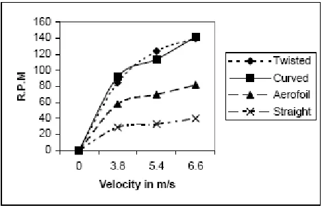
In reference to air velocities, when testing the ranges, the straight blade has been discovered to have less efficiency in comparison to other blades as shown in the figure below. The reason for this is because there is a balanced quantity of drag force acting on both blades, as they are placed 120° apart while dealing with the same quantity of air stream.
Fig 3
The turbine has three blades at an angle of 120º to each other. Such design of the blades so that can harness maximum wind energy striking it. The blades are one piece structure folder in the form of an arc, having a curvature less that of a semi-circle. Curved type of design doesn’t need much effort to get accelerated compared to other stated designs. Owing to the fact that, GI steel sheet has a long list of advantages like good tensile and compressive strength, rugged and comparative long life, high stiffness to weight ratio, good resistance against corrosion, it is employed for the formation of blades. Glass fiber reinforced plastic (GRP) would have been the ideal choice for the blades but this would become too expensive and hence nullified the objective of producing a low cost wind turbine. The dimensions of the blades are dependent on the width of the road divider and considering it chosen the dimension of the blades as 100×50 cm².The cross-arms are Y-shaped steel roads which are square in cross-section. The wind turbine’s center is the connecting section between the blades leading to the main shaft. Each blade is connected to the hub with the help of three steel rods. These rods are welded to the hub as well as bolted to the
blades. The length of the cross arm is 80cm. We have used mild steel for the hub. This is used in order to make the structure stable. The hub is joined to the main shaft. Solid M.S. rod is used to make the main shaft. In addition, the main shaft is made to pass thought two bearings. The two bearings are supposed with the help of a bearing house placed top and bottom of the blade. The generator is rested on wooden base, which is kept on the ground. By keeping it on the ground the center of gravity of the entire system is lowered.
6. ANALYSIS OF TURBINE OUTPUT 6.1 TURBINE OUTPUT
Fig 4
Fig 5 0
10 20 30
Vo
ltage
(V)
Speed (m/s)
Voltage Output(V) vs
Speed (m/s)
Voltage Output(V)
0 10 20 30 40 50
31
.52
25
.64
15
.12
16
.46
22
.11
42
.43
40
.48
To
rq
u
e
(N
-m)
Velocity (RPM)
Torque(N-m) vs Velocity
(RPM)
[image:4.596.44.279.328.483.2]Table 2 Turbine Output Speed vs Torque Output
6.2 CONVERTER CIRCUIT
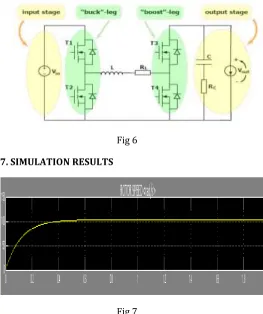
DC-DC power converters are employed in order to transform an unregulated DC voltage input (i.e. a voltage that possibly contains disturbances) in a regulated output voltage. For example, a DC-DC power converter can transform an unregulated (i.e. distorted) 9V input voltage in a regulated (i.e.”clean”) voltage of 12V at the output. Some DC-DC power converters have a fixed output reference and ensure that such voltage is always delivered, no matter what the input is; some others can have a variable output reference, which can be therefore set depending on the current need of the device the power converter is used in. The converter discussed in this Work belongs to this second category. In particular, the converter is able to deliver output voltages both higher as well as lower than (or even equal to) the input voltage; this is why it is referred to as a”buck-boost” (or”step-up/step-down”) power converter.
The three basic switching power supply topologies in common use are the buck, boost, and buck-boost. These topologies are nonisolated, i.e., the input and output voltages share a common ground. There are, however, isolated derivations of these nonisolated topologies.
The power supply topology refers to how the switches, output inductor, and output capacitor are connected. Each topology has unique properties. These properties include the steady-state voltage conversion ratios, the nature of the input and output currents, and the character of the output voltage ripple. Another important property is the frequency response of the duty-cycle-to-output-voltage transfer function.
The buck-boost is a popular nonisolated, inverting power stage topology, sometimes called a step-up/down power stage. Power supply designers choose the buck-boost power stage because the output voltage is inverted from the input voltage, and the output voltage can be either higher or lower than the input voltage. The topology gets its name from producing an output voltage that can be higher (like a boost power stage) or lower (like a buck power stage) in magnitude than the input voltage. However, the output voltage is opposite in polarity from the input voltage. The input current for a buck-boost power stage is discontinuous or pulsating due to the power switch (Q1) current that pulses from zero to IL every switching cycle. The output current for a buck-boost power stage is also discontinuous or pulsating. This is because the output diode only conducts during a portion of the switching cycle. The output capacitor supplies the entire load current for the rest of the switching cycle.
Fig 6
7. SIMULATION RESULTS
Fig 7 S.No Torque Output(N-m) Velocity
(rpm)
1 31.52 21.82
2 29.81 23.08
3 25.64 26.82
4 18.12 37.95
5 15.12 45.49
6 16.97 40.53
7 16.46 41.79
8 18.74 36.7
9 22.11 31.11
10 27.57 24.95
11 42.43 16.21
12 38.04 18.08
13 40.48 16.99
Fig 8
8. BLOCK DIAGRAM
Fig 9
8.1 Operation of Hardware
This vertical axis highway windmill is placed in the highway dividers. When the air is forced by passing the vehicle from both sides the speed of a wind at the center place is higher than the pedestrian walking lane. This wind make the VAHW to rotate at high speed and it is coupled to generator to produce electricity and the power can be stored in the battery and it is utilized at the night time. This energy conversion process is explained by several following steps:
Step-1: In the first step the forced wind and middle part of the highway will hit wind turbine blades and make a rotation in it The wind turbine blade will rotate at clockwise direction even when the vehicle move in any of the side of the highway. Because the arrangement of the wind turbine blades are in that manner.
Step-2: The vertical axis highway windmill the wind blade
turbine is coupled with the two generators .one is in the top and the other one is at the bottom of the wind turbine blades. When the turbine blade rotates the coupled generators will produce electricity in both directions.
Step-3: Thus the mechanical energy is converted into electrical energy by using dc generator and this produced power is stored in the battery and is utilized by application wise.
8.2 Explanation
8.2.1 VERTICAL AXIS WIND TURBINE 8.2.1.1 Blade Design
Wind turbine blades have on aerofoil type cross section and a variable pitch. While designing the size of blade it is must to know the weight and cost of blades. The ideal wind generator has an infinite number of infinitely thin blades. In the real world, more blades give more torque, but slower speed, and most alternators need fairly good speed to cut in. 2 bladed designs are very fast (and therefore perform very well) and easy to build, but can suffer from a chattering phenomenon while yawing due to imbalanced forces on the blades. 3 bladed designs are very common and are usually a very good choice, but are harder to build than 2- bladed designs .Going to more than 4 blades results in many complications, such as material strength problems with very thin blades. Even one-bladed designs with a counterweight are possible.
This number defines how much faster than the wind speed the tips of your blades are designed to travel. Your blades will perform best at this speed, but will actually work well over a range of speeds. The ideal tip speed ratio depends on rotor diameter, blade width, blade pitch, RPM needed by the alternator, and wind speed. Higher TSRs are better for alternators and generators that require high rpm but the wind speed characteristics at your particular site will make a big difference also. If in doubt, start in the middle and change your blade design depending on measured performance.
8.2.1.2 Centre Shaft
The shaft of the turbine consists of a single 1.5m length of steel measuring 25mm in diameter. The use of steel over a lighter metal such as cast iron was based on the availability of materials. The top and bottom ends mild steel of length 1inch each are respectively are fixed to give strength to the hollow shaft. A solid shaft rotating at 75 rpm is assumed to be made of mild steel.
8.2.1.3 Bearing
2.54cm. Bearings are generally provided for supporting the shaft and smooth operation of shaft.
8.2.2 DC Generator
An electrical generator is a machine which converts mechanical energy (or power) into electrical energy (or power). Induced e.m.f is produced in it according to Faraday's law of electromagnetic induction.
This e.m.f cause a current to flow if the conductor circuit is closed.
Hence, two basic essential parts of an electrical generator are:
a) Magnetic field.
b) Conductor or conductors which can move as to cut the flux.
Generators are driven by a source of mechanical power, which is usually called the prime mover of the generator(steam turbine, diesel engine, or even an electric motor).
8.2.2.1 Permanent-magnet field DC Generator
Permanent-magnet DC machines are widely found in a wide variety of low-power applications. The field winding is replaced by a permanent magnet, resulting in simpler construction. Chief among these is that they do not require external excitation and its associated power dissipation to
magnetic fields in the machine the space required for the
permanent magnets may be less than that required for the field winding, and thus machine may be smaller, and in some cases cheaper, than their externally excited counter parts. Notice that the rotor of this machines consists of a conventional DC armature with commutator segments and brushes.
8.2.3 LED Strip Light
A LED strip light is a flexible circuit board populated by Surface mounted light emitting diodes and other components that usually comes with an adhesive backing. Traditionally, Strip lights had been used solely in accent lighting, back lighting, task lighting and decorative lighting applications.
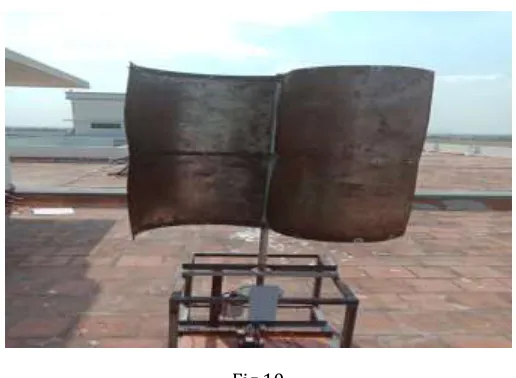
9. HARDWARE
Fig 10
[image:7.596.303.561.101.290.2]10. RESULTS AND DISCUSSION
Table 3 Output Parameters
11. CONCLUSION AND FUTURE SCOPE
The main aim of this project is to build a small scale Vertical Axis Wind Turbine to generate power. These turbines are easier to construct and less investment is needed. The implementation of vertical axis wind turbine on road dividers, on side of train tracks and power supply for isolated area would be a great asset to the ministry of Non-conventional energy Resources as it would reduce the burden on the consumption of conventional energy sources. They can be installed on any highway with the width being the only constraint. Since, turbine size is small, it can harness a limited amount of wind. Therefore they can be used for street lighting on any busy road and light up the
S.No Voltage
Output(V) Output(N-m) Torque Velocity (rpm)
1 14.3 31.52 21.82
2 17.4 29.81 23.08
3 21.3 25.64 26.82
4 24.3 18.12 37.95
5 28.2 15.12 45.49
6 25.4 16.97 40.53
7 26.7 16.46 41.79
8 23.6 18.74 36.7
9 22.8 22.11 31.11
10 19.2 27.57 24.95
11 11.3 42.43 16.21
12 11.7 38.04 18.08
13 12.3 40.48 16.99
advertisement hoardings. Furthermore, these turbines can find application in lighting up commercial buildings. Other application could be in diversions on highways, traffic lights, industrial buildings, simply in household neighborhoods.
Since the battery is portable we can use it in some other location for any low voltage purpose. Thus there is balance between the cost and the power available. The emerging trends in the technology have shown a way to the use of non-conventional energy sources so Efficiently and a little effort at the side may find an effective solution for the boom of the electrical energy by the society.
In order to properly design a generator there are many components that are required to be studied such as wind speed, power, current, voltage and many more. In order to calculate the important generator parameters, MATLAB script file was developed using all necessary equations. Additional constraints such as efficiency, copper and iron losses. This resulted in Successful design calculations.
Successful calculation led us to implementation of this design. MATLAB Simulink Software was used to make this VAWT simulation model. All the calculated values were Implemented and observed the output. It was significant to modify a few values to improve Output voltage and current waveforms were analyzed and compared with calculated Values.
The next step is to test each blade experimentally, both to validate the previous models as well as determine conclusively whether the new blade increases output power.
12. REFERENCES
1. Chongyang Zhao,Jun Luo, "Experiment Validation of Vertical AxisWind Turbine Control System based on Wind Energy Utilization Coefficient Characteristics, IEEE June 2010.
2. Aravind, Rajparthiban, Rajprasad, “Mathematical Toolbox and its application in the Development of Laboratory Scale Vertical Axis Wind Turbine”, IEEE Dec 2012.
3. Yan Li, Fang Feng, “Computer Simulation on the Performance of a Combined-type Vertical Axis wind Turbine”, IEEE Mar 2010
4. Madani, Cosic, Sadarangani, “A Permanent Magnet Synchronous Generator for a Small Scale Vertical Axis Wind Turbine” (ICCDA 2011).
5. Chongyang Zhao, “Experiment Validation of Vertical Axis Wind Turbine Control System based on Wind Energy UtilizationCoefficient Characteristics”, IEEE, Mar 2015.
6. Cooper, P. and Kennedy, O. “ Development and Analysis of a Novel Vertical Axis Wind Turbine” university of Wollongong, 2004
7. Golding, E. and Harris, R. “The Generation of Electricity by Wind Power” E. & F. Spon Ltd, London, 1976
8. H. Polinder, J. A. Ferreira, B. B. Jensen, A. B. Abrahamsen, K. Atallah, and R. A. McMahon,“Trends in wind turbine generator systems,” IEEE J. Emerg. Sel. Topics Power Electron., vol.1, no. 3, pp. 174–185,Sep. 2013.
9. Omijih,B.O., Nmom,C.S. and Nlewem,E. “Modeling of a Vertical Axis Wind Turbine with Permanent magnet synchronous Generator for Nigeria” Electrical/Electronic Engineering, University of Port Harcourt, Nigeria, February 2013
BIOGRAPHIEES
Manikanda Gokul.A Final year Student at Kamaraj college of Engineering and Technology. Areas of Interest: High Voltage
Krishna.M Final Year Student at Kamaraj college of Engineering and Technology, Madurai. Areas of Interest: Electrical Machines
Kalyani.S Doctrate, Professor and Head Of Department of Electrical and Electronics Engineering at Kamaraj College of Engineering and Technolgy, Madurai. Guide for our work.