http://wrap.warwick.ac.uk
Original citation:
McNamee, Joshua, Hatchett, Jonathan, Debattista, Kurt and Chalmers, Alan (2015) Live
HDR video streaming on commodity hardware. In: SPIE Optics + Photonics, San Diego,
9-13 Aug 2015. Published in: SPIE Proceedings : Applications of Digital Image
Processing XXXVIII, 9599 95990U
Permanent WRAP url:
http://wrap.warwick.ac.uk/74414
Copyright and reuse:
The Warwick Research Archive Portal (WRAP) makes this work by researchers of the
University of Warwick available open access under the following conditions. Copyright ©
and all moral rights to the version of the paper presented here belong to the individual
author(s) and/or other copyright owners. To the extent reasonable and practicable the
material made available in WRAP has been checked for eligibility before being made
available.
Copies of full items can be used for personal research or study, educational, or not-for
profit purposes without prior permission or charge. Provided that the authors, title and
full bibliographic details are credited, a hyperlink and/or URL is given for the original
metadata page and the content is not changed in any way.
Publisher’s statement:
Citation
: McNamee, Joshua, Hatchett, Jonathan, Debattista, Kurt and Chalmers, Alan,
“Live HDR video streaming on commodity hardware” SPIE Proceedings : Applications of
Digital Image Processing XXXVIII, 9599, (2015).
Copyright notice
: Copyright 2015 Society of Photo-Optical Instrumentation Engineers.
One print or electronic copy may be made for personal use only. Systematic
reproduction and distribution, duplication of any material in this paper for a fee or for
commercial purposes, or modification of the content of the paper are prohibited.
DOI abstract link
:
http://dx.doi.org/10.1117/12.2187457
A note on versions:
The version presented here may differ from the published version or, version of record, if
you wish to cite this item you are advised to consult the publisher’s version. Please see
the ‘permanent WRAP url’ above for details on accessing the published version and note
that access may require a subscription.
Live HDR Video Streaming on Commodity Hardware
Joshua McNamee
a,b, Jonathan Hatchett
a,b, Kurt Debattista
a,b, and Alan Chalmers
a,b,
a
University of Warwick, Coventry, UK
bgoHDR Ltd.
ABSTRACT
High Dynamic Range (HDR) video provides a step change in viewing experience, for example the ability to clearly see the soccer ball when it is kicked from the shadow of the stadium into sunshine. To achieve the full potential of HDR video, so-called true HDR, it is crucial that all the dynamic range that was captured is delivered to the display device and tone mapping is only confined to the display. Furthermore, to ensure widespread uptake of HDR imaging, it should be low cost and available on commodity hardware. This paper describes an end-to-end HDR pipeline for capturing, encoding and streaming high-definition HDR video in real-time using off-the-shelf components. All the lighting that is captured by HDR-enabled consumer cameras is delivered via the pipeline to any display, including HDR displays and even mobile devices with minimum latency. The system thus provides an integrated HDR video pipeline that includes everything from capture to post-production, archival and storage, compression, transmission, and display.
Keywords: high dynamic range, HDR video, commodity hardware, end-to-end HDR pipeline, video streaming
1. INTRODUCTION
High dynamic range (HDR) imaging allows the full range of lighting in a real world scene to be captured, stored, transmitted and displayed. In imaging, dynamic range is the ratio between the brightest and darkest regions of detail captured within a single image. It is typically measured in logarithmic unitsstops, which represent doublings of light intensity. Traditional imaging systems, so called Low Dynamic Range (LDR), also known as Standard Dynamic Range (SDR), can capture and display about 8 stops. The Human Visual System through eye adaption can perceive detail in scenes ranging from starlight to bright sunshine, and in a single scene about 20 stops (with minimum adaption).
While LDR imaging systems use 8 bits of information to store the luminance and each of the chrominance channels, HDR requires floating point numbers to represent the full range of light in a scene. With 32 bits required per colour channel, i.e. 96 bits per pixel, a single High Definition (1920×1080) HDR frame requires 24 Mbytes. At a frame rate of 30 fps, a minute of HDR video results in 42 GBytes of data, compared to just 9 GBytes for a minute of LDR data. Efficient data formats and compression techniques are thus essential in order to cope with the large data requirements of HDR data on existing infrastructures. Several pixel formats have been proposed to represent HDR pixel values, including shared exponent RGBE encoding used in the Radiance image format1and LogLuv encoding used in a custom HDR version of the TIFF images.2 They are not, however,
sufficiently efficient to be adopted as a standard for HDR pixel representation. Currently, the most widely used file format for individual HDR frames is OpenEXR.
(a) (b) (c) (d)
[image:2.595.68.551.573.661.2]Developed for the movie industry, OpenEXR has been released as free software under a modified BSD license, with the most recent release appearing in August 2014.3 OpenEXR is not, however, suitable for the representation of HDR video as sequences must be stored as discrete frames - without any form of inter-frame compression.
A number of consumer camera systems already claim to provide HDR video, such as the mobile phone cameras in the Sony Xperia series and the Samsung Galaxy S6. While these cameras may capture a wider dynamic range, the data is only available as tone mapped LDR footage. Tone mapping is a means of attempting to preserve the perceived contrast in a scene within the constraints of an LDR infrastructure. A wide variety of tone mapping operators (TMOs) have been proposed (see Banterle et. al (2011)4). The majority of these have been for static images, but more recently a number of TMOs for HDR video have been proposed which take into account potential temporal artefacts.5, 6 When it comes to displays, most are currently LDR, although a
commercial HDR display, the SIM2 HDR47ES6MB, capable of displaying a peak luminance of 6,000 cd/m2 is
available.7 Where the dynamic range of the display matches that of the delivered lighting, the images can be
displayed in a straightforward manner.8 If this is not the case then the images can be simply clipped to the lower
dynamic range, or preferably tone mapped to provide an enhanced viewing experience on the traditional display.
This paper describes an end-to-end HDR video pipeline. The full range of light in a scene, captured by an HDR-enabled consumer camera, is delivered across the pipeline where it can be directly displayed on an HDR display, such as the SIM2, or tone mapped for display on a traditional LDR monitor, including mobile devices. In addition, because the full range of light captured is preserved for every pixel along the entire pipeline to the display (so called true-HDR), it is possible to modulate the exposure of each individual pixel, either automatically or by the user, to show detail in the scene that might otherwise not be visible. The viewer can adopt an active attitude, engaging with the video to dynamically alter the exposure of the entire scene, or a window within the scene. For example, as Figure 1 shows, the user is able to choose the exposure around the goal area to be able to see the goal as it scored, even when this is in bright “sunshine”.
While HDR pipelines have previously been described,9 and shown at events such as IBC 2011 and IBC 2013
and NAB 2013-2015 by goHDR and also at NAB 2015 by other companies such as Dolby, the goal of the system presented in this paper is to provide HDR video on commodity devices at HD resolution and at a frame-rate comparable with that of commercial LDR systems. In addition, this HDR pipeline is the first to incorporate real-time compression and streaming.
2. THE HDR VIDEO END-TO-END PIPELINE
Consumers are continuously demanding improved realism and quality of captured and displayed images. HDR imaging captures and delivers the actual light present in a real world scene. By faithfully representing the wide range of intensities that are present in the scene (indeed, potentially more than the human eye can see), HDR imaging isscene-referred rather thandisplay-referred, encompassing in theory all future imaging systems intended for the human eye.
2.1 Capture
Well known techniques of HDR imaging use multiple exposures with different exposure times to create a static HDR image.10 This static approach fails when objects move causing ghosting artefacts. To minimise artefacts
and still capture a large dynamic range, dedicated HDR video systems use, for example, multiple sensors with the same integration time through a single lens.11, 12
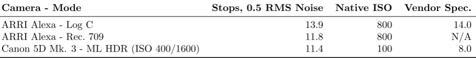
Camera - Mode Stops, 0.5 RMS Noise Native ISO Vendor Spec.
ARRI Alexa - Log C 13.9 800 14.0
ARRI Alexa - Rec. 709 11.8 800 N/A
[image:4.595.72.543.73.131.2]Canon 5D Mk. 3 - ML HDR (ISO 400/1600) 11.4 100 8.0
Table 1: Evaluation of HDR video systems.
2.2 Manipulation
Manipulation includes applications such as colour grading, post production, image-based lighting and scene analysis. We can distinguish between off-line processes for cinematographic or pre-recorded TV content and real-time processes for live transmissions. Off-line processes are done in general by using commercial editing tools such as Da Vinci Resolve from BlackMagic, The Foundry’s Nuke, etc. For real-time HDR video manipulation, there are GPU based solutions that offer half-float, single-float or 16-bit integer data manipulation resources. OpenCV includes GPU functions while Halide14provides a novel approach as a functional language that targets
different compilers including CUDA and OpenCL. VicomTech showcased its first prototype for live HDR video manipulation, named Tebas, in the Futures Park section of the NAB 2014 exhibition. In this system, the captured material was captured and pre-processed by goHDR’s Flare HDR video system. It was then processed and mixed by Tebas before finally being displayed on a SIM2 monitor.15
2.3 Encoding, storage and transmission
As discussed above, a key problem with HDR video systems is the amount of data that is generated. Efficient data formats and compression techniques are thus essential in order to cope with the large data requirements of HDR video data on existing infrastructures. Reducing the volume of digital data benefits areas including, but not limited to: a reduction of transmission channel bandwidth; a decrease of the buffering and storage requirement; and a reduction of data-transmission time at a given rate.
HDR video compression may be classified as one-stream or two-stream.16 The one-stream approach utilises a
single layer transfer function to map the HDR content to a fixed number of bits, typically 10 to 12.17–21 While it
is true that many scenes do contain a dynamic range of lighting that is sufficiently low to be adequately contained within a limited number of bits, there are many others for which 10 or even 12 bits may be insufficient.16
In a two-stream method the encoder has one input HDR video and two bit streams as an output.22–25 These
streams can consist of (1) a standard compliant bit stream, for example HEVC Main 10, H.264 etc. and (2) one another stream corresponding to additional data to reconstruct HDR video (which can also consist of a standard bit stream) or metadata (if so desired). When combined these streams reproduce the full HDR content with minimal (or indeed no) perceptual loss.
2.4 Display
The company Brightside pioneered the first HDR displays based on two technologies: a digital light processing (DLP) projector, and light emitting diodes (LEDs).8 The brightness of the Brightside DR37-P prototype HDR
display was subsequently characterised using a spectroradiometer to record spectral radiance, chromaticities and luminance.26 From this data the true increase in gamut of the display due to the additional LED layer was
estimated. The colour space of the HDR displays have similar chromaticities to any other 8-bit per channel device, so there is no increased chromaticity resolution, but it is in the luminance dimension where the colour space is perceived to increase resulting in 35,961,042 potential colours compared to the 16,777,216 of a typical LCD display.
In early 2015, Samsung announced their TV model UN65JS9500 that can reach a peak luminance of 1,000 cd/m2,
however this is still some way in terms of dynamic range from the commercial HDR displays currently sold by SIM2 which are currently capable of up to 6,000 cd/m2. SIM2’s unique monitor comprises an HD resolution (1920×1080) LCD panel. The high brightness is obtained by an array of powerful white LEDs which replace the
3. COMMODITY HDR VIDEO
To ensure the wide embrace of HDR video, it has to be affordable and thus available for “every-day” use.
3.1 HDR-enabled consumer cameras
Magic Lantern (ML) is free software that improves the functionality of a range of Canon DSLR cameras.27
In particular, ML provides a firmware patch which was capable of alternating the ISO exposure setting of a Canon 5D Mark III on a frame-by-frame basis. We adapted this firmware to perform the alternating exposures in real-time over the camera’s HDMI interface. A Blackmagic capture card was used to input the stream of alternating exposures into a computer where a GPU based HDR merging algorithm combined the alternating exposures into single HDR frames. Deghosting methods, such as Ram´ırez Orozco et. al and Granados et. al (2013),28, 29 are necessary to minimise any ghosting artefacts. As the results from the Kennedy Space Center (Table 1) show a single Canon 5D Mark III under this technique is capable of achieving 14 stops. While this is not true HDR, which is defined by EU COST Action IC100530 and MPEG31as >16 stops, it is still a considerably wider range than the 8 stops from off-the-shelf LDR cameras.
3.1.1 Case study: Capturing a rocket launch in HDR
In 2013 the Advanced Imaging Lab (AIL) of the Kennedy Space Center was tasked with exploring current and emerging imaging technologies to help improve capture and display of all aspects of the US space program. In particular AIL wanted to evaluate HDR video performance while concurrently imaging the bright engine flame and the shadow areas of an Atlas 5 rocket launch, which current imaging technology is incapable of doing resulting in substantial areas that are under- or over-exposed.
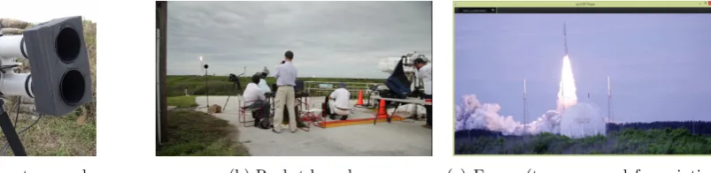
The University of Warwick and goHDR were invited to film a launch in July 2013. As the dynamic range in a rocket launch is a lot brighter than 14 stops, two Canon 5D Mark IIIs were mounted “bottom-to-bottom” using a special mount, Figure 2a. As can be seen, rubber foam was placed between the lenses to minimise vibrations. An additional challenge was that, for safety reasons, the capture team was 3 miles from the launch site. A 400mm lens together with a 2×focal length extender was used for each camera. Figure 2b shows the capture in progress, while Figure 2c shows a tone mapped frame of the launch. The Canon 5D Mark IIIs, each using (different) alternative exposures, gave a combined dynamic range of approximately 18 stops. This was unfortunately not enough to fully capture all the detail in the flume of the rocket as well as the surrounding scene.
(a) Camera system used (b) Rocket launch (c) Frame (tone mapped for printing)
[image:5.595.140.542.444.542.2]from the launch
Figure 2
3.1.2 Second generation HDR video capture system
The experience with the rocket launch clearly showed (a) the need to be able to capture as wide a dynamic range as possible, to ensure all the detail in the scene was subsequently available and (b) the limitations of a two-camera solution. In particular, the two Canon 5D Mark III system, was cumbersome, easily moved out of alignment, and introduced parallax effects.
capture software to set the exposure controls itself. This removed the need for user intervention and gave a “hands-off HDR camera solution. In addition, the 10-bit SDI interface available from the camera delivered more dynamic range to the merging algorithm, providing only a three-exposure merge. The single HDR-enabled Flare system has been measured as capable of capturing 18.2 stops by the Kennedy Space Center.
3.2 Real-time HDR video compression
In order to be able to compress and stream HDR video using commodity hardware a traditional HDR video encoding method was adapted and accelerated to give the performance required. The goHDR compression method25 is well suitable for acceleration as it exploits existing high performance video encoders. The goHDR
method, being a two-stream method, splits the HDR video frame into 2×8-bit frames which can then each be fed into optimised CPU based video encoders such as x26432or even take advantage of embedded hardware video
[image:6.595.147.468.276.411.2]encoders present on many modern GPUs and in the SoCs (system of chips) present in high-end mobile phones. Another advantage of using legacy video codecs is the ability to move the compressed HDR video data through existing broadcast pipelines as well as via robust streaming solutions such as HLS (HTTP Live Streaming) and RTSP (Real Time Streaming Protocol). This means that the HDR data can be streamed over the internet using existing systems in order to be displayed on any device, including mobiles.
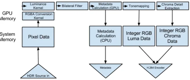
Figure 3: goHDR-classic HDR video compression method system architecture.
Figure 3 shows the block diagram for the system architecture used for goHDR-classic. The method was originally designed for CPU computation and therefore a number of operations needed to be adapted for use in a parallel, GPU based implementation, in order for real-time compression and streaming to be achieved. As Figure 3 shows, some stages of the method are suitable for the independent pixel operations for GPU acceleration, however others, such as the bilateral filter, required significant optimisation in order to be efficient on a GPU.
The GPU implementation was written in OpenCL as the implementation is cross-platform. This has the key advantage that the method can be ported to other platforms, including FPGAs and mobile devices in a straightforward manner. Each stage in Figure 3 was implemented as a single OpenCL kernel.
The HDR RGB 32-bit floating point data was expanded to RGBA data for improved performance via a novel kernel which packs three channel image data into a four channel buffer, then on a parallelisable basis expands it to the native four channel format required by OpenCL. While RGB data can be converted at speeds up to real-time on the CPU, this method provided a significant reduction in overall system latency. The luminance was computed via convolution with the Rec. 601 luminance primaries as follows:
Y = 0.299·R+ 0.587·G+ 0.114·B (1)
Subsequently an optimised ‘star’ bilateral filter was applied. This star bilateral filter is an optimised combination of the separable bilateral filter and the box bilateral filter.33, 34 It is designed to scale linearly with
(a) Box bilateral filter with half window size of 5.
(b) Star bilateral filter with half window size of 5.
(c) Optimised method of image statistic calculation based on mip-mapping.
Figure 4: (a) & (b) The box and star methods of bilateral filtering showing sampled pixels in green surrounding the filter target in red. (c) Using this method multiple statistics can be generated for the entire frame in a parallel fashion.
PSNR in compressed footage was considered acceptable for the≈82% average gain in performance (see Table 2) which enables pipeline to achieve real-time performance.
The filtered luminance is used to compute a number of statistics from the frame to aid compression. These include the minimum, maximum, average and harmonic mean values. In order to efficiently calculate single values for each frame a mip-mapping, pyramid-like scheme was used as shown in Figure 4c. Such a scheme removed the need for a costly copy of the image from GPU memory back to system memory and also avoided the use of GPU atomic variables which are a significant performance bottleneck.
The filtered luminance was then tone mapped using an invertible tone mapper,35in order to store the full
range of luminance in the frame. The residual information, along with the chrominance, are then calculated and stored in a second frame. The two frames are then passed to two individual video encoders, such as H.263, AVC, or VP9 for compression and transmitted either as two discrete video streams in a single container, or else as a double-sized frame.
3.3 HDR video on commercially available displays
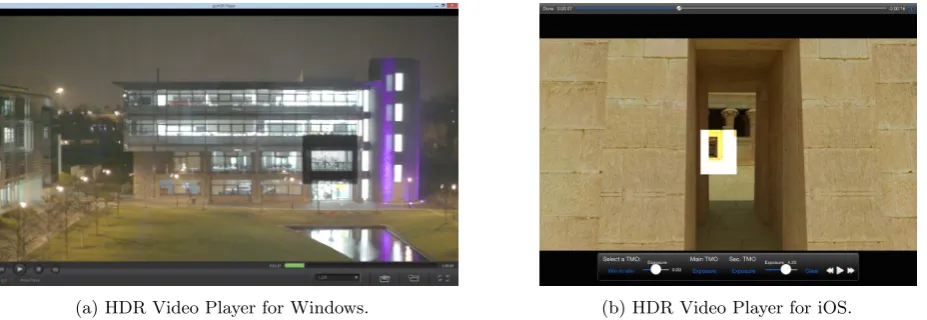
[image:7.595.84.531.78.233.2](a) HDR Video Player for Windows. (b) HDR Video Player for iOS.
[image:7.595.68.532.486.646.2]As discussed earlier, although commercial HDR displays such as the SIM2 are available,7 for the foreseeable future the majority of HDR video content will be viewed on LDR displays, including mobile devices and emerging 10-bit LDR displays capable of up to 1,000 cd/m2 peak luminance. A dedicated HDR Video Player was thus
developed to provide an enhanced viewing experience of HDR content even on such LDR displays. Capable of running on a wide range of platforms, including Android and iOS mobile devices, this player (see Figure 5) has the following functionality:
• Support for a wide range of LDR and HDR video formats and image sequences.
• The ability to select the display device as LDR, SIM2 or newer 10-bit displays with an HDR transfer function.
• A choice of tone mapping operators to suit display and content.
• The ability to select and display an exposure of the HDR scene.
• Windows-in-windows can be included and examined at different exposure values as shown in Figures 5a and 5b.
The player thus provides a viewer the opportunity for an interactive personalised experience. If the dynamic range of the delivered footage is larger than that of the display a dynamic choice of tone mappers can be selected, or the viewer can explore scene detail in the different exposures, including setting an appropriate exposure for an object or part of the scene to ensure that the associated detail can be clearly seen. This will allow, for example, the viewer to see their favourite player, no matter what the lighting conditions of the actual scene are, or as Figure 5a shows, the ability to simultaneously watch a person in a lit room of a building at night as well as one on the outside.
4. RESULTS
This section presents the performance results obtained with our commodity end-to-end HDR video pipeline. The results were calculated using an Intel i5-3570K CPU and a Geforce GTX 750 Ti graphics card, as examples of mid-range commodity computing hardware. Six HDR video sequences, shown as thumbnails in Figure 6, were selected to represent a range of HDR video test cases.
For real-time performance in a pipeline the requirement is for each stage of processing to introduce as little latency as possible. At the very least, the latency must equate to a processing frame-rate equal or greater than the target rate of the video (typically between 24 and 30 frames per second). Any improvement above that figure will reduce the overall latency of the system but is not essential.
In Table 2a the latency incurred by the proposed HDR video pipeline described above is measured, both running on a CPU and subsequently a GPU. These results are also presented in terms of overall frame-rate in Figure 7. Furthermore, the method is evaluated separately for both the box bilateral and star bilateral filters described above, as well as a control evaluation in which no filtering is performed. From these results it is clear that the bilateral filtering represents the bulk of the processing time in the method, and that the use of the star bilateral filter allows real-time 30fps performance to be achieved when a GPU is used.
Figure 8 shows an average calculation of the PSNR metric under the three filter options in the previous graph, from the results in Table 2a. This figure shows that the quality of the image output from the HDR encoding section of the system is minimally affected by the choice of filter. As no subsequent video encoding occurs in this test system, the benefit of the bilateral filter to the process overall is not demonstrated.
CGRoom Welding Tears of Steel Seine Jaguar Mercedes
Box Bilateral 0.624 0.647 0.482 0.650 0.735 0.735
Star Bilateral 0.252 0.250 0.210 0.277 0.284 0.277
No Filter 0.072 0.073 0.079 0.101 0.099 0.097
(a) CPU Latency (Seconds)
CGRoom Welding Tears of Steel Seine Jaguar Mercedes
Box Bilateral 0.045 0.045 0.036 0.049 0.049 0.048
Star Bilateral 0.026 0.025 0.021 0.025 0.026 0.025
No Filter 0.013 0.013 0.010 0.013 0.014 0.013
(b) GPU Latency (Seconds)
CGRoom Welding Tears of Steel Seine Jaguar Mercedes
Box Bilateral 60.75 53.25 40.35 61.54 51.66 53.70
Star Bilateral 60.73 52.99 40.30 61.17 51.24 53.42
No Filter 60.92 54.93 39.81 60.47 50.32 51.98
[image:9.595.119.494.103.337.2](c) PSNR (dB)
Table 2: Per-frame latency incurred in HDR encoding with box bilateral versus star bilateral implemented on GPU (a) and CPU (b), and the penalty incurred to quality (c).
(a) CGRoom: 1920×1080; 27.81 stops (b) Welding: 1920×1080; 21.52 stops (c) Tears of Steel: 1920 × 800; 18.40 stops
[image:9.595.62.550.434.654.2](d) Seine: 1920×1080; 20.93 stops (e) Jaguar: 1920×1080; 18.31 stops (f) Mercedes: 1920×1080; 22.29 stops
0 20 40 60 80 100 120
CGRoom Welding Tears of Steel Seine Jaguar Mercedes
FP
S
No Filter (GPU)
Star Bilateral (GPU) Box Bilateral (GPU)
No Filter (CPU)
Star Bilateral (CPU)
[image:10.595.63.550.101.323.2]Box Bilateral (CPU)
Figure 7: Performance comparison of Star and Box Bilateral filters on CPU and GPU.
50.00 50.50 51.00 51.50 52.00 52.50 53.00 53.50 54.00 54.50 55.00 Av
g
PS
NR
(d
B)
Figure 8: Average PSNR achieved using the Box and optimised Star Bilateral filters.
0.00 5.00 10.00 15.00 20.00 25.00 30.00 35.00 40.00
CPU Metadata
GPU Metadata
Av
g
Sp
ee
d
(F
PS
[image:10.595.102.258.405.637.2])
[image:10.595.353.511.406.635.2]5. CONCLUSION
To achieve the full potential of the step change in image quality that HDR video provides, it must be possible for a wide range of the population to be able to capture and display their own HDR video content. State-of-the-art cameras, such as the ARRI Alexa and the Red Epic, which can directly capture a wide dynamic range, and HDR displays, such as the SIM2 are out of the price range of most consumers. This paper has presented a complete end-to-end HDR pipeline using off-the-shelf hardware. This integrated pipeline can include everything from capture to post-production, archival and storage, compression, transmission, and display in a straightforward manner. As the results show, it is possible to achieve real-time performance along this entire pipeline and deliver the full range of HDR data to any display. Having the full range of HDR data available at the display allows for novel viewing experiences. One of the key challenges still facing HDR video capture using multiple exposures on commodity cameras is ghosting. This is especially a problem with mobile devices where the camera and the scene may both be moving. Future work will investigate improved real-time deghosting algorithms to provide even better quality HDR video on mobile devices.
ACKNOWLEDGMENTS
The work is partially supported by EU COST Action IC1005. Chalmers and Debattista are Royal Society Industrial Fellows. We would like to thank Brian Karr and the Advanced Imaging Lab of the Kennedy Space Center for their valuable assistance when filming the rocket launch.
REFERENCES
[1] Ward, G., “Real pixels,”Graphics Gems II, 80–83 (1991).
[2] Larson, G. W., “Logluv encoding for full-gamut, high-dynamic range images,” J. Graph. Tools3, 15–31 (Mar. 1998).
[3] Industrial Light & Magic, “OpenEXR.”http://www.openexr.com/ (October 2014).
[4] Banterle, F., Artusi, A., Debattista, K., and Chalmers, A., [Advanced High Dynamic Range Imaging: Theory and Practice], A. K. Peters, Ltd., Natick, MA, USA, 1st ed. (2011).
[5] Benoit, A., Alleysson, D., Herault, J., and Le Callet, P., “Spatio-temporal tone mapping operator based on a retina model,” in [Computational Color Imaging], 12–22, Springer (2009).
[6] Boitard, R., Bouatouch, K., Cozot, R., Thoreau, D., and Gruson, A., “Temporal coherency for video tone mapping,” in [SPIE Optical Engineering+ Applications], 84990D–84990D, International Society for Optics and Photonics (2012).
[7] SIM2 Multimedia S.p.A., “Sim2 high dynamic range display series.”http://www.sim2hdr.com/(July 2015). [8] Seetzen, H., Heidrich, W., Stuerzlinger, W., Ward, G., Whitehead, L., Trentacoste, M., Ghosh, A., and
Vorozcovs, A., “High dynamic range display systems,” in [ACM Transactions on Graphics (TOG)],23(3), 760–768, ACM (2004).
[9] Guthier, B., Kopf, S., and Effelsberg, W., “A real-time system for capturing hdr videos,” in [Proceedings of the 20th ACM International Conference on Multimedia],MM ’12, 1473–1476, ACM, New York, NY, USA (2012).
[10] Debevec, P. E. and Malik, J., “Recovering high dynamic range radiance maps from photographs,” in [Proceedings of the 24th Annual Conference on Computer Graphics and Interactive Techniques],SIGGRAPH ’97, 369–378, ACM Press/Addison-Wesley Publishing Co., New York, NY, USA (1997).
[11] Chalmers, A., Bonnet, G., Banterle, F., Dubla, P., Debattista, K., Artusi, A., and Moir, C., “High-dynamic-range video solution,” in [ACM SIGGRAPH ASIA 2009 Art Gallery & Emerging Technologies: Adaptation],SIGGRAPH ASIA ’09, 71–71, ACM, New York, NY, USA (2009).
[12] Tocci, M. D., Kiser, C., Tocci, N., and Sen, P., “A versatile hdr video production system,” in [ACM Transactions on Graphics (TOG)], 30(4), 41, ACM (2011).
[13] Karr, B., Chalmers, A., and Debattista, K., “High dynamic range digital imaging of spacecraft,” in [High Dynamic Range - From Acquisition to Display and Applications], Dufaux, F., Le Callet, P., Mantiuk, R., and Mrak, M., eds. (2015). Forthcoming.
[15] McNamee, J., Hatchett, J., Debattista, K., and Chalmers, A., “Real time delivery of hdr video,”CVMP
(2014).
[16] Chalmers, A., McNamee, J., Hatchett, J., Mukherjee, R., Olaizola, I., and Debattista, K., “12 bits is simply not enough for hdr video!,”BEC, NAB(2015).
[17] Mantiuk, R., Krawczyk, G., Myszkowski, K., and Seidel, H.-P., “Perception-motivated high dynamic range video encoding,”ACM Trans. Graph.23(3), 733–741 (2004).
[18] Motra, A. and Thoma, H., “An adaptive logluv transform for high dynamic range video compression,” in [Image Processing (ICIP), 2010 17th IEEE International Conference on], 2061–2064, IEEE (2010). [19] Zhang, Y., Reinhard, E., and Bull, D., “Perception-based high dynamic range video compression with
optimal bit-depth transformation,” in [Image Processing (ICIP), 2011 18th IEEE International Conference on], 1321–1324, IEEE (2011).
[20] Miller, S., Nezamabadi, M., and Daly, S., “Perceptual signal coding for more efficient usage of bit codes,” in [SMPTE Conferences],2012(10), 1–9, Society of Motion Picture and Television Engineers (2012).
[21] Borer, T., “Non-linear opto-electrical transfer functions for high dynamic range television,” BBC White Paper(2014).
[22] Mantiuk, R., Efremov, A., Myszkowski, K., and Seidel, H.-P., “Backward compatible high dynamic range mpeg video compression,” in [ACM Transactions on Graphics (TOG)],25(3), 713–723, ACM (2006). [23] Ward, G. and Simmons, M., “Jpeg-hdr: A backwards-compatible, high dynamic range extension to jpeg,” in
[ACM SIGGRAPH 2006 Courses], 3, ACM (2006).
[24] Lee, C. and Kim, C.-S., “Rate-distortion optimized compression of high dynamic range videos,” in [Signal Processing Conference, 2008 16th European], 1–5, IEEE (2008).
[25] Banterle, F., Artusi, A., Debattista, K., Ledda, P., Chalmers, A., Edwards, G., and Bonnet, G., “Hdr video data compression devices and methods,” (June 27 2008). EP Patent 2,144,444.
[26] Ruppertsberg, A. I., Bloj, M., Banterle, F., and Chalmers, A., “Displaying colourimetrically calibrated images on a high dynamic range display,”Journal of Visual Communication and Image Representation18(5), 429–438 (2007).
[27] “Magic lantern.” http://www.magiclantern.fm/(July 2015).
[28] Ram´ırez Orozco, R., Martin, I., Loscos, C., and Vasquez, P.-P., “Full high-dynamic range images for dynamic scenes,”Proc. SPIE8436, 843609–843609–16 (2012).
[29] Granados, M., Kim, K. I., Tompkin, J., and Theobalt, C., “Automatic noise modeling for ghost-free hdr reconstruction,”ACM Trans. Graph.32, 201:1–201:10 (Nov. 2013).
[30] “COST Action IC1005.”http://ic1005-hdri.inesctec.pt/(July 2015).
[31] Luthra, A., Francois, E., and Husak, W., “Draft requirements and explorations for hdr/wcg content distribution and storage,”ISO/IEC JTC1/SC29/WG11 MPEG2014 N14510(2014).
[32] VideoLAN Organisation, “x264.”https://www.videolan.org/developers/x264.html(July 2015). [33] Pham, T. Q. and Van Vliet, L. J., “Separable bilateral filtering for fast video preprocessing,” in [Multimedia
and Expo, 2005. ICME 2005. IEEE International Conference on], 4–pp, IEEE (2005).
[34] Tomasi, C. and Manduchi, R., “Bilateral filtering for gray and color images,” in [Proceedings of the Sixth International Conference on Computer Vision],ICCV ’98, 839–, IEEE Computer Society, Washington, DC, USA (1998).