Solidi
fi
cation Structure of Al
Cu and Sn
Cu
Sb Alloys Obtained by Casting
through Induction Stirring Using Permanent Magnet
+1Fumitaka Otsubo
1,+2, Satoshi Nishida
2,+3and Hidenori Era
1 1School of Engineering, Kyushu Institute of Technology, Kita-Kyushu 804-8550, Japan2Graduate School of Engineering, Kyushu Institute of Technology, Kita-Kyushu 804-8550, Japan
Permanent magnetic stirring is superior in terms of cost and operability compared with electromagnetic stirring. However, it is applied only to melting furnace. In this study, attempts were made to apply permanent magnetic stirring molten metal, and the effects of the stirring on grain refinement, increase in hardness, and suppression of porosity were investigated. We used a stirring device developed by ourselves and two alloys with different solidification morphologies and specific gravities (μ). Results showed that needlelike crystals were cut off in SnCuSb alloy (μ=7.4). On the other hand, the growth of columnar crystals was inhibited, and grain refinement and a region growing with equiaxed crystals were observed in AlCu alloy (μ=2.7) due to the stirring. Furthermore, increased hardness and suppression of porosity were confirmed with the increase in the rotating velocity of magnets in both alloys. Theoretical calculations showed that the molten metal near the mold was directly stirred by Lorentz force, but other regions were indirectly stirred by theflow of force from the directly stirring.
[doi:10.2320/matertrans.F-M2014804]
(Received September 24, 2013; Accepted February 6, 2014; Published April 25, 2014)
Keywords: casting, stirring, permanent magnet, solidification structure, refinement, tincopperantimony alloy, aluminumcopper alloy, porosity
1. Introduction
Refinement of a cast structure, improvements in mechani-cal properties and suppression of inner defects are expected through the stirring of molten metal poured into a cast mold. In recent years, electromagnetic stirring has been widely used for improvements of cast materials.1,2) However,
electro-magnetic stirring has problems; adjustment of the stirring rate is difficult and high electrical power is necessary to form a magnetic field. Therefore, the development of stirring is necessary to improve these disadvantages. A new stirring method to form magnetic fields by turning a permanent magnet along the wall of a melting furnace was proposed.3) This method has several excellent features; electricity consumption can be reduced by 10% and the adjustment of the stirring velocity is easy, but it is difficult to apply the stirring to products with large diameters compared with electromagnetic stirring. This method is used for the melting furnace to melt raw material rapidly and to homogenize chemical composition. There is no report thus far that this method has been applied to the refinement of the grain size, strengthening and quality stabilization. In this study, the effect of refinement of grain size, improvements in mechani-cal properties and reduction of porosity in castings through stirring with a permanent magnet were investigated.
2. Principle
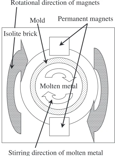
Figures 1 and 2 show the top view of the stirring device and the cross-section of the mold, respectively. Rotation of the permanent magnet gives rise to eddy currents inhibiting magnetic flux penetrating for unit time by Lorentz’s law in
the mold. Lines of magnetic force occur at each loca-tion accompanied by eddy current generaloca-tion. Applying Fleming’s left-hand law using lines of magnetic force and the eddy current, the Lorentz force of repulsion and attraction act in the forward and reverse directions of the magnet, respectively. Thus, molten metal is stirred in the direction of magnetic rotation in the mold.
3. Experimental Procedure
3.1 Stirring device using permanent magnet
A schematic drawing of the device used is shown in Fig. 3.
Permanent magnets
Isolite brick
Molten metal
Stirring direction of molten metal
Mold
Rotational direction of magnets
Fig. 1 Schematic illustration of top view of stirring device.
+1This Paper was Originally Published in Japanese in J. JFS84(2012) 526.
+2Corresponding author, E-mail: otsubo@post.matsc.kyutech.ac.jp
+3Graduate Student, Kyushu Institute of Technology. Present address:
[image:1.595.332.520.348.603.2]The rotary device of the magnet was prepared in-house by us. A neodymium magnet in the shape of a cube with 15 mm side turns along the mold. The magnet is rotated at a 20 mm height from the bottom of the mold and different magnetic poles face each other.
3.2 Specimen
Sn4%Cu6%Sb and Al2%Cu (in mass%) alloys were used for the casting. These alloys have different solidification morphologies and specific gravity (μ) values. The structures of SnCuSb (μ=7.4) and AlCu (μ=2.7) alloys consist of some phases and an almost dendritic single phase, respec-tively. An alumina crucible was prepared for the mold with inner diameter, wall thickness and total height of 36, 8 and 100 mm, respectively. Casting ingot heights of the SnCuSb and AlCu alloys are 55 and 50 mm, respectively. The maximum rotating velocity of the magnet for the SnCuSb and AlCu alloys was 1100 and 1200 rpm, respectively.
3.3 Cooling curve
The temperature of the outside and center regions at 20 mm height from the bottom of the ingot was measured by thermocouples. The solidification time was defined as the time until the temperature fell below the solidification temperature after reaching the solidification temperature.
3.4 Observations of structure
The microstructure of the SnCuSb alloy ingot was observed along the longitudinal section after etching with aqua regia. The macrostructure of the AlCu ingot was observed along the longitudinal sections and cross sections at 12 mm height from the bottom after etching with a 50 vol% NaOH solution. The center regions at 2, 12 and 22 mm heights from the bottom of the ingot are termed the bottom, center and upper regions, respectively. The region near the surface of the ingot at 12 mm height from the bottom is called the outside region.
3.5 Hardness tests and porosity measurements
Hardness was evaluated by a Vickers hardness tester. The hardness was averaged for the hardness numbers obtained from eight regions of equal distance. Tests for SnCuSb and AlCu alloys were carried out under 0.1 and 0.2 kgf weights, respectively. Also, the porosity measurement was applied using the JIS-G-0555 method from the microstructure images of the outside and center regions of the alloys (Sn CuSb alloy: magnifications of ©200 and AlCu alloy: magnifications of©40).
4. Result and Discussion
4.1 SnCuSb alloy
Figure 4 shows cooling curves of the SnCuSb alloy from molten metal at 703 K. The solidification time decreases from 100 to 70 s at the center region under stirring at 1100 rpm. Also, it is seen that the cooling rate under stirring at 1100 rpm on the outside region was high compared with no stirring. Furthermore, the solidification time had a tendency to decrease with increasing stirring rate supporting the result under stirring at 900 rpm. This is because the molten metal cools rapidly due to improvement in the thermal conduction of the molten metal to the mold by the stirring through the rotation of the magnet.4)
Figure 5 shows the microstructures of the center and outside regions solidified under stirring at 0 and 1100 rpm in the SnCuSb alloy. Coarse needle-like primary crystals (Cu6Sn5) are observed in the whole area of the alloy under
stirring at 0 rpm (Figs. 5(a) and 5(c)). On the other hand, a lot of short needle-like crystals are observed in the center region under stirring at 1100 rpm (Fig. 5(b)). The fraction of granular crystals was higher in this case compared to no stirring (Fig. 5(b)). This indicates that the dividing of crystals occurring by collision among crystals and the collision of crystals with the mold through stirring are responsible for this. Furthermore, it was found that needle-like crystals are hardly observed in the outside region and the granular crystals were dispersed in the matrix (Fig. 5(d)).
Mold
Permanent
magnet
Isolite brick
Rotary drive device
Fig. 3 Schematic of stirring device.
Permanent magnet
Lorentz force (attractive) Lorentz force (repulsive)
Magnetic force lines Rotational direction of magnet
[image:2.595.312.537.71.291.2] [image:2.595.60.280.73.309.2]Figure 6 shows microstructures of the upper and bottom regions under stirring at 0 and 1100 rpm in the SnCuSb alloy. Coarse needle-like crystals, similar to the results shown in Fig. 5, are observed in the bottom and upper regions under no stirring (0 rpm) (Figs. 6(a) and 6(c)). A granular structure is hardly observed under the stirring at 1100 rpm in the bottom region, different from the center and outside regions of the mold (Fig. 6(b)). This result suggests that the time was not sufficient to obtain the effects of the stirring because of rapid solidification in the bottom region of the mold. Furthermore, the same tendency as the center region was observed in the upper region (Fig. 6(d)). This indicated that the stirring had an effect on regions without direct stirring (without the outside region) as well. It was found that the effect of the stirring was the greatest in the outside region. Also, the effect became weak in order of the center and upper regions. Furthermore, the effect is hardly seen in the bottom region. Therefore, the area affected by the stirring with the permanent magnet is local in the SnCuSb alloy.
Figure 7 shows micro-vickers hardness values of the Sn CuSb alloy. The hardness of the SnCuSb alloy increased with increasing rotating velocity regardless of the measuring region. Hardness increased remarkably in the outside and bottom regions. Figure 8 shows the porosity in the SnCuSb alloy. The porosity of the SnCuSb alloy decreased with increasing rotating velocity in the center and outside regions. Furthermore, porosity in the outside region decreased remarkably compared with the center region under the same velocity of the rotation. This indicates that molten metal is supplied rapidly by the stirring. Therefore, it seems that hardness increases due to decreasing porosity, rapid cooling rate in the outside region and accumulation of granular crystals in the bottom region. It is concluded that hardness and porosity are greatly dependent on the rotating velocity of the magnet, thereby affecting the stirring.
4.2 AlCu alloy
Figure 9 shows cooling curves from the molten metal at 1023 K in the AlCu alloy. The solidification time decreased from 8 to 5 s in the center region and the cooling rate increased in the outside region at 0 and 1200 rpm rotation.
100µm 100µm
100µm 100µm
(a)
(b)
(c)
(d)
Fig. 5 Microstructures of SnCuSb alloys: (a) center region at 0 rpm, (b) center region at 1100 rpm, (c) outside region at 0 rpm, (d) outside region at 1100 rpm.
100µm 100µm
100µm 100µm
(a)
(b)
(c)
(d)
Fig. 6 Microstructures of SnCuSb alloys: (a) bottom region at 0 rpm, (b) bottom region at 1100 rpm, (c) upper region at 0 rpm, (d) upper region at 1100 rpm.
20 22 24 26
Outside Center
Upper Bottom
900 1100
0
Rotating velocity,
n
/rpmV
ickers hardness,
Hv
0.1
Fig. 7 Vickers hardness of SnCuSb alloys.
0 25 50 75 100 125 450
450 500 550
Outside
Center
Outside
(b) (a)
500
T
emperature,
T
/K
Center
Time,
t
/s
Solid-liquid coexistence regions
[image:3.595.63.276.67.279.2] [image:3.595.326.526.315.484.2] [image:3.595.53.283.323.504.2]This was the same tendency as in the AlCuSb alloy. Also, the solidification time decreased with increasing rotating velocity in the thermal analysis at 300 and 600 rpm.
Figure 10 shows macrostructures on the cross-section (Figs. 10(a) and 10(d)) and its schematic drawings (Figs. 10(e) and 10(f )) in the AlCu alloy under stirring at 0, 300, 600 and 1200 rpm. Long columnar crystals were
grown from the surface of the ingot and coarse equiaxed crystals were formed in the center area of the ingot in the alloy under no stirring (0 rpm) (Figs. 10(a) and 10(e)). On the other hand, columnar crystals were grown forward to the inversion direction of the magnet with gradient to the outside region and the columnar crystals became shorter in the stirred ingot (Figs. 10(b) through 10(d) and 10(f )). This is the same result as in the previous reports of electromagnetic stirring.5,6) Therefore, from the results in this study, it was confirmed that sufficient stirring of the molten metal occurred by the stirring of the permanent magnet.
[image:4.595.66.271.169.608.2]Figure 11 shows the macrostructures of the longitudinal section in the AlCu alloy under stirring at 0, 300, 600 and 1200 rpm (Figs. 11(a) through 11(d)). A long columnar and coarse equiaxed structure similar to the structure of the cross-section (Fig. 10(a)) was observed in the area with rotation of the magnet at 0 rpm (Fig. 11(a)). It is seen that equaxied crystals became finer with increasing rotating velocity and the area of the equiaxed crystals were enlarged in the stirred alloy (Figs. 11(b) through 11(d)). This indicates that the dendrites that formed in the early stage of solidification were broken by the flow due to the stirring and subsequently became the nuclei of the crystal. The formation of equiaxed crystals in the AlCu alloy depends on the heatflux andflow in the solidliquid coexistence state.4)Also, the refinement of equiaxed crystals in this study depends on increasing the temperature gradation due to the stirring. Refinement of equiaxed crystals was observed in the upper region where the melt was not directory stirred. However, the effect of the refinement is hardly observed in the bottom region of the Al Cu alloy, which is similar to the case of the SnCuSb alloy. Thererfore, it is found that the effect of the stirring in the Al Cu alloy extends to the whole volume except for the bottom region. Also, a shrinkage cavity has a tendency to become larger with increasing rotating velocity.
Figure 12 shows micro-vickers hardness values in the Al Cu alloy. The hardness increased in the alloy by stirring. Figure 13 shows the porosity in the AlCu alloy. The porosity decreased with increasing rotating velocity and decreased remarkably in the outside region, which is also similar to the case of the SnCuSb alloy. Thus, the hardness depends on the fraction of porosity. This means that increasing the cooling rate in the outside region by increasing the rotating velocity of the magnet yields the increased hardness.
0 5 10 15 20
850 900 950
900
850
Center
Outside
Center
Outside
Solid-liquid
coexistence regions (a)
(b)
T
emperature,
T
/K
Time,
t
/sFig. 9 Cooling curves just after pouring: (a) 0 rpm, (b) 1200 rpm.
10mm
(a) (b)
(c) (d)
Magnet Magnet
[image:4.595.70.269.173.344.2](e) (f)
Fig. 10 Macrostructures ((a) through (d)) and schematic illustrations ((e) and (f )) of cross-section from bottom for AlCu alloys. (a) 0 rpm, (b) 300 rpm, (c) 600 rpm, (d) 1200 rpm, (e) without stirring, (f ) with stirring.
0 0.5 1 1.5 2 2.5
Porosity
, %
Outside Center
900 1100 0
Rotating velocity,
n
/rpm [image:4.595.64.274.370.591.2] [image:4.595.59.541.638.761.2]4.3 Magnetic flux density in mold and force affecting molten metal
4.3.1 Calculation for force by magnetflux
The magneticflux density was calculated by eq. (1) when an NdFeB magnet (506 mT) with the same shape was set on opposite sides across the mold.7)
BðXÞ ¼B³r
tan1 AB
2Xpffiffiffiffiffiffiffiffiffiffiffiffiffiffiffiffiffiffiffiffiffiffiffiffiffiffiffiffiffiffiffi4X2þA2þB2
tan1 AB
2ðLþXÞp4ffiffiffiffiffiffiffiffiffiffiffiffiffiffiffiffiffiffiffiffiffiffiffiffiffiffiffiffiffiffiffiffiffiffiffiffiffiffiffiffiffiffiffiðLþXÞ2þA2þB2
ð1Þ
Here, Br is the magnetic flux density of the permanent
magnet; A, B and L represent the size of the permanent magnet; and X is the distance from the center of the mold. First, 506 mT was substituted forBr, 0.015 m was used forA,
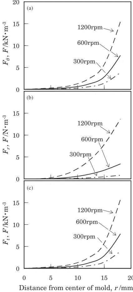
Band L, andXwas substituted by ¹0.026 to 0.026 m. The Lorentz force affecting the tangential and radial directions of the molten metal in the mold was calculated by eqs. (2) and (3) using the magnetic flux density calculated using eq. (1).8)
Fª ¼12·½rB2 ð2Þ
Fr¼18·2½2r3®vB2 ð3Þ
Here,FªandFrare the Lorentz forces affecting the tangential and the radial directions for the molten metal in the mold, respectively. Also, · is the electrical conductivity of aluminum,½ is the rotating velocity of the magnet,r is the distance from the center of the mold, B is the magnetic flux density, and ®vis the kinematic viscosity of aluminum.
In this study, 5 Hz (300 rpm), 10 Hz (600 rpm), and 20 Hz (1200 rpm) were used for ½. Also, values of 37.2© 106³m¹1 and 0.2©10¹6m2/s were used for · and ®
v,
respectively.9)The magneticflux density,B, depending on the
distance from the center of the mold was calculated by the change inr, andFª andFr were obtained usingB.
[image:5.595.49.547.70.232.2]4.3.2 Calculated results
Figure 14 shows the magneticflux density as a function of distance from the center of the mold. The magnetic flux density in the mold decreases abruptly at 2 mm distance from the surface of the mold in the central direction and subsequently decreases gradually. Therefore, a higher magnetic flux density affects the molten metal in the mold when the thickness of the mold wall and the inner diameter of the mold become smaller.
Figure 15 shows the force affecting the molten metal in the cylindrical mold as a function of the distance from the center. Lorentz forces increase with increasing rotating velocity of the magnet, whereas Lorentz forces decrease with a shift 30
35 40 45 50 55
Upper Outside Center Bottom
300 600 1200
0
Rotating velocity,
n
/rpmV
ickers hardness,
Hv
[image:5.595.72.270.280.448.2]0.2
Fig. 12 Vickers hardness of AlCu alloys.
0 5 10 15
Porosity
, %
Center
Outside
0 300 600 1200
Rotating velocity,
n
/rpmFig. 13 Porosity of AlCu alloys.
10mm
Magnet
(a) (b) (c) (d)
[image:5.595.329.523.283.450.2] [image:5.595.54.291.565.619.2]from the outside to the center according to the Lorentz force (Fª) affecting the tangential direction for the molten metal in the mold (Fig. 15(a)). The Lorentz force (Fr) affecting the molten metal in the mold in the radial direction (Fig. 15(b)) shows a tendency similar to the Lorentz force (Fª) in the tangential direction. However, the degree of the force was small, about 1/1000 of the force (Fª). Therefore, the Lorentz force affecting the radial direction hardly contributes to the molten metal so that the effect of stirring using the permanent magnet on the molten metal is not expected. Furthermore, the resultant force (jF!ªþF!rj) of the Lorentz force affecting the tangential and the radial directions shows a tendency similar to the Lorentz force affecting the tangential direction (Fig. 15(c)). Consequently, the effect of the stirring depends remarkably on the Lorentz force affecting the tangential direction. It is concluded that the AlCu alloy is stirred directly by the Lorentz force in the outside of the molten metal near the rotating magnet. On the other hand, the alloy in the upper, central and lower regions far from the magnet is stirred indirectly by fluidity generated at the outside region. Also, indirect stirring is difficult in the SnCuSb alloy compared with the AlCu alloy because of the large specific gravity (μ=7.4). The effect of stirring appeared markedly only in the outside region near the magnet, as shown in Figs. 58. It is clear that the effect of the stirring using the permanent magnet depends on the specific gravity of the molten metal in addition to the magnetflux and the rotating velocity of the magnet.
5. Conclusions
A stirring device using a permanent magnet was designed and was prepared in-house by us. Stirring of the molted metal was carried out during casting. The influence of the stirring using the permanent magnet on ingots having different solidification morphologies and specific gravity values was studied. The following conclusions were obtained.
(1) Stirring of the molten metal brings about shortening of the solidification time.
(2) When the SnCuSb alloy was stirred, the primary lath
crystal was broken to become granular crystals. (3) When the AlCu alloy was stirred, fine equiaxed
crystals were formed in the whole ingot and its area was extended.
(4) Hardness increased with increasing rotating velocity of the magnet and porosity decreased in the alloys. (5) The molten metal is stirred directly in the outside region
near the magnet. On the other hand, the molten metal far from the magnet is stirred indirectly by fluidity generated in the outside region.
Acknowledgement
The authors wish to thank Mr. K. Yoshimoto, graduate student of Kyushu Institute of Technology, for experimental assistance.
0 5 10 15
0 5 10 15 20
0 5 10 15 0 5 10 15 20
(a)
1200rpm
600rpm
300rpm
1200rpm
600rpm
300rpm
(c) (b)
1200rpm
600rpm
300rpm
F
t,
F
/kN
m
-3
F
r,
F
/N
m
-3
F
,
F
/kN
m
-3
[image:6.595.63.282.72.253.2]Distance from center of mold, r /mm
Fig. 15 Lorentz force acting to molten metal: (a) tangential direction, (b) radial direction, (c) total force.
P
ermanent Magnet
P
ermanent Magnet
Mold wall
0 0.2 0.4 0.6
-26 -22 -18 -14 -10 -6 -2 2 6 10 14 18 22 26
Magnetic flux density
,
B
/ T
Distance from center, r / mm
[image:6.595.318.531.73.540.2]REFERENCES
1) V. Metan, K. Eigenfeld, D. Räbiger, M. Leonhardt and S. Eckert:
J. Alloy. Compd.487(2009) 163172.
2) K. Sakamoto, T. Yamamoto, H. Ohkawa, J. Nishi, Y. Hatsuse and K. Morita: Tetsu-to-Hagane73(1987) 321326.
3) K. Takahashi: ALUTOPIA36No. 11 (2006) 5661.
4) T. Suzuki, Y. Sasaki, T. Umeda and Y. Kimura: Tetsu-to-Hagane 65
(1979) 377382.
5) J. Szajnar:J. Mater. Process. Technol.157158(2004) 761764.
6) B. Chalmers:Solidification of Metals, translated by T. Okamoto and A. Suzuki, (Maruzen Company, Limited, 1971) pp. 248251 (in Japanese). 7) T. Okada, N. I. Wakayama, L. Wang, H. Shingu, J. Okano and T. Ozawa:
Electrochim. Acta48(2003) 531539.
8) Z. Chen, X. L. Wen and C. L. Chen:J. Alloy. Compd.491(2010) 395 401.