Control of Venturini Method Based Matrix
Converter in Input Voltage Variations
Hulusi Karaca, Ramazan Akkaya
Abstract—Matrix converter is a single-stage converter which
directly connects a three-phase voltage source to a three-phase load without dc-link components. Therefore, any harmonic distortion and imbalance in input voltage directly reflect to the output of the converter. Recently, many researchers have made an effort to cope with this problem.
In this paper, under distorted input voltage conditions, behaviors of the MC controlled with Venturini method are analyzed and a PI controller based compensation method to prevent negative effects of input voltage is proposed. Since the proposed method is based on closed loop control of the output currents, it not only reduces the output harmonic contents but also ensures a stable control of the load currents. Some results are presented to prove the effectiveness of the proposed compensation technique.
Index Terms—Matrix converter, ac-ac converter, Venturini
method, distorted input voltage, compensation.
I. INTRODUCTION
One of the most interesting members of the power converter family is the matrix converter providing directly ac-ac power conversion. Matrix converters firstly introduced in 1976 started to improve after the papers proposed by Venturini and Alesina in 1980 and 1989 [1], [2].
The matrix converter has received an increased amount of interest and has been studied intensely as an alternative to conventional indirect power converter systems in recent years, because it has outstanding advantages in following [3]-[5].
• Sinusoidal input and output currents
• No bulky dc-link reactive elements
• Possible with unity displacement factor for any load
• Four-quadrant operation
• Simple and compact design
• Regeneration capability.
These attractive properties have motivated researchers to study about the matrix converter [4].
However, the load side of the MC is directly affected by the distorted and/or unbalanced input voltages due to the lack
of dc intermediate circuit in the MC. The distorted and/or non-sinusoidal input voltages may cause the undesirable harmonic currents. The working performance of the load has deteriorated, when it is exposed to the harmonic and non-sinusoidal currents. If unfavorable effects of the distorted input voltages are eliminated in the MC, the popularity of the MC will more increase. Some papers have been presented to reduce the influences of the distorted input voltages [5]-[11].
Manuscript received December 25, 2008. Scientific Research Project Found of Selcuk University has been provided the financial support to this project.
H. Karaca is with the Department of Electrical and Electronics Engineering, Selcuk University, 42075, Konya, Turkey,
(corresponding author’s phone: +90-332-2233715; fax: +90-332-2410635; e-mail: [email protected]).
R. Akkaya is with the Department of Electrical and Electronics Engineering, Selcuk University, 42075, Konya, Turkey
(e-mail: [email protected]).
In this paper, a PI based compensation technique is proposed to get rid of the undesirable effects of the distorted input voltages for matrix converter controlled with Venturini modulation method. Since this technique improving the output performance of the MC performs closed loop control of the output current, three-phase output currents of the MC must be measured by using current sensors. The proposed method not only reduces the output harmonic contents but also ensures over-current protection and control for the load current. Some numerical and simulation results are presented to prove the effectiveness of the proposed compensation technique.
II. THE BASIC TOPOLOGY OF MATRIX CONVERTER The matrix converter is a single-stage converter, which is composed of an array of m x n bidirectional power switches, each connected between one phase of the input and one phase of the output. Theoretically, the number of input phases, m must be at least three, and the number of output phases, n can be chosen from one to infinity. The basic matrix converter topology which connects a three-phase voltage source to a three-phase load as shown in Fig. 1 is the most important converter from a practical point of view [12]. A matrix converter is an unlimited frequency changer, which can generate both smaller and bigger output frequency than input frequency of the converter. The output voltage waveforms are constructed by piecing together selected segments of the input voltage waveforms.
Each switch is characterized by a switching function, defined as follows [13].
⎪⎩ ⎪ ⎨ ⎧ =
closed is S
open is S (t)
S
Kj Kj
Kj 1
0
(1)
Each switchSKj ,K={A,B,C},j ={a,b,c}, can connect or
disconnect phase K of the input stage to phase j of the load. Output voltages can be synthesized by switching according to a proper combination of these switches.
jN
Fig. 1. The basic matrix converter topology Control of the matrix converter must comply with the
following basic two rules. Firstly, any two input terminals should never be connected to the same output line to prevent short-circuit, because the MC is fed by a voltage source. The other, an output phase must never be open-circuited, owing to the absence of a path for the inductive load current which leads to the over-voltages. The above two constraints can be expressed by (2).
1 = = =
∑
∑
∑
= == K A,B,C
Kc C , B , A K Kb C , B , A K
Ka(t) m (t) m (t)
m (2)
When these rules are provided, the 3 x 3 matrix converter can allow only 27 different switching states among the possible 512 switching combinations.
III. VENTURINI METHOD FOR MATRIX CONVERTER In 1980, Venturini and Alesina presented a converter, which consists of bidirectional power switches constructed as matrix and they introduced to as “matrix converter”. In addition to, they proposed a PWM modulation method for the control of matrix converter. The proposed method by these authors is known to as the Venturini method or the direct transfer function approach.
In Venturini method, the appropriate firing pulses to each of the nine bidirectional switches must be calculated to generate variable-frequency and/or variable-amplitude sinusoidal output voltages from the fixed-frequency and the fixed-amplitude input voltages.
In this paper, are the source voltages, are the source currents, are the load voltages with respect to the neutral point n of the load, and , are the load currents. Also, other variables have been defined to be used as a basis of the modulation and control strategies: , are the MC input voltages, , are the MC input currents, and v , are the load voltages with
respect to the neutral point N of the grid. sC
, sB sA,V V V c} B, {A, i , ii =
c} b, {a, j , = sC sB, sA,i i i
j ,
ij =
c} b, {a, j , vjn =
C} B, {A, i , vi = b,
{a,
jN
C}
If it is defined as the time during which switch is on and Ts: the sampling interval,
:
tKj SKj
s Kj Kj(t) t T
m = : duty
cycle of switchSKj, modulation matrix is given in (3).
⎥ ⎥ ⎥ ⎦ ⎤ ⎢ ⎢ ⎢ ⎣ ⎡ = ) t ( m ) t ( m ) t ( m ) t ( m ) t ( m ) t ( m ) t ( m ) t ( m ) t ( m ) t ( M Cc Bc Ac Cb Bb Ab Ca Ba Aa (3)
Under ideal conditions, the three-phase sinusoidal input voltages of the MC can be given as,
[
]
⎥ ⎥ ⎥ ⎦ ⎤ ⎢ ⎢ ⎢ ⎣ ⎡ π + ω π + ω ω = ) / t cos( ) / t cos( ) t cos( V ) t ( v i i i im i 3 4 3 2 (4)In accordance with this, each output phase voltages can be expressed by (5).
[
vjN(t)]
=[
M(t)][
vi(t)]
(5)In the same way, the input currents are also shown by expression in (6).
[
ii(t)] [
= M(t)] [
T io(t)]
(6)Where, [M(t)]T is the transpose matrix of [M(t)].
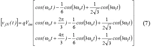
The amplitude of the output voltage is limited to 50 percent of the input voltage in the initial approach of Venturini method. To obtain a maximum voltage transfer ratio is added third harmonics of the input and output frequencies to the target output voltages as shown in (7).
[
]
(
)
(
)
(
)
(
)
(
)
(
)
⎥⎥ ⎥ ⎥ ⎥ ⎥ ⎥ ⎦ ⎤ ⎢ ⎢ ⎢ ⎢ ⎢ ⎢ ⎢ ⎣ ⎡ ω + ω − π + ω ω + ω − π + ω ω + ω − ω = t cos t cos ) t cos( t cos t cos ) t cos( t cos t cos ) t cos( qV ) t ( v i o o i o o i o o im jN 3 3 2 1 3 6 1 3 4 3 3 2 1 3 6 1 3 2 3 3 2 1 3 6 1 (7)Where, q is the voltage gain or voltage transfer ratio. By this way, a voltage transfer ratio of 0.866 which is maximum value can be obtained. The third-harmonic injection of the input and output frequencies into the target output voltages has no effect on the output line-to-line voltages. The target output voltage equals the average output voltage during each switching sequence.
If unity input displacement factor is required in the optimum-amplitude Venturini method [2], [5], the algorithm can be more simple in the form of (8) [3].
Lf
Cf
Input Filter
SAa SAb SAc
SBa SBb SBc
SCa SCb SCc
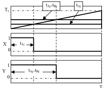
Fig. 2. Obtaining turn-on-time of the power switches
(
) (
{
}
{
}
)
3 4 3 2 0
3 3
2 2
1 3 1
2
π π = β =
=
⎥ ⎥ ⎦ ⎤ ⎢
⎢ ⎣ ⎡
ω β
+ ω +
+ =
, , , c , b , a j , C , B , A K
t sin t
sin q
q V
v v m
K
i K i m im
j K Kj
(8)
Then, duty cycles of bidirectional switches were calculated according to (9).
(
) (
⎥ ⎥ ⎦ ⎤ ⎢
⎢ ⎣ ⎡
ω β
+ ω +
+
= sin t sin t
q q V
v v T
t i K i
m im
j K s
Kj 9 3
2 3
2 3 1
2
)
(9)As shown Figure 2, Signals, X and Y are obtained by comparing saw-tooth with switching frequency and these calculated duty cycles. Final gate drive signals (SKj(t)),
determining turn-on-time of the power switches are obtained according to the logic statements in (10) by using duty cycles [13]. Consequently, only duty cycles of six switches are sufficient to calculate the gate signals for all of the power switches.
( )
( ) ( )
( ) ( )
=
= ⎫⎪
⇒ =
⎬
= + ⎪⎭
=
Aj Aj
Bj Aj Bj
Cj
S X
X t
S not X and Y
Y t t
S not X and not Y
(10)
[image:3.595.81.264.48.199.2]IV. THE PROPOSED COMPENSATION SCHEME FOR DISTORTED INPUT VOLTAGE CONDITIONS Modulation algorithms used in the MC have employed fixed switching patterns in sinusoidal input voltages. For certain frequency and/or amplitude values, duty cycles of the power switches are pre-calculated and placed into the table. But, since the negative effects of the input voltages reflect the output of the converter under the distorted input voltage conditions, using the fixed switching patterns are not appropriate. Therefore, duty cycles for switching patterns must be calculated instantaneously by measuring the output currents at each sampling period [10].
Fig. 3. PI feedback compensation scheme for matrix converter
In PI feedback compensation scheme, which is shown schematically in Fig. 3, the measured output currents are used to calculate the magnitude of the output current space vector (Ido) according to (11). If the input voltages of the MC are
sinusoidal and balanced, the output currents will be sinusoidal, too. Under this condition, Ido is constant.
However, if the input voltages of the MC are non-sinusoidal and unbalanced, Ido will be not constant due to the output
harmonic currents.
[
i (t) i (t) i (t)]
Ido oa2 ob2 oc2
3
2 + +
= (11)
Receiving inspiration from this idea, if Ido is kept constant,
the output of the converter is not affected by disturbances in the input voltages. The proposed compensation technique is based on this principle and a PI controller is employed for this purpose.
Accordingly, the PI controller system is fed by the instantaneous error of Ido (e(k)) in (12) and produces a
variable voltage-gain (q) according to the disturbance of the input voltage. Duty cycles of the power switches are calculated, substituting the variable-voltage-gain-value produced by the PI controller in (9).
( )
k[
I (k) I( )
k]
e = ref − do (12)
Block diagram of the PI controller based feedback system is clearly given in Fig. 4. The instantaneous value of the error can be calculated by subtracting the instantaneous current-space-vector Ido obtained by the measured
three-phase output current from the reference-current-space-vector Iref.
Fig. 4. Simulink diagram of PI controller based feedback system
The output of the PI controller system is the voltage-gain (q) and a saturation block has been added to the output of system, due to the magnitude of q can not exceed 0.866 and can not be negative.
tAj+tBj tAj
1 X 0
1 Y 0
tAj
tAj+tBj
Ts
Ts
3 Phase AC Source
Load
3 Phase Current Measurement Controller
and Driver
3
3 3
9
Iref q
Ido
-+
PI
[image:3.595.307.563.50.163.2]V. SIMULATION RESULTS
Some simulation studies have been done using parameters in Table I.
TABLE I
SIMULATION PARAMETERS
Source voltage amplitude, Vim 311 V
Input frequency, fi 50 Hz
Load resistance, R 10 Ω
Load inductance, L 30 mH
Input filter inductance, Lf 3 mH
Input filter resistance, Rf 0.1 Ω
Input filter capacitance, Cf 25 µF
Switching frequency, fs 10 kHz
The simulations have been performed under the input voltage conditions which have 20% third harmonic and %10 fifth harmonic as shown Fig. 5.
The variations of q for the compensated and uncompensated systems are illustrated in Fig. 6. The voltage-gain is constant in the matrix converter without compensation. But, under the abnormal input voltage conditions, thanks to the proposed compensation method, the voltage-gain aren’t fixed anymore, are variable according to the disturbance in the output currents. So, the duty cycles of the power switches will not fixed.
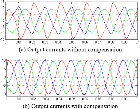
The waveforms of the output currents for 25 and 50 Hz are shown in Fig. 7 and Fig. 8, respectively. In Fig 7(a) and 8(a), the output currents of the uncompensated systems are given under the distorted input voltage conditions. As for the output currents of the compensated systems are illustrated in Fig. 7(b) and 7(b). In the uncompensated system, total harmonic distortions of the output current are respectively 16.62% and 9.61% for 25 and 50 Hz of the output frequency. In the compensated system, total harmonic distortions of the output current are respectively 3.45% and 2.07% for 25 and 50 Hz of the output frequency. As it is shown, if the input voltages of the MC are distorted or unbalanced, the low order harmonics occur on the output current and voltage of the MC. But, under the same conditions, the proposed PI controller based compensation method has effectively decreased these harmonics.
[image:4.595.70.270.110.246.2]The waveforms of the output voltages for 25 and 50 Hz are shown in Fig. 9 and Fig. 10, respectively. In Fig 9(a) and 10(a), the output voltages of the uncompensated systems are given under the distorted input voltage conditions. As for the output voltages of the compensated systems are illustrated in Fig. 9(b) and 10(b). The black pulsing diagram is the output line voltage and the green line is average of the output line voltage in figures. As it is understood from the average value of the output line voltage, the proposed compensation technique has satisfactorily eliminated the harmonics of the output voltage, too
[image:4.595.313.541.173.247.2]Fig. 5. Input voltages which have 20% third and 10% fifth harmonics
Fig. 6. Variation of the voltage gain
(a) Output currents without compensation
[image:4.595.311.539.281.461.2](b) Output currents with compensation Fig. 7. Three-phase output currents for MC the under
distorted input voltage conditions (fo = 25 Hz)
(a) Output currents without compensation
(b) Output currents with compensation Fig. 8. Three-phase output currents for MC the under
[image:4.595.312.540.517.695.2](a) Output currents without compensation
[image:5.595.54.285.48.225.2](b) Output currents with compensation
Fig 9. Output line voltages for the MC the under distorted input voltage conditions (fo = 25 Hz)
(a) Output currents without compensation
(b) Output currents with compensation
Fig 10. Output line voltages for the MC the under distorted input voltage conditions (fo = 50 Hz)
VI. CONCLUSIONS
A PI controller based compensation technique is proposed to improve the output performance of the MC. The proposed method has satisfactorily reduced harmonics in the output currents and voltages under the distorted input voltage conditions. In addition to, this method allows the over-current protection and the control of the load current. Under undesirable effects of the input supply voltage, the proposed compensation technique is an effective method to reduce harmonics of the output current and voltage. Validity of this method is verified by the presented simulation results.
REFERENCES
[1] M. Venturini, A New Sine Wave in Sine Wave out, Conversion Technique Which Eliminates Reactive Elements, Proceedings of Powercon 7, pp. E3/1-E3/15, 1980.
[2] A. Alesina, M. Venturini, “Analysis and Design of
Optimum-Amplitude Nine Switch Direct AC-AC Converters”, IEEE Trans. Power Electron., vol. 4, no.1, pp. 101-112, Jan. 1989. [3] P.W. Wheeler, J. Rodriguez, J.C. Clare, et al., “Matrix Converters: a
Technology Review”, IEEE Trans. Ind. Electron., Vol. 49, no.2, pp.276-288, April 2002.
[4] H. Karaca, R. Akkaya, “A Matrix Converter Controlled with the Optimum Amplitude-Direct Transfer Function Approach”, 6th
International Conference on Electrical Engineering ICEENG 2008, May 2008.
[5] D. Casadei, G. Serra and A. Tani, “Reduction of the Input Current Harmonic Content in Matrix Converters under Input /Output Unbalance” IEEE Trans. Ind. Electron., vol. 45, no. 3, pp. 401-409, June 1998.
[6] P. Nielsen, F. Blaabjerg, J. K. Pedersen, “Space Vector Modulated Matrix Converter with Minimized Number of Switchings and a Feedforward Compensation of Input Voltage Unbalance”, IEEE-PEDES’96, vol. 2, pp. 833-839, 1996.
[7] P. Nielsen, D. Casadei, G. Serra, A. Tani, “Evaluation of the Input Current Quality by Three Modulation Strategies for SVM Controlled Matrix Converters with Input Voltage Unbalance”, IEEE-PEDES’96, vol. 2, pp. 794-800, 1996.
[8] K. Sun, D. Zhou, L. Huang, K. Matsuse, “Compensation Control of Matrix Converter Fed Induction Motor Drive under Abnormal Input Voltage Conditions”, IEEE-IAS’04, pp. 623-630, 2004.
[9] M. E. O. Filho, E. R. Filho, K. E. B. Quindere, J. R. Gazoli, “A Simple Current Control for Matrix Converter”, IEEE-International Symposium on Industrial Electronics, pp. 2090-2094, 2006.
[10] S. Sünter, H. Altun, J. Clare, “A Control Technique for Compensating the Effects of Input Voltage Variations on Matrix Converter Modulation Algorithms”, Taylor&Francis-Electric Power Components and Systems, vol. 30, pp. 807-822, 2002.
[11] H. Karaca, R. Akkaya, H. Doğan, “A Novel Compensation Method Based on Fuzzy Logic Control for Matrix Converter under Distorted Input Voltage Conditions”, IEEE-International Conference on Electrical Machines, September 2008.
[12] S. Campbell, H. A. Toliyat, “DSP-Based Electromechanical Motion Control”, CRC Press, pp. 307-325, 2004.
[image:5.595.55.283.278.453.2]